Introduction to MSP430


Introduction to MSP430
- MSP430 is a microcontroller portfolio that offers different varieties of sixteen-bit Microcontrollers. These microcontrollers are integrated with ultra-low power and digital and analog peripherals devices for sensing and measurement applications.
- This module consists of five low-power modes that increase battery life in portable measurement applications.
- MSP430 has a feature of 16-bit registers, sixteen-bit RISC Cpu and constant generators which provides maximum code efficiency.
- The digitally controlled oscillator (DCO) of this module converts low power modes to active mode in less than 6µs.
- The MSP430x11x series is an ultra-low power signal microcontrollers that consist of a 16-bit timer and fourteen input and output pinouts.
- MSP microcontrollers give ideas and enable designers to produce such high-performance applications, which support the industry's lowest stand-by power, analog and digital devices suitable for sensing and measurement applications, and also support 20+ wired and wireless connectivity applications.
- The main applications that it provides are sensor systems that receive analog signals and convert them into digital values, and after processing this data sends to host modules. Another area of application is RF front-end sensor.

Pinout of MSP430
These are the main pinouts of MSP430 which are described below.| Pin# | Type | Parameters |
| Pin#13 | P1.0/TACLK | It is general-purpose digital I/O pin / Timer_A, clock signal TACLK input. |
| Pin#14 | P1.1/TA0 | It is general-purpose digital I/O pin/Timer_A, Capture: CCI0A input, Compare: Out0 output. |
| Pin#15 | P1.2/TA1 | It is general-purpose digital I/O pin/Timer_A, Capture: CCI1A input, Compare: Out1 output. |
| Pin#16 | P1.3/TA2 | It is general-purpose digital I/O pin/Timer_A, Capture: CCI2A input, Compare: Out2 output. |
| Pin#17 | P1.4/SMCLK/TCK | It is general-purpose digital I/O pin/SMCLK signal output/Test clock, an input terminal for device programming and test. |
| Pin#18 | P1.5/TA0/TMS | It is general-purpose digital I/O pin/Timer_A, Compare: Out0 output/test mode select, an input terminal for device programming and test. |
| Pin#19 | P1.6/TA1/TDI | It is general-purpose digital I/O pin/Timer_A, Compare: Out1 output/test data input terminal. |
| Pin#20 | P1.7/TA2/TDO/TDI | It is general-purpose digital I/O pin/Timer_A, Compare: Out2 output/test data output terminal or data input during programming. |
| Pin#8 | P2.0/ACLK | It is general-purpose digital I/O pin/ACLK output. |
| Pin#9 | P2.1/INCLK | It is general-purpose digital I/O pin/Timer_A, a clock signal at INCLK. |
| Pin#10 | P2.2/TA0 | It is general-purpose digital I/O pin/Timer_A, Capture: CCI0B input, Compare: Out0 output. |
| Pin#11 | P2.3/TA1 | It is general-purpose digital I/O pin/Timer_A, Capture: CCI1B input, Compare: Out1 output. |
| Pin#12 | P2.4/TA2 | It is general-purpose digital I/O pin/Timer_A, Compare Out2 output. |
| Pin#3 | P2.5/ROSC | It is general-purpose digital I/O pin/Input for an external resistor that defines the DCO nominal frequency. |
| Pin#7 | RST/NMI | It is Reset or nonmaskable interrupt input. |
| Pin#1 | TEST/VPP | It is selected test mode for JTAG pins on Port1/programming voltage input during EPROM programming. |
| Pin#2 | VCC | It is a Supply voltage. |
| Pin#4 | VSS | It is Ground reference. |
| Pin#6 | XIN | It is an Input terminal of the crystal oscillator. |
| Pin#5 | XOUT/TCLK | The output terminal of a crystal oscillator or test clock input. |

Features of MSP430
- These are the main features of MCP430, Lets's discuss them with detailed.
- It is available in a 20 pin plastic small outline widebody package.
- Its operating voltage range is 2.5v to 5.5 v.
- Its active mode is 330 µA at 1 MHz, 3 V.
- Its stands by mode are 1.5 µA.
- It's off mode (Ram Retention) is 0.1 µA.
- This module is available in 16-bit architecture, 200ns instruction cycle time.
- This module consists of various internal resistors, single external resistor,32 kHz crystal, high frequency, resonator and external clock source.
- It has a 16-bit timer with a three capture/compare registers.
- In this module, programme protection is done by a security fuse.
- It has serial onboard programming.
- This module has 16 kb flash, 512 B RAM, 8ch 10-bit ADC, two 16-bit timer
MSP340 Interfacing with RFID
- In the next coming lines, we will discuss MSP430 interfacing with RFID, first of all, we discuss components required for this circuit.
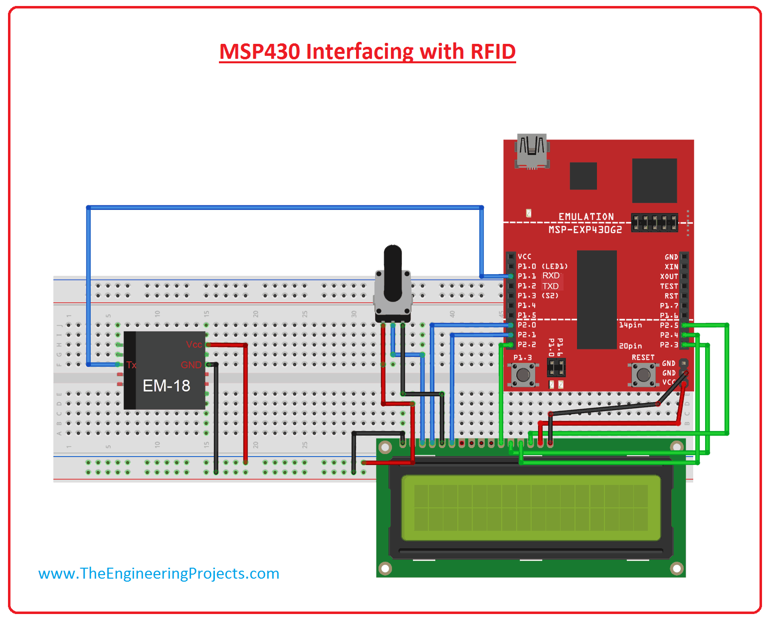
- Circuit Components
- MSP430 Launchpad.
- EM-18 (RFID reader module).
- 16*2 LCD.
- Potentiometer.
- Breadboard.
- Jumper wires.
- In this circuit diagram, we are going to use UART hardware of MSP430, So you should put RXD and TXD jumpers on HM UART mode. After this connect the Tx of EM-18 to RXD (P1.1) of MSP430.
- In this project, we are going to use serial communication of data transfer. RFID also has another mode than serial mode but we are using RS232 communication mode. The RS232 pin of RFID the module connects with RXD pin of MSP430.
- To connect the RFID reader with MSP430 we have to enable the serial communication in MSP430.
- We can initialize serial protocol in MSP430 by using a simple command Serial.begin(9600), where 9600 is the baud rate.
- Now in order to read the incoming Serial data, we need to use value=Serial.read().
- We can see in the given diagram that for communication by RFID use BAUD rate of 9600 bits per seconds. For MSP430 to create baud rate equal to the RFID baud rate to start communication, we use the command of "Serial.begin(9600);". 9600 is a baud rate which can change.
-
After setting of baud rate, MSP430 is ready to receive data. This data can be received by command “data = Serial.read();”. By this way, serial data is taken in 'data ' named Integer.
-
When we take a card near the reader, the reader reads data and forward it to MSP430, MSP430 after getting data show on LCD. So we will have an ID of a card on LCD.


Applications of MSP430
- These are some applications of MSP430.
- It is used for Factory Control & Automation Applications
- It is used in Building & Home Automation Applications.
- It is used in Grid Infrastructure & Metering Applications.
- It is used in Portable Test & Measurement Equipment.
- It is used in Health, Medical & Fitness Applications
- It also used in Consumer Electronics.
×
![]()