Introduction to BD139


Introduction to BD139
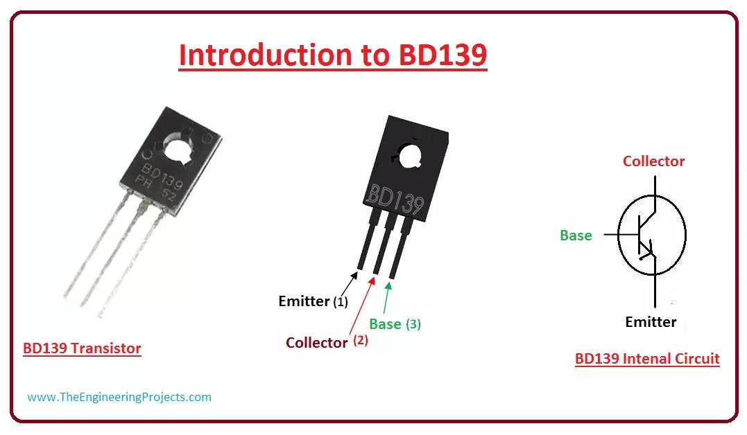
- BD139 is a Bipolar NPN transistor, mounted in the SOT-32 plastic package and is designed for audio amplifier and driver utilizing complementary circuits.
- Gain Value of BD139 ranges from 40 to 160. (Gain Value of any transistor helps in determining its amplification capacity)
- The maximum value of current, which can pass through collector pin, is 1.5A, so if you are working on this transistor then make sure that your load must be less than 1.5A.
- In order to operate this transistor in forward biased state, we have to apply current at its base and this base current must be greater than 1/10th of its collector current. Moreover, make sure to apply 5V at its base-emitter pin.
- Once it's operating in forward biased state, we can draw a maximum of 1.5A current between its Collector & Emitter. If maximum current i.e. 1.5A is flowing through a transistor then we can say it's in Saturation Region.
- Normally, we can apply a maximum of 80V across Collector & Emitter.
- When we remove base current transistor becomes fully off, this situation is called the cut-off region.
- One best point about it is that it comes in a plastic package, which is that most medium power transistor available only in the metal package. This reduces its cost and since this package is not conductive it will not be affected by other circuits. Due to this feature, it is mostly used in amplifier applications.
- So if you are searching for medium power NPN transistor in a plastic package than this will be the best choice for you.
- BD139 was originally manufactured by Phillips rated at 160 MHZ for specific audio applications, with a passage of time it was cloned by other manufacturers like Samsung, ST, etc.
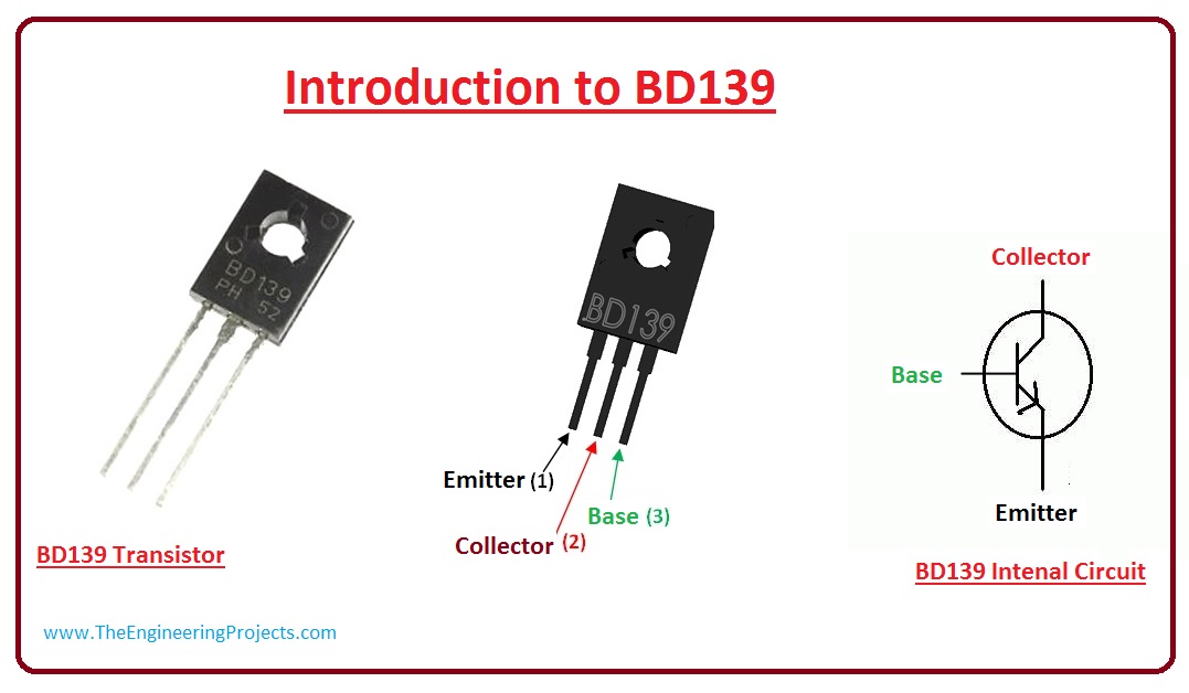
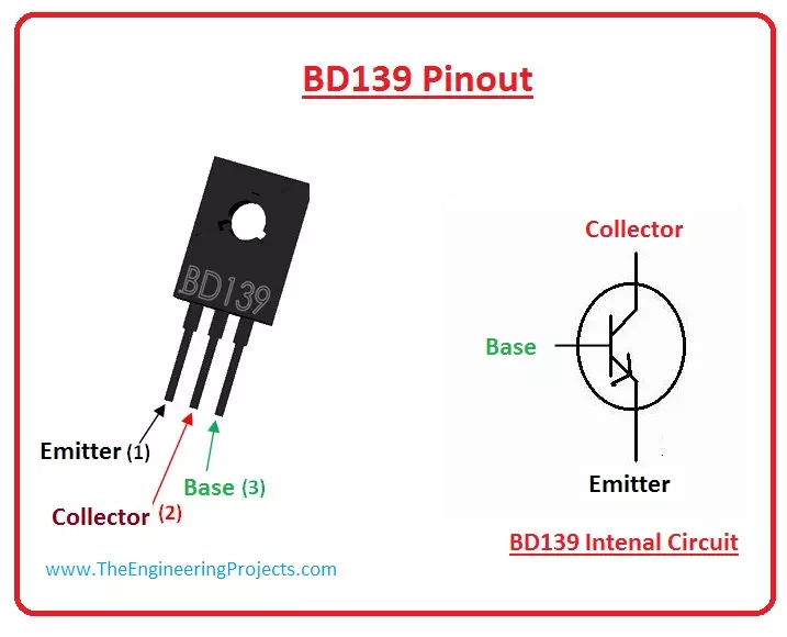
BD139 Pinout
- There are three main pinouts of BD129, which are described below with a detailed description.
| Pin# | Type | Parameters |
| Pin#1 | Emitter | An emitter is used for current Drains out, normally it is connected to ground. |
| Pin#2 | Collector | Current flows in through collector, normally it is connected to load. |
| Pin#3 | Base | Base controls the biasing of the transistor, it is used to turn ON or OFF the transistor. |
- For further information let's see BD139 pinout diagram.
Features of BD139
- These are the main features of BD139.
- It is Available in To-225 package.
- It is a plastic casing NPN transistor.
- Its continuous collector current (IC) is 1.5A.
- Its Collector-Emitter voltage is (VCE) is 80V.
- Its Collector-Base voltage. 80V
- Emitter-Base breakdown voltage (VBE) is 5V.
- Its DC current gain (hfe) is 40 to 160
- Emitter-Base Breakdown Voltage (VBE) is 5V
- Its collector dissipation factor is 12.5w.
- Its operating and storage junction temperature range is -55 to +150°C
- It is also available in PB-Free packages.
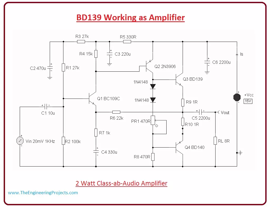
BD129 Working as Amplifier
- Now we discuss how we can use BD139 as an amplifier in or industrial and class projects.
- In a given circuit diagram, there is a 2-watt class-AB audio power amplifier which provides low harmonic distortion and wide frequency response.
- It has the capability of driving an 8O loudspeaker with an output power of 5 watts. In this circuit supply voltage is between 12V and 18V.
- In this 470O circuit, potentiometer controls the quiescent passes through BD139 and BD140 complementary transistors.
- Changes in values of this resistor is a trade-off between low distortion and low current across the output transistors Q3 and Q4.
- As this amplifier is DC biased, emitters of BD139 and BD1340 are at about half power supply voltage to allow for a maximum output swing. In this circuit, additional R9 and R10 resistor provide temperature stabilization.
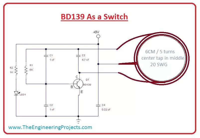
BD139 working as a Switch
- In given diagram circuit is designed to produce high magnetic flux. Center tapped coil is maid by 20 SWG Enameled copper wire 6 cm diameter and five turns with a center tap in middle.
- BD139 is acting a switch and oscillates high-frequency signal with the help of R1, C1, and C2 resonator.
- In this circuit, LED1 indicates the presence of bias to this circuit.
Applications of BD139
- These are some applications of BD139.
- It is used as RF Amplifiers.
- It is used in switching circuits
- It is used in amplification circuits
- It is used in audio amplifiers
- It is also used in Load driver circuits.
×
![]()