


Introduction to TIP31


Introduction to TIP31
- The TIP31 is a typical NPN transistor which is frequently cast-off for intermediate power submissions.
- It contains three (3) contrarily doped semiconductor parts, the collector area, the base section, and the emitter.
- These three parts are p-type, n category, and p category, correspondingly. Every of these part is linked to a point and suitably categorized.
- During a Connection of transistor components, it desires to do it sensibly since an improper linking can the origin of an instant and enduring harm to the transistor.
- There are four (4) conditions of processes for this sort of transistor forward-energetic, reverse- energetic, cut-off, and saturated region.
- Every assists a firm purpose and do a job which can be very valuable in numerous diverse circumstances.
- This can as well be used for intensification of the auditory signals.
- It is very adaptable and can be applied effortlessly into our different projects.
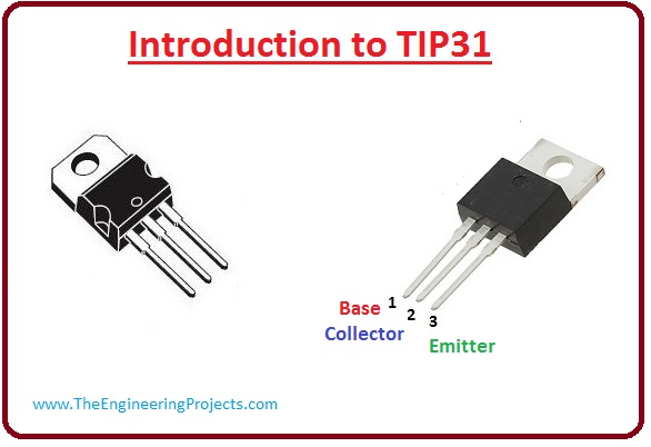
TIP31 Pinout
- These are the main pinouts of TIP31.
| Pin# | Type | Parameters |
| Pin#1 | Emitter | Current initiates out by the emitter, it is usually connected to ground. |
| Pin#2 | Base | It accomplishes the biasing of the transistor and mechanisms to turn ON or OFF the transistor. |
| Pin#3 | Collector | Current travels in over collector, normally it is connected to load. |

Features of TIP31
- These are the main features of TIP31.
- This definite transistor can be used in numerous circumstances and typically acts in an alike method even if this portion is acquired from a dissimilar builder.
- The permeation(saturation) voltage for the collector and emitter terminal is 1.2 volts whereas the base and emitter permeation(saturation) voltage are 1.8 volts.
- It does not necessitate a large power to start this transistor then the rate is also not small wherever an untrue initiation would happen.
- The gain of this transistor can vary from twenty (20) to twenty-five (25), which can be enormously valuable particularly when intensifying auditory signals.
- Its Maximum Working Connection Temperature is 150 centigrade.
- Its changeover (transition) frequency three (3) MegaHz.
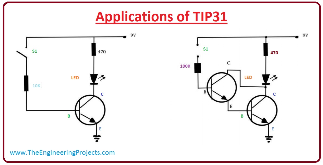
Applications of TIP31
- These are some important applications of TIP31.
-
- The submissions of this bipolar junction transistor originate two elementary thoughts.
- It used to produce a switching circuitry or an amplifier circuitry.
- Theist circuit in given diagram demonstrations the appropriate fitting of this expedient to work as a switching device which will on a LED.
- In given circuit when the (S1) switch is on, current initiates the movement towards the base of the transistor triggering it to start.
- The connection VCE currently is capable to permit current movement which triggered the (Light Emitting Diode) LED.
- In the given diagram, the 2nd circuit displays how two transistors can be shaped to procedure a pretty powerful amplifier circuitry.
- When the exposed (open) circuitry at the switch (S1) is substituted with a short circuit, current initiates to movement to the Ist transistor.
- This sources intensification in the current and also on the 2nd transistor. It happens since the emitter of the ist transistor is unswervingly linked with the base of the 2nd.
- The 2nd transistor will now dowse and source the LED to trigger. The resultant yield of the 2nd emitter has been intensified two times.

×
![]()


