Hi readers! I hope you are doing well and exploring new things daily. Do you know about the crankshaft position sensor? Today we will discuss the crankshaft position sensor with a detailed overview of its working, functioning, structure, and types. The crankshaft position sensor is an important part of internal combustion engines in modern automobiles. It finds the crankshaft’s position and rotational speed (RPM) and transmits this information to the Engine Control Unit (ECU). For optimum performance and fuel efficiency in making a vehicle operate smoothly, the crankshaft position checks the ignition timing, fuel injection, and valve timing. In the case of a non-functional CKP sensor, the engine may behave in a manner that does not start at all, misfires or works inefficiently.
CKP sensors work by picking the movement of a trigger wheel (tone ring) mounted to the crankshaft, which rotates during cranking, and with the help of magnetic sensing of the teeth or slots of the trigger wheel passing past the sensor, leads to an output generated from the device. This output is then communicated to the ECU as an input to compute the engine's speed and piston position for optimizing fuel injection and ignition timing. This sensor's accuracy is very critical for the smooth performance of the engine and vehicle reliability at large.
Crankshaft position sensors have three types. Magnetic Inductive Sensors are those which induce electromagnetism to generate an AC signal. However, these are always reliable sensors but not very effective at low vehicle speeds. Hall Effect Sensors produce a digital pulse signal of the crankshaft position precisely. Optical Sensors monitor the crankshaft movement using an LED and photodetector but are more prone to dirt and domestic debris. Each sensor has its advantages, but they all serve the same basic purpose of measuring crankshaft displacement.
A malfunctioning CKP Sensor might have caused deep-rooted vehicle problems such as troublesome engine starting, engine misfires, slow acceleration, and even an abrupt engine stalling. Due to the importance of synchronization in the engine functioning, it would cause poor performance with high fuel consumption and a possibility of damage to the engine. The on-time and authentic replacement, and maintenance of an unfit CKP sensor, are essential for the reliability and efficiency of the car.
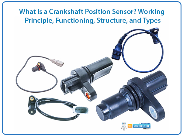
Here you find a deep understanding of the crankshaft position sensor with a detailed overview of its working principle, functioning, structure, and types. Let’s dive.
Types of Crankshaft Position Sensors:
Crankshaft position sensors are categorized according to the technology they employ to detect crankshaft movement. There are the fundamental types that are mentioned below:
1. Magnetic Inductive Sensor (Variable Reluctance Sensor):
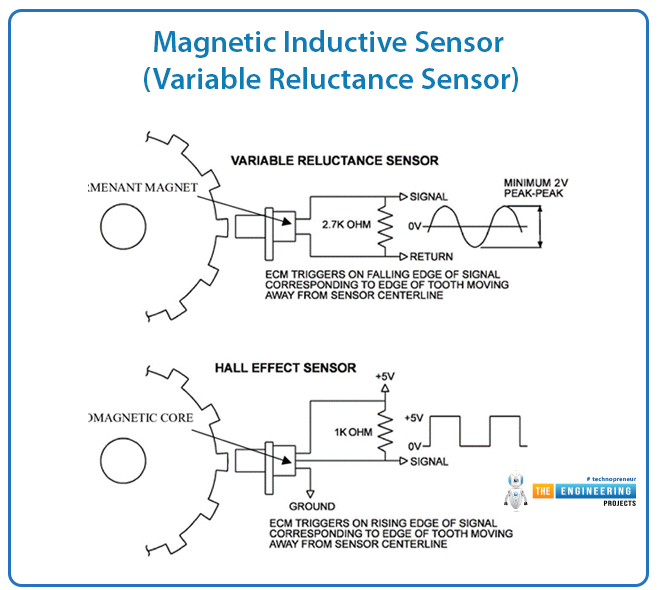
The Magnetic Inductive Sensor is based on electromagnetic induction. It consists of a magnet wrapped with a coil of wire and hence generates a magnetic field. The teeth approaching the sensor cut the magnetic field and generate a voltage in the coil whenever the trigger wheel (tone wheel) rotates.
This generates a voltage that generates an alternating current (AC) signal, whose amplitude and frequency are changing with crankshaft speed. The ECU demodulates the AC signal to determine engine RPM and crankshaft position.
Advantages:
Very simple and very robust.
Robust when used at high speed.
No external power supply is required.
Disadvantages:
The low-speed signal is weak and needs amplification.
Generate an analog signal, which may need to be digital before processing.
Common Applications:
Used on older vehicles and heavy-duty engines due to their long life.
2. Hall Effect Sensor:
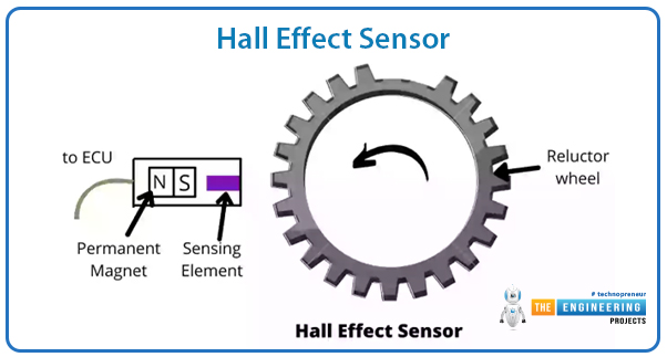
The Hall Effect Sensor is made on the principle of a semiconductor chip and a permanent magnet that indicates the crankshaft rotation. As the teeth of the trigger wheel sweep past, they oscillate the magnetic field, which is picked up by the semiconductor chip. The oscillation is then converted into a digital pulse signal with convenient processing by the ECU. The Hall Effect sensor produces a square wave output signal that is independent of the speed in contrast to magnetic sensors. This gives better readings and better low-speed performance.
Advantages:
More precise than magnetic sensors, especially at low speeds.
Provides a clean, noise-free digital output.
Can be used with sophisticated electronic control systems.
Disadvantages:
Requires an external power source to operate.
A bit more complex than magnetic sensors.
Common Applications:
Employed in contemporary vehicles with advanced ignition and fuel injection systems.
3. Optical Sensor:
The Optical Sensor is an apparatus that uses the LED and photodetector for crankshaft rotation sensing. It is mounted with the slotted disc on the crankshaft to block the light beam at regular intervals when the crankshaft rotates and unblock the same light when the crankshaft rotates. These are converted into electric pulses with the assistance of the photodetector and will be read by the ECU as crankshaft position and rate.
Optical sensors are very accurate and pick up even the smallest movements. They are very sensitive to contaminants such as dust, oil, and debris that interfere with the light beam, and therefore reduce performance.
Advantages:
High accuracy reading.
Ideal for high-performance engines that need proper control.
Disadvantages:
Sensitive to oil, dirt, and debris.
Less robust in tough engine environments.
Common Applications:
Utilized in racing cars and high-performance cars that require accurate ignition timing.
Working Principles of Crankshaft Position Sensors:
The Crankshaft Position Sensors (CKP Sensors) are important in an internal combustion engine. It relays to the Engine Control Unit (ECU) immediate data of the position and crankshaft rotating speed (RPM). This data is very important to control ignition timing, fuel injection, and valve operation to ensure maximum smoothness and economy of the engine.
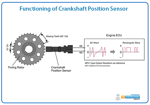
Being an inductive sensor, the CKP sensor is usually mounted near a trigger wheel (tone ring) mounted on either the crankshaft and/or flywheel. The trigger wheel has teeth spaced at specific intervals upon which the crankshaft rotates while the teeth pass in front of the sensor. The sensor detects the teeth and produces electrical signals about the movement, and thus these signals can be interpreted by the ECU.
Another way the signals can be generated is dependent on the kind of sensor being used. These methods are as follows:
Magnetic Inductive Sensor (Variable Reluctance Sensor):
This CKP sensor uses electromagnetic induction to generate an alternating current (AC) signal.
In the sensor, a magnetic coil produces a static magnetic field. Teeth from the trigger wheel interrupting this field generate a voltage signal.
The amplitude and frequency of this AC signal are determined by the speed of the engine, that is, the faster the crankshaft turns, the higher will be the AC signal strength.
They are rather simple, tough, and reliable at higher speeds; however, their signal strength tends to drop at lower speeds, which often causes the need for extra amplification.
Hall Effect Sensor:
Like the crankshaft position sensor, Hall Effect sensors are nothing more than a semiconductor chip and a permanent magnet.
With the teeth on the trigger wheel passing close to the sensor, the changes in the magnetic field produced are detected by the semiconductor and converted into a digital ON/OFF pulse signal.
The sensor produces a rectangular wave output that is easy to process for the ECU.
Hall Effect sensors are more accurate for low engine speed than magnetic ones and output a constant signal independent of RPM.
Optical Sensor:
The optical sensor sensed the crankshaft motion using a light-emitting diode (LED) and a photodetector.
The crankshaft incorporates a slotted disc. With a rotation of the disc, it interrupts the LED light, thus generating pulses in proportion to the crankshaft position.
Accurate optical sensors are good for performance applications. Optical sensors are, however, sensitive to oil, dirt, and debris and prone to loss of accuracy.
The signal produced by the CKP sensor is received by the ECU, which gives the data a format in which it can recognize the crankshaft's position and speed. This data is thus employed for controlling fuel injection and ignition timing to give proper combustion and normal engine operation.
Functioning of Crankshaft Position Sensor:
Several important jobs have been executed by crankshaft position sensors in making the engine reliable and efficient.
Determining the Position of Crankshaft:
This is one of its key jobs; conjuring the exact position of the crankshaft. The information will be sent to the ECU as the pistons inside the cylinders are moved. The timing of fuel injection as well as ignition is ensured to be correct based on this data. In as much as combustion has improved, the power output of the engine has been improved. Thus, the knocking of the engine has been reduced, which further improves the efficiency of fuel and contributes to the entire increase in power production.
Measuring Engine Revolutions:
In essence, the sensor calculates revolutions of the engine as RPM by the amount of times the crankshaft rotates over a minute. This can be achieved simply by measuring how many trigger wheel teeth pass the sensor over the period. Real-time information is passed to the ECU for varying ignition timing and fuel usage depending on changes in engine speed. More rotations per minute mean more acceleration, which means that the ECU will give more fuel; less rev means less acceleration, which requires adjustment for efficiency and emissions.
Camshaft Position Sensor Synchronization:
A few other new cars use that technology in conjunction with the crankshaft position sensor and camshaft position sensor. These sensors are: camshaft position sensor for monitoring valve movements and crankshaft position sensor for monitoring piston position. By synchronizing these two sensors, the ECU would be able to modify the programming of its variable valve timing (VVT) also with the sequential fuel injection. So it promises better fuel economy to the user, increased power delivery, and reduced harmful gases polluting the environment.
Avoiding Misfires and Stalling:
The crankshaft position sensor is the main device that postpones the stalling and misfiring of the engine. In case of any default or wrong signals sent from the sensor, the incorrect fuel injection or firing of spark plugs will occur, resulting in poor acceleration, rough idling, and at times would lead to engine hesitation. In a few cases, it can also make the engine stop running, which can lead to safety hazards. Misfiring can be observed due to unburned fuel entering into the exhaust system, ruining the catalytic converter, and adding to emissions.
Helping the Engine Start:
Most vehicles now use crankshaft position sensor information to determine the crankshaft starting position to start the engine. If the sensor itself is faulty, not functioning, or any other problem, the ECU would not be able to ascertain the position of the crankshaft. For safety against potential damage to the engine, the ECU is coded to cut fuel injection and ignition in some circumstances. The crankshaft position sensor might be faulty if the vehicle does not start or does not crank at all.
Structure of Crankshaft Position Sensor:
The crankshaft position sensor has parts designed to perform reliably under extreme engine conditions of high heat, vibration, and exposure to oil and dirt. These comprise various significant parts that allow for reliable data acquisition and transmission to the ECU.
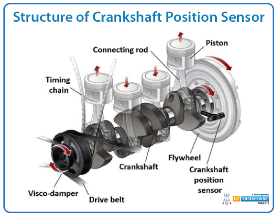
Housing:
The sensor housing comprises either metal or hard plastic to protect its interiors from heat, oil, and mechanical stress. The housing allows a sensor to be adapted to withstand future long exposure to conditions in the engine compartment that prove to be severe.
Sensing Element:
The sensing element in a crankshaft position sensor depends on its design:
The sensors of the magnet employ a coil along with a permanent magnet that is responsible for the generation of an alternating current (AC) signal whenever the trigger wheel rotates across the sensor.
Hall effect sensors utilize a semiconductor chip that monitors the change of a magnetic field, thus causing a digital pulse signal to be generated for the ECU.
Optical sensors use an LED and photodetector to sense the interruption of a light beam caused by the slotted trigger wheel.
Trigger Wheel (Tone Wheel / Pulse Wheel):
The trigger wheel known as the tone wheel or pulse wheel, is mounted on the flywheel or crankshaft. It is made with teeth placed uniformly, but some designs feature a missing tooth for the ECU to recognize cylinder 1 top dead center. The passing teeth are recognized and reported by each sensor to the ECU with calculations performed for engine timing.
Electrical Connector and Wiring Harness:
The sensor is linked to the ECU through an insulated wiring harness. The wires are grounded to prevent electromagnetic interference, ensuring proper and consistent signal transmission. A faulty wiring harness may lead to compromised sensor performance, causing improper readings and engine malfunction.
Conclusion:
The Crankshaft Position Sensor has become indispensable in modern systems of managing engine operations. It is responsible for the precision timing of ignition, fuel injection, and all other functions that involve engine synchronization. It has ways of determining the position and speed of the crankshaft by magnetic induction, using Hall effect, or optical sensing, and gives real-time data to the ECU for optimum engine performance.
The fault in the sensor may not start, can misfire, run roughly while idling, give poor acceleration, or the engine might fail. Because the CKP sensor is important for engine performance, it must be inspected and replaced in time to prevent future breakdowns. A well-functioning crankshaft position sensor is key to improving fuel use behavior and emission reduction while enhancing the driving experience, thus proving vital in the overall running of cars.


 Embedded Sensors
 xeohacker
 0 Comments


