Hello friends, I hope you are doing well. This is the eighteenth tutorial in our series on how to create a Proteus library. In the previous tutorial, How to Create a Proteus Simulation Model DLL in C++, we wrote TEPTRAFFIC.DLL, a model for our Traffic Light Module that honours its LOGIC property, and linked it to a new part, TRAFFICLIGHTVSMTEP. The model already draws the lamps. Today, it draws much more. Our topic is how to add a live control panel to a Proteus component.
A live control panel is a small instrument that belongs to the part itself: it sits next to the module on the schematic, shows what the model sees while the simulation runs, and has buttons that change the model's behaviour without stopping the run. Our panel shows the level of each input pin and the state of each lamp, counts how often a lamp switched on, flips LOGIC between High and Low with one click, and lights all lamps while a LAMP TEST button is held down. On the way, we met two surprises that cost us an evening, and we show both, because you will meet them too.
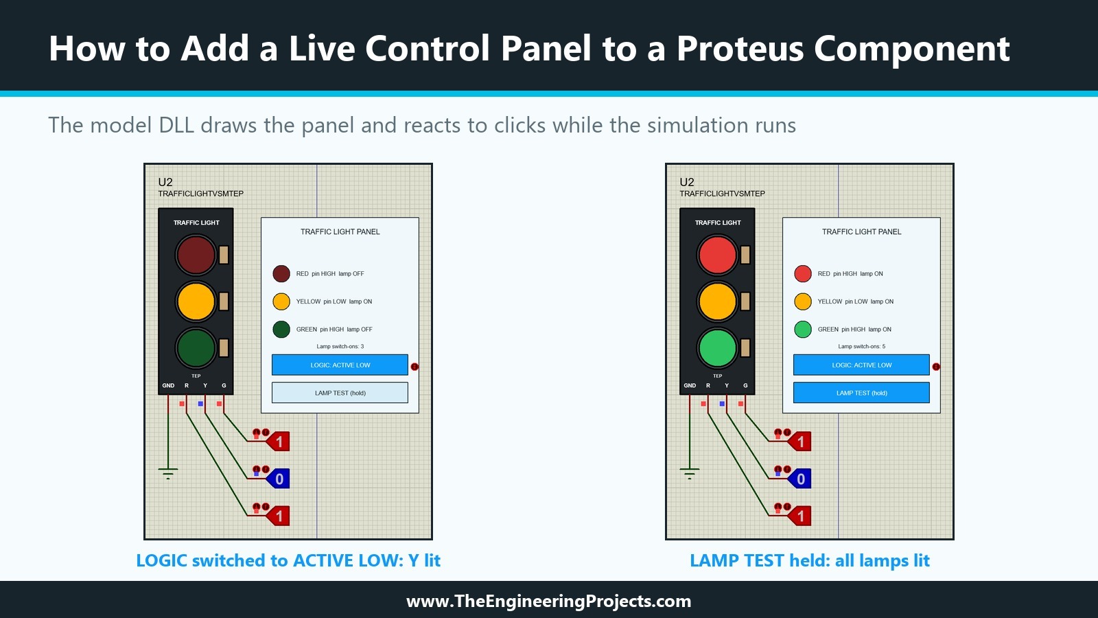
Everything shown here was done in Proteus 8.5 Professional and Visual Studio 2026 Community on our PC. The picture below shows the result during a simulation: on the left, the panel after one click on LOGIC, with the module now active low; on the right, the same panel while LAMP TEST is held down.
What Is a Live Control Panel in Proteus?
Many of Proteus's own parts have more than lamps and switches. The virtual instruments open windows of their own, and the models of our TEP libraries use both kinds of interface: the TEP Serial Monitor opens a popup window, and the model of the TEP RFID reader draws card buttons right next to the module on the sheet. In this tutorial, we build the second kind, because it needs nothing but the drawing services the model already uses.
Drawing Services of the Component
In the previous tutorial, our model used only two calls of the ICOMPONENT interface: setstate to choose the state symbols and drawstate to draw them. The same interface offers a complete set of vector drawing services: graphics and text styles, pen and brush colours, lines, boxes, circles, polygons and text. A model can call them in plot, when the part is drawn, and in animate, when new data arrives from the simulator. Whatever it draws becomes part of the picture of the placed component.
Clicks Arrive in actuate
The other half of a panel is input. IACTIVEMODEL has a function called actuate, which receives the position of the mouse in the part's own coordinates and flags that say which button is down. In the previous tutorial, our actuate simply returned FALSE. Today, it decides which panel button was hit.
Two Threads, One Object
There is one complication. The drawing side runs in the schematic editor and the simulator side in the simulator, and both call the same C++ object. A click in actuate cannot simply call into the simulator; it can only leave a note that the simulator side reads later. Our TEP models solve this with std::atomic variables, which both sides can read and write safely, and so does our panel.
How Our Panel Works
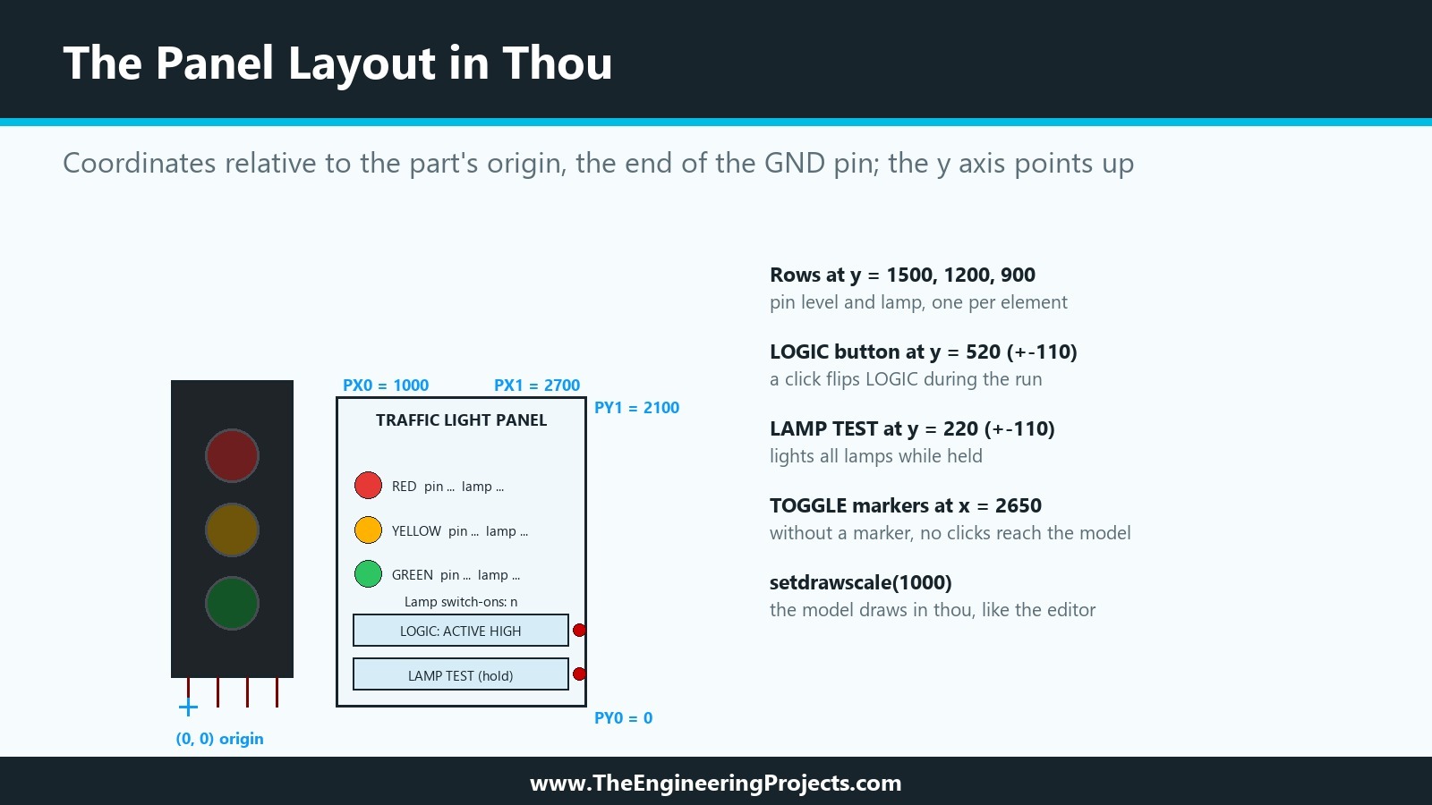
Before we look at the code, here is the plan of the panel, drawn to scale. All coordinates are in thou, relative to the part's origin, which is the end of the GND pin, with the y axis pointing up, as in the editor.
From the Simulator to the Panel
The panel needs more than the lamp pattern: the level of each pin, the LOGIC setting, the LAMP TEST state and the switch-on counter. indicate can pass a single integer to the drawing side, so the model packs all of it into one number. Bits 0 to 2 hold the lamps as before, bits 3 to 8 hold the three pin levels with two bits each (LOW, HIGH or open), bit 9 says active low, bit 10 says lamp test, and the bits from 11 up hold the counter. animate unpacks the number, sets the lamp states and draws the panel.
From the Panel to the Simulator
A click on LOGIC increases a click counter, and a press on LAMP TEST sets a flag. Both are atomic. The simulator side compares the counter with the last value it has seen, flips LOGIC for every new click and writes a line to the simulation log.
Why the Model Needs a Timer
In the previous tutorial, the simulator called simulate only when one of the pins changed. A click on the panel changes no pin, so nothing would ever look at it. The panel version therefore asks the simulator for a callback every 10 milliseconds of simulation time with setcallback, and the callback reads the panel and schedules the next one. The source of our TEP RFID model uses the same pattern for its card buttons.
How to Add a Live Control Panel to a Proteus Component: Step by Step
We added the panel in five steps: the model code, the build, the part, the markers and the test, with one detour for a click that arrived twice.
Step 1: Extend the Model
Here is the complete source of the panel version, TrafficLightPanel.cpp. It replaces TrafficLightModel.cpp from the previous tutorial and builds the same TEPTRAFFIC.DLL, so parts that already use the DLL get the panel without any change to their MODDLL property.
// TEP Traffic Light Module - Proteus VSM model DLL with a live control panel (TEPTRAFFIC.DLL v1.1)
// The Engineering Projects - www.TheEngineeringProjects.com
//
// Pins  : R, Y, G (digital inputs), GND (optional; the lamps stay dark unless it is LOW)
// LOGIC : 1 = a lamp lights when its pin is HIGH, 0 = when its pin is LOW
// PANEL : 1 = draw the control panel next to the module, 0 = no panel
// Panel : shows the pin levels and lamps, counts lamp switch-ons, flips LOGIC while the
//         simulation runs (LOGIC button) and lights all lamps while LAMP TEST is held down.

#include <cstddef>   // NULL, which vsm.hpp uses
#include <atomic>
#include "vsm.hpp"

namespace {
constexpr EVENTID EVT_POLL = 1;
constexpr double POLL_SECONDS = 0.01;   // the simulator looks at the panel every 10 ms

// Panel geometry in thou, relative to the origin of the part (the end of its GND pin).
constexpr int PX0 = 1000, PX1 = 2700, PY0 = 0, PY1 = 2100;
constexpr int ROW_Y[3] = {1500, 1200, 900};
constexpr int LOGIC_Y = 520, TEST_Y = 220, BUTTON_HALF = 110;

// The simulator side sends one integer to the drawing side:
// bits 0-2 lamps, bits 3-8 pin levels (2 bits per pin), bit 9 active-low, bit 10 lamp test,
// bits 11-26 number of lamp switch-ons since the start of the run.
int pack(int lamps, const int levels[3], bool activeLow, bool test, int switchOns) {
    return lamps | levels[0] << 3 | levels[1] << 5 | levels[2] << 7 | int(activeLow) << 9 | int(test) << 10 |
           (switchOns & 0xFFFF) << 11;
}
}

class TrafficLightModel : public IDSIMMODEL, public IACTIVEMODEL {
    // Drawing side (schematic editor)
    ICOMPONENT* component_ = nullptr;
    HGFXSTYLE gfx_ = nullptr;
    HTEXTSTYLE txt_ = nullptr;
    bool panel_ = true;
    int shown_ = 0;               // last packed value received from the simulator side

    // Written by the drawing side when the panel is clicked, read by the simulator side.
    std::atomic<int> logicClicks_{0};
    std::atomic<bool> lampTest_{false};
    bool mouseDown_ = false;      // a panel button is held; ignore further presses until release

    // Simulator side
    IINSTANCE* instance_ = nullptr;
    IDSIMCKT* circuit_ = nullptr;
    IDSIMPIN *red_ = nullptr, *yellow_ = nullptr, *green_ = nullptr, *gnd_ = nullptr;
    bool activeHigh_ = true, running_ = false;
    int seenClicks_ = 0, lamps_ = 0, switchOns_ = 0, packed_ = 0, reported_ = -1;
    int levels_[3] = {2, 2, 2};   // 0 = LOW, 1 = HIGH, 2 = open or undefined

    // Reads a Yes/No or High/Low property: 0, No, False and Low are off, anything else is on.
    static bool isOn(const char* text) {
        if (!text || !*text) return true;
        const char c = text[0];
        return !(c == '0' || c == 'N' || c == 'n' || c == 'F' || c == 'f' || c == 'L' || c == 'l');
    }
    static int level(IDSIMPIN* pin) {
        const STATE s = pin->istate();
        return ishigh(s) ? 1 : islow(s) ? 0 : 2;
    }

    // Simulator side: read the pins and the panel, then work out the lamps.
    void update(ABSTIME) {
        const int clicks = logicClicks_.load();
        if (clicks != seenClicks_) {
            if ((clicks - seenClicks_) % 2) activeHigh_ = !activeHigh_;
            seenClicks_ = clicks;
            instance_->log((CHAR*)"TEP Traffic Light: panel set LOGIC to active %s", activeHigh_ ? "HIGH" : "LOW");
        }
        IDSIMPIN* pins[3] = {red_, yellow_, green_};
        const bool grounded = !gnd_ || islow(gnd_->istate());
        const bool test = lampTest_.load();
        int lamps = 0;
        for (int i = 0; i < 3; ++i) {
            levels_[i] = level(pins[i]);
            const bool on = test || (grounded && levels_[i] == (activeHigh_ ? 1 : 0));
            if (on) lamps |= 1 << i;
        }
        for (int i = 0; i < 3; ++i)
            if ((lamps & ~lamps_) >> i & 1) ++switchOns_;
        lamps_ = lamps;
        packed_ = pack(lamps_, levels_, !activeHigh_, test, switchOns_);
    }

    // Drawing side: the panel.
    void button(int y, const char* text, bool active) {
        component_->selectgfxstyle(gfx_);
        component_->setpenwidth(6);
        component_->setpencolour(MAKECOLOUR(23, 36, 43));
        component_->setbrushcolour(active ? MAKECOLOUR(14, 154, 249) : MAKECOLOUR(214, 236, 246));
        component_->drawbox(PX0 + 120, y - BUTTON_HALF, PX1 - 120, y + BUTTON_HALF);
        component_->selecttextstyle(txt_);
        component_->settextcolour(active ? MAKECOLOUR(255, 255, 255) : MAKECOLOUR(23, 36, 43));
        component_->settextsize(80);
        component_->drawtext((PX0 + PX1) / 2, y, 0, TXJ_CENTRE | TXJ_MIDDLE, (CHAR*)text);
    }
    void drawPanel() {
        if (!panel_) return;
        static const char* names[3] = {"RED", "YELLOW", "GREEN"};
        static const char* levelText[3] = {"LOW", "HIGH", "OPEN"};
        static const COLOUR lampOn[3] = {MAKECOLOUR(230, 57, 53), MAKECOLOUR(255, 179, 0), MAKECOLOUR(46, 196, 98)};
        static const COLOUR lampOff[3] = {MAKECOLOUR(110, 30, 30), MAKECOLOUR(110, 85, 10), MAKECOLOUR(20, 85, 40)};
        const int lamps = shown_ & 7;
        const bool activeLow = shown_ >> 9 & 1, test = shown_ >> 10 & 1;
        component_->selectgfxstyle(gfx_);
        component_->setpenwidth(8);
        component_->setpencolour(MAKECOLOUR(23, 36, 43));
        component_->setbrushcolour(MAKECOLOUR(240, 248, 252));
        component_->drawbox(PX0, PY0, PX1, PY1);
        component_->selecttextstyle(txt_);
        component_->settextcolour(MAKECOLOUR(23, 36, 43));
        component_->settextsize(95);
        component_->drawtext((PX0 + PX1) / 2, PY1 - 150, 0, TXJ_CENTRE | TXJ_MIDDLE, (CHAR*)"TRAFFIC LIGHT PANEL");
        for (int i = 0; i < 3; ++i) {
            const bool on = lamps >> i & 1;
            component_->selectgfxstyle(gfx_);
            component_->setpenwidth(6);
            component_->setpencolour(MAKECOLOUR(23, 36, 43));
            component_->setbrushcolour(on ? lampOn[i] : lampOff[i]);
            component_->drawcircle(PX0 + 220, ROW_Y[i], 90);
            component_->selecttextstyle(txt_);
            component_->settextcolour(MAKECOLOUR(23, 36, 43));
            component_->settextsize(75);
            component_->drawtext(PX0 + 380, ROW_Y[i], 0, TXJ_LEFT | TXJ_MIDDLE, (CHAR*)"%s  pin %s  lamp %s", names[i],
                                 levelText[shown_ >> (3 + 2 * i) & 3], on ? "ON" : "OFF");
        }
        component_->settextsize(70);
        component_->drawtext((PX0 + PX1) / 2, 720, 0, TXJ_CENTRE | TXJ_MIDDLE, (CHAR*)"Lamp switch-ons: %d", shown_ >> 11 & 0xFFFF);
        button(LOGIC_Y, activeLow ? "LOGIC: ACTIVE LOW" : "LOGIC: ACTIVE HIGH", activeLow);
        button(TEST_Y, "LAMP TEST (hold)", test);
    }

public:
    // IACTIVEMODEL: drawing the part
    VOID initialize(ICOMPONENT* component) override {
        component_ = component;
        component_->setdrawscale(1000);
        gfx_ = component_->creategfxstyle();
        txt_ = component_->createtextstyle();
        component_->settextfont((CHAR*)"Arial");
        panel_ = isOn(component_->getprop((CHAR*)"PANEL"));
        const bool activeLow = !isOn(component_->getprop((CHAR*)"LOGIC"));
        const int levels[3] = {2, 2, 2};
        shown_ = pack(0, levels, activeLow, false, 0);
    }
    ISPICEMODEL* getspicemodel(CHAR*) override { return nullptr; }
    IDSIMMODEL* getdsimmodel(CHAR*) override { return this; }
    VOID plot(ACTIVESTATE state) override {
        component_->drawstate(state);
        drawPanel();
    }
    VOID animate(INT, ACTIVEDATA* data) override {
        if (!data || data->type != ADT_INTEGER) return;
        shown_ = data->intval;
        component_->setstate(shown_ & 7);
        drawPanel();
    }
    BOOL actuate(WORD, INT x, INT y, DWORD flags) override {
        if (!panel_) return FALSE;
        if (flags & 0x80000000UL) return TRUE;     // a repeat of the event we already handled
        if (!(flags & ACF_LEFT)) {                  // mouse button released
            mouseDown_ = false;
            const bool wasTesting = lampTest_.exchange(false);
            return wasTesting ? TRUE : FALSE;
        }
        if (mouseDown_) return TRUE;                // still the same press
        if (x < PX0 + 120 || x > PX1) return FALSE;
        if (y >= LOGIC_Y - BUTTON_HALF && y <= LOGIC_Y + BUTTON_HALF) { mouseDown_ = true; ++logicClicks_; return TRUE; }
        if (y >= TEST_Y - BUTTON_HALF && y <= TEST_Y + BUTTON_HALF) { mouseDown_ = true; lampTest_ = true; return TRUE; }
        return FALSE;
    }

    // IDSIMMODEL: simulating the part
    INT isdigital(CHAR*) override { return TRUE; }
    VOID setup(IINSTANCE* instance, IDSIMCKT* circuit) override {
        instance_ = instance;
        circuit_ = circuit;
        red_ = instance->getdsimpin((CHAR*)"R", TRUE);
        yellow_ = instance->getdsimpin((CHAR*)"Y", TRUE);
        green_ = instance->getdsimpin((CHAR*)"G", TRUE);
        gnd_ = instance->getdsimpin((CHAR*)"GND", FALSE);
        activeHigh_ = isOn(instance->getstrval((CHAR*)"LOGIC", (CHAR*)"1"));
        seenClicks_ = logicClicks_.load();
        lamps_ = switchOns_ = 0;
        reported_ = -1;
        running_ = true;
        circuit_->setcallback(dsimtime(POLL_SECONDS), this, EVT_POLL);
        instance->log((CHAR*)"TEP Traffic Light: model started, lamps light when a pin is %s",
                      activeHigh_ ? "HIGH" : "LOW");
    }
    VOID runctrl(RUNMODES mode) override { if (mode == RM_STOP) running_ = false; }
    VOID actuate(REALTIME, ACTIVESTATE) override {}
    BOOL indicate(REALTIME, ACTIVEDATA* data) override {
        if (packed_ == reported_) return FALSE;
        reported_ = packed_;
        data->type = ADT_INTEGER;
        data->intval = packed_;
        return TRUE;
    }
    VOID simulate(ABSTIME time, DSIMMODES mode) override { if (mode != DSIMEND) update(time); }
    VOID callback(ABSTIME time, EVENTID) override {
        if (!running_) return;
        update(time);
        circuit_->setcallback(time + dsimtime(POLL_SECONDS), this, EVT_POLL);
    }
};

// Proteus calls these four functions to create and delete the model objects.
extern "C" __declspec(dllexport) IACTIVEMODEL* createactivemodel(CHAR*, ILICENCESERVER* server) {
    return server && server->authorize(0) ? new TrafficLightModel : nullptr;
}
extern "C" __declspec(dllexport) VOID deleteactivemodel(IACTIVEMODEL* model) {
    delete static_cast<TrafficLightModel*>(model);
}
extern "C" __declspec(dllexport) IDSIMMODEL* createdsimmodel(CHAR*, ILICENCESERVER* server) {
    return server && server->authorize(0) ? new TrafficLightModel : nullptr;
}
extern "C" __declspec(dllexport) VOID deletedsimmodel(IDSIMMODEL* model) {
    delete static_cast<TrafficLightModel*>(model);
}
Drawing the Panel
initialize sets the draw scale to 1000 units per inch, so the model draws in thou like the editor, creates one graphics style and one text style, and reads the PANEL and LOGIC properties from the component, because the panel must look right before the first run. drawPanel draws the frame, the title, one row per lamp with a circle in the lamp's on or off colour and a line of text, the counter and two buttons. A button that is active, LOGIC set to Low or LAMP TEST held, is drawn in our blue with white text.
Handling the Mouse
actuate first checks whether the left button is down. If it is not, the button was released, and LAMP TEST ends. If it is, the model checks whether the mouse is inside one of the two buttons and acts on it. The return value tells Proteus whether the model used the click.
Reading Properties Again
isOn reads both of our property types: LOGIC, which Proteus stores as 1 or 0, and the new PANEL property, which is a Yes/No property. Anything that starts with 0, N, F or L counts as off.
Step 2: Build and Install the DLL
We built the DLL exactly as in the previous tutorial, with the 32-bit compiler and the same options, now from TrafficLightPanel.cpp. It came out with 88,576 bytes.
The DLL Was in Use
Copying the new DLL into the MODELS folder failed at first: Windows said that the file was being used by another process. The project with our DLL part was open, and since the part is linked to the DLL, the schematic editor had loaded the DLL to draw it, even without a simulation. We saved and closed the project, copied the DLL and opened the project again. Remember this whenever you rebuild a model: close every design that uses it before you install the new version.
Step 3: Reserve Space in the Part
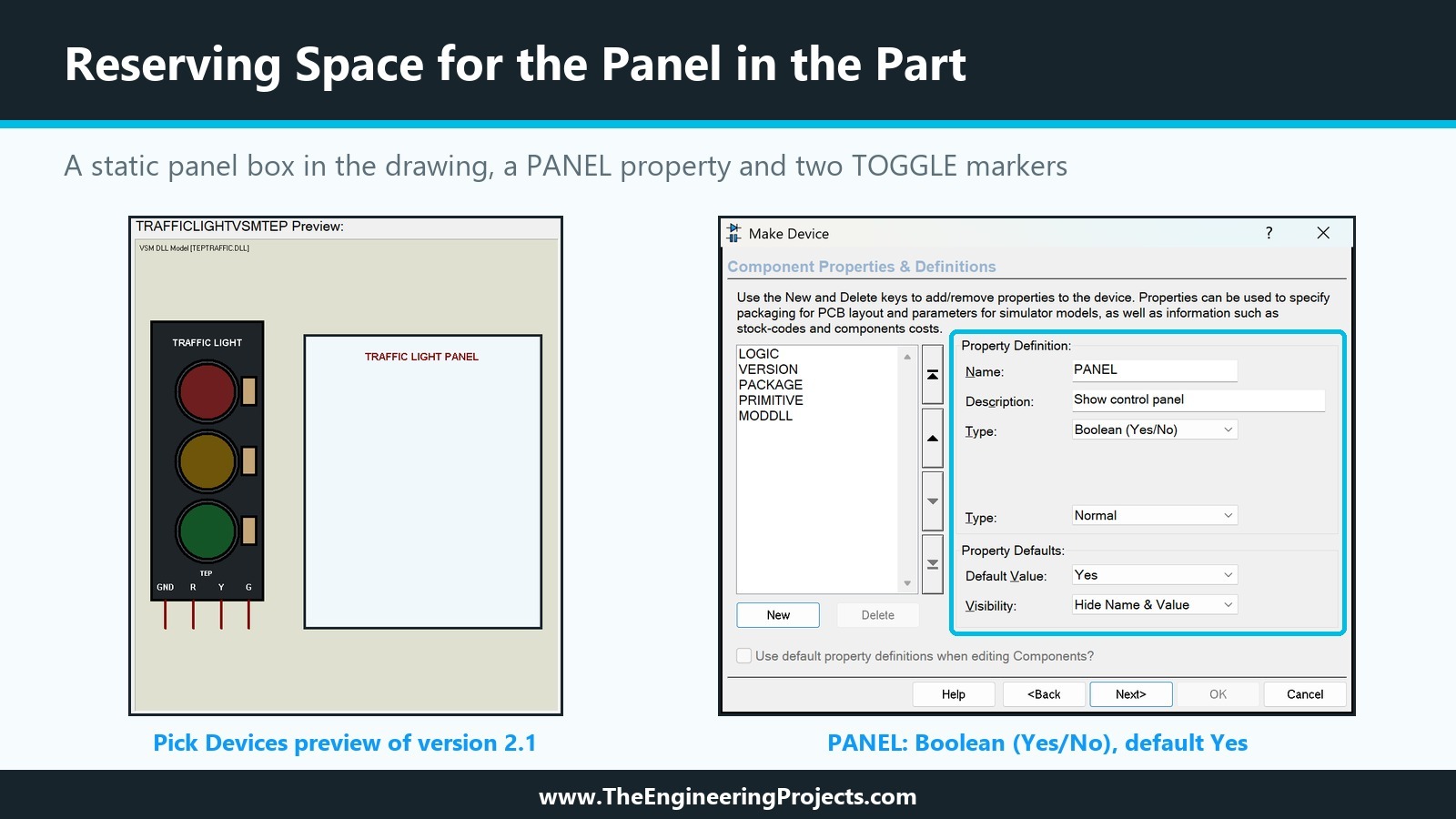
The panel is drawn by the model, but the part should show where it will appear, also in Pick Devices and in a design that is not simulating. So we placed a fresh TRAFFICLIGHTVSMTEP, decomposed it and drew a box in the 2D Graphics Box mode from 1000 to 2700 thou to the right of the origin and from 0 to 2100 thou above it, exactly the frame the model draws. In its Edit Style tab, we gave it the light fill 240, 248, 252 and the dark outline 23, 36, 43 of the drawn panel, and added the title TRAFFIC LIGHT PANEL as a 90th text at the top.
The PANEL Property
In Make Device, we added a Blank Item named PANEL with the description Show control panel, the type Boolean (Yes/No) and the default Yes, raised VERSION to 2.1 and stored the part again in TEPTUTORIAL, replacing version 2.0 and updating the placed instances. A user who does not want the panel can set it to No, and the model draws the module alone.
Step 4: Why the Clicks Did Nothing
The first run looked perfect. The panel appeared over the static box and showed RED pin HIGH lamp ON, YELLOW pin LOW lamp OFF, GREEN pin HIGH lamp ON and two lamp switch-ons. Then we clicked LOGIC, and nothing happened. A second click did not help either.
Finding the Cause
We built a debug version of the DLL that writes every call of actuate, with its position and flags, to a text file, installed it and clicked both buttons and the module itself during a run. The file stayed empty: Proteus never called actuate at all.
We found the answer in the subject of the sixteenth tutorial, the actuator markers. Our push button reacts to the mouse, and its drawing has a TOGGLE marker. Our traffic light had none. We could not find a statement about this in the help, so we tested it: with markers in the drawing, the clicks arrived, as the next step shows.
Adding the Markers
We decomposed the part once more and placed two TOGGLE markers at the right edge of the panel box, 2650 thou from the origin, one at the height of each button. Make Device stored the part again, still as version 2.1.
Step 5: One Click, Two Changes
Now the clicks arrived, but one click on LOGIC flipped it twice. The simulation log showed "panel set LOGIC to active LOW" and, a moment later in simulation time, "panel set LOGIC to active HIGH", and the panel ended where it started.
Proteus evidently called actuate more than once for a single press, so we added two guards, the same ones the source of our TEP RFID model has. The model ignores calls whose flags have the highest bit set, and it remembers that a button is held down and ignores further calls until the mouse button is released. After the next build, one click gave exactly one change.
How to Test the Live Control Panel
We tested the final version with the circuit of the previous tutorial: U2 with LOGICSTATE inputs R = 1, Y = 0 and G = 1, and GND on ground.
Before and After Run
Without a simulation, the part shows the panel with all pins OPEN, all lamps OFF and zero switch-ons, because the model draws it from the component's properties alone. After Run, the panel showed the live levels: R and G HIGH and lit, Y LOW and dark.
Switching LOGIC While the Simulation Runs
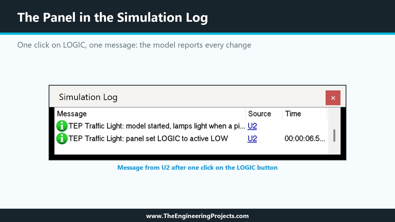
One click on LOGIC turned the button blue with the text LOGIC: ACTIVE LOW. Red and green went dark and yellow lit, with the pins unchanged, and the counter rose from two to three switch-ons. The simulation log showed one new line from U2.
Holding LAMP TEST
While we held the left mouse button on LAMP TEST, the button turned blue and all three lamps lit, both on the module and on the panel, and the counter showed five. When we released it, the module returned to the active low pattern with only yellow lit. This is a lamp test as real traffic controllers have it: a quick check that every lamp works, without touching the circuit.
What the Counter Is For
The counter counts every switch-on of every lamp since the start of the run. In the next tutorial, an Arduino drives our module, and a counter that grows faster than the sketch should switch lamps is a quick hint at flicker or a bug in the timing.
How to Design a Panel That Keeps the Simulation Fast
A panel is drawn while the simulation runs, so every decision about it costs simulation time. Four choices in our model keep the cost low, and they are worth copying for your own parts.
Send Data Only When It Changes
indicate compares the packed number with the last one it reported and returns FALSE when nothing changed. Proteus then has no reason to call animate, and the panel is not redrawn. In a sketch that switches a lamp once per second, the panel is redrawn a few times per second of simulation time, not on every timer callback.
Choose the Poll Interval
Our callback runs every 10 milliseconds of simulation time, which is a hundred times per simulated second. A human click lasts much longer than that, so no click is missed, and a hundred cheap callbacks per second are nothing compared with what a microcontroller model does in the same time. A much shorter interval would only cost time, and a much longer one would make the buttons feel slow when the simulation runs in real time.
Keep the Panel Inside Its Box
The model draws only inside the box we reserved in the part's drawing, from 1000 to 2700 thou to the right of the origin and from 0 to 2100 thou above it. Everything the model draws becomes part of the component's picture, so a panel that grows beyond the reserved area would overlap the wires and parts next to the module, which the user could not know about when placing it.
Make the Panel Optional
A design with several modules does not need a panel next to each of them. The PANEL property lets the user switch it off per module, and the model then draws only the lamps, exactly as in the previous tutorial. The model reads PANEL in initialize, when the editor creates the model for the placed part.
Common Mistakes When Adding a Control Panel
| Problem | Cause | Solution |
|---|---|---|
| Clicks on the panel do nothing | The part has no actuator marker, so actuate is never called | Add TOGGLE, INCREMENT or DECREMENT markers to the drawing |
| One click changes the setting twice | actuate is called more than once per press | Ignore repeat calls and latch the press until release |
| The new DLL cannot be copied | An open design with the part keeps the DLL loaded | Close every design that uses the DLL first |
| The panel never reacts during a run | No pin changes, so simulate is not called | Poll the panel with a timer callback |
| The panel is drawn in the wrong place | Coordinates not relative to the part's origin | Draw in thou from the origin with setdrawscale(1000) |
In the Next Tutorial
Our library now has a module with a C++ model and a live panel, and a push button from the sixteenth tutorial. In the next tutorial, How to Test a Custom Proteus Library with Arduino, we connect both to an Arduino UNO, run a real sketch on them and use the panel and the push button to test the sketch and the library together.
FAQ
Can a Proteus model draw its own graphics?
Yes. A model DLL linked to its part receives an ICOMPONENT interface with vector drawing services, and it can draw boxes, circles, lines and text in plot and animate.
Why does my Proteus model never receive mouse clicks?
In our tests, Proteus called actuate only after we added actuator markers to the part's drawing. Without a TOGGLE, INCREMENT or DECREMENT marker, the clicks never reached the model.
How does the panel talk to the simulator?
Through shared variables. Our model uses std::atomic values that the drawing side writes and the simulator side reads in a timer callback, and the simulator sends its data back through indicate.
Do I need a popup window for a control panel?
No. A panel drawn on the sheet needs only the drawing services. Popup windows are another option of the VSM interface, which our TEP Serial Monitor uses for a separate window.
That is all for today. Our Traffic Light Module now has a dashboard of its own, and you can change it with a click while the simulation runs. If you have any questions, ask in the comments. Take care.