Hello friends, I hope you are doing well. This is the nineteenth tutorial in our series on how to create a Proteus library. In the previous tutorial, How to Add a Live Control Panel to a Proteus Component, our Traffic Light Module learned to show its pins and lamps on a panel and to change its LOGIC setting with a click while the simulation runs. So far, we tested every part with logic switches. Today, we test the library the way its users will use it. Our topic is how to test a custom Proteus library with Arduino.
A library is only finished when it works with a real program. Logic switches show that a part reacts to its pins; a sketch on a simulated microcontroller shows that it reacts to them at the right speed, in the right order and together with other parts. We will build a test project with an Arduino UNO, our Traffic Light Module and our Push Button Module, write a small traffic light sketch with a pedestrian button, compile it to a HEX file, load it into the simulated Arduino and run three tests: the normal cycle, a button press and a deliberate configuration mistake.
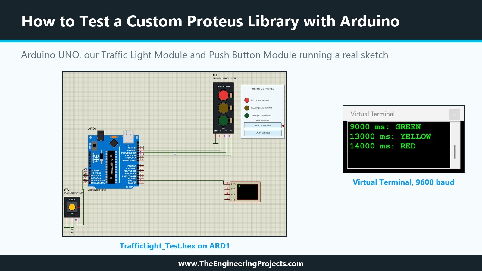
Everything shown here was done in Proteus 8.5 Professional on our PC. The picture below shows the test project during a run: the sketch has just switched to red, the Traffic Light Module shows it on its lamps and its panel, and the Virtual Terminal shows the sketch's own messages.
Why Test a Proteus Library with a Real Sketch?
In the earlier tutorials, we tested each part in isolation: lamp currents with ammeters, states with LOGICSTATE parts, the push button with a power terminal and the DLL model with logic switches. These tests are quick and precise, but they all come from us, the authors of the library, and we know which inputs the parts expect.
What a Sketch Adds
A sketch drives the parts like a user's project does. It changes several pins within microseconds of each other, it reads the button at its own pace, and it runs for minutes instead of seconds. A model that handles every single input correctly can still fail in such a run, for example when it misses a quick sequence of changes or reports a state too late. And the person who downloads a library will almost certainly connect it to an Arduino first.
What We Want to Find Out
Our test answers four questions. Does the Traffic Light Module follow the Arduino's pins exactly, phase by phase? Does the Push Button Module give the Arduino a clean HIGH and LOW, with no floating input? Does the timing of the sketch arrive unchanged on the lamps? And can a user tell, from what the simulation shows, whether a problem lies in the sketch or in the library?
What You Need for the Test
Besides our two parts from TEPTUTORIAL, the test needs three things.
An Arduino UNO for Proteus
On our PC, Pick Devices offered the ATmega328P microcontroller, but a search for ARDUINO found only connectors, an audio shield element and Grove parts, no Arduino board. We used our own TEP Arduino UNO V3, which comes with every TEP library package as ArduinoV3TEP.LIB. We copied ArduinoV3TEP.LIB and ArduinoV3TEP.IDX from one of our packages into the LIBRARY folder of Proteus. Pick Devices listed the new board only after we restarted Proteus; a search for ARDUINO then showed ARDUINO UNO V3.0 from the library ArduinoV3TEP, described as Arduino UNO R3 V3.0 designed by www.TheEngineeringProjects.com.
A Virtual Terminal
The Virtual Terminal is one of Proteus's instruments, in the Virtual Instruments mode of the left toolbar. It shows what the Arduino sends on its serial TX pin. We use it as the sketch's diary: every phase change is printed with the time in milliseconds.
A Compiled Sketch
Proteus does not compile Arduino sketches by itself; the simulated Arduino runs a HEX file, the same machine code that would be uploaded to a real board. With the Arduino IDE, Sketch, Export Compiled Binary writes such a file next to the sketch. On our PC, we compiled with the AVR GCC compiler and the Arduino AVR core 1.8.6 for an ATmega328P at 16 MHz, the toolchain behind the IDE's UNO support.
The Test Sketch
Our sketch is a small traffic light controller: four seconds green, one second yellow, four seconds red, and again. A pedestrian button cuts the green phase short: if it is pressed while the light is green, green ends after at least one second, and the light changes to yellow and then red. Here is the complete sketch, TrafficLight_Test.ino:
// TEP tutorial 19: testing our Traffic Light Module and Push Button Module with an Arduino UNO
// The Engineering Projects - www.TheEngineeringProjects.com
//
// Traffic Light Module: R -> D12, Y -> D11, G -> D10, GND -> GND
// Push Button Module  : OUT -> A0, VCC -> 5V, GND -> GND (the module has its own pull-down)
// Serial output       : TX (D1) -> Virtual Terminal RXD, 9600 baud
// A press during green asks for a pedestrian phase: green ends early, then yellow and red.

const byte RED_PIN = 12;
const byte YELLOW_PIN = 11;
const byte GREEN_PIN = 10;
const byte BUTTON_PIN = A0;

// HIGH for a module whose lamps light on a HIGH pin (LOGIC = High).
// Change to LOW for a module whose lamps light on a LOW pin (LOGIC = Low).
const byte LAMP_ON = HIGH;

const unsigned long GREEN_TIME = 4000;    // milliseconds
const unsigned long MIN_GREEN = 1000;     // green stays at least this long after a press
const unsigned long YELLOW_TIME = 1000;
const unsigned long RED_TIME = 4000;

enum Phase { GREEN, YELLOW, RED };
Phase phase = GREEN;
unsigned long phaseStart = 0;
bool requested = false;
bool lastButton = false;

void setLamp(byte pin, bool on) {
  digitalWrite(pin, on ? LAMP_ON : !LAMP_ON);
}

void showPhase(Phase p) {
  setLamp(RED_PIN, p == RED);
  setLamp(YELLOW_PIN, p == YELLOW);
  setLamp(GREEN_PIN, p == GREEN);
  Serial.print(millis());
  Serial.print(" ms: ");
  Serial.println(p == RED ? "RED" : p == YELLOW ? "YELLOW" : "GREEN");
}

void startPhase(Phase p) {
  phase = p;
  phaseStart = millis();
  showPhase(p);
}

void setup() {
  pinMode(RED_PIN, OUTPUT);
  pinMode(YELLOW_PIN, OUTPUT);
  pinMode(GREEN_PIN, OUTPUT);
  pinMode(BUTTON_PIN, INPUT);
  Serial.begin(9600);
  Serial.println("TEP traffic light test");
  startPhase(GREEN);
}

void loop() {
  const bool button = digitalRead(BUTTON_PIN) == HIGH;
  if (button && !lastButton && phase == GREEN && !requested) {
    requested = true;
    Serial.println("Button pressed: pedestrian request");
  }
  lastButton = button;

  const unsigned long elapsed = millis() - phaseStart;
  switch (phase) {
    case GREEN:
      if (elapsed >= GREEN_TIME || (requested && elapsed >= MIN_GREEN)) {
        requested = false;
        startPhase(YELLOW);
      }
      break;
    case YELLOW:
      if (elapsed >= YELLOW_TIME) startPhase(RED);
      break;
    case RED:
      if (elapsed >= RED_TIME) startPhase(GREEN);
      break;
  }
}
Pins and Wiring
The comment at the top of the sketch is the wiring plan. The module's R, Y and G go to D12, D11 and D10, and its GND to ground. The button's OUT goes to A0, used as a digital input, its VCC to +5V and its GND to ground. The Arduino's TX pin, D1, goes to the RXD input of the Virtual Terminal.
No Pull-Down in the Sketch
The sketch sets the button pin as a plain INPUT, without the internal pull-up. It does not need one, because our Push Button Module has its own 10k pull-down resistor, the RPULL property from the sixteenth tutorial. This is exactly the kind of detail a library test should confirm: if the module's pull-down did not work, the input would float while the button is released, and the sketch could see false presses.
The LAMP_ON Constant
LAMP_ON says which level lights a lamp. It is HIGH for our module with LOGIC set to High. A user with an active-low module changes it to LOW, and setLamp writes the opposite level for a lamp that should be off. We come back to it in the third test.
Reading the Button Once per Press
The sketch compares the button with its previous reading and reacts only to the change from LOW to HIGH, and only during green. One press gives one request, however long the button is held, and a press during yellow or red is ignored.
Which Version of the Module to Test
Our library has two versions of the Traffic Light Module, and they answer different questions.
TRAFFICLIGHTTEP: the Analogue Version
The version from the fourteenth and fifteenth tutorials uses a schematic model with resistors, LEDs and current probes. It shows real currents in ammeters, honours the resistor properties RRED, RYEL and RGRN, and lights a lamp only when enough current flows. It is the right part for questions about the electrical side, such as whether an Arduino pin can drive the module with a given resistor.
TRAFFICLIGHTVSMTEP: the DLL Version
The version from the last two tutorials uses TEPTRAFFIC.DLL. It is purely digital, honours LOGIC and has the control panel. It is the right part for questions about the program: which pin is driven when, and whether the module and the sketch agree. Our test is about the program, so we used this version.
How to Test a Custom Proteus Library with Arduino: Step by Step
We built and ran the test in five steps.
Step 1: Create a Test Project
We created a new project, TrafficLight-Arduino-Test, in the same folder as our other projects, with a schematic and no PCB layout or firmware project, and placed the ARDUINO UNO V3, a TRAFFICLIGHTVSMTEP, a PUSHBUTTONTEP and a Virtual Terminal. A test project of its own keeps the library test separate from the projects we used to build the parts.
Step 2: Wire It as the Sketch Says
We wired the parts exactly as in the comment of the sketch, with ground terminals for the module and the button and a power terminal labelled +5V for the button's VCC. Proteus connects terminals with the same name, so the ground terminals need no wire between them.
Step 3: Load the HEX File
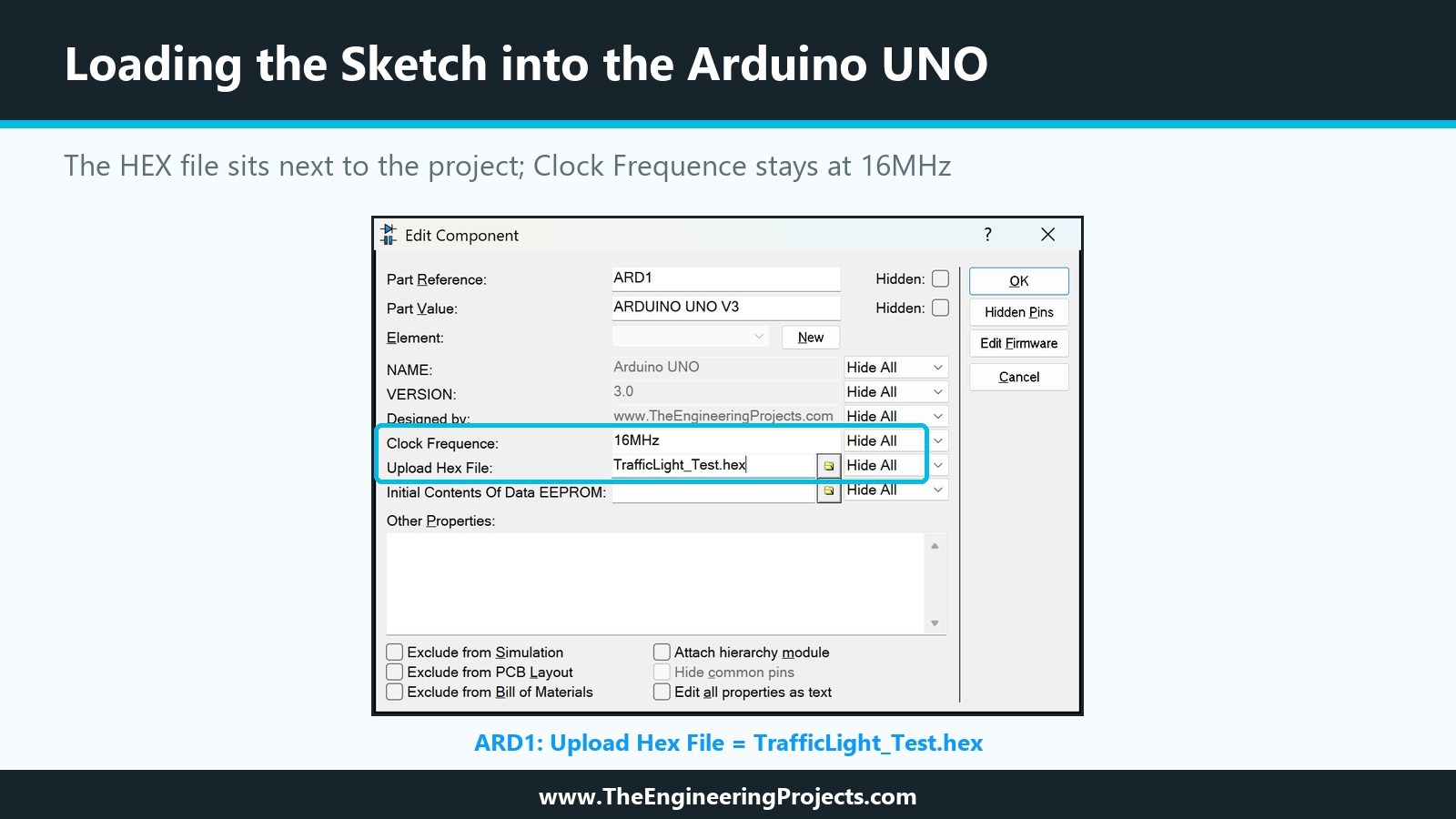
In the Edit Component dialogue of ARD1, the Upload Hex File property takes the program. We typed the file name TrafficLight_Test.hex and copied the file into the project's folder, so the project and its program stay together. The Clock Frequence property stays at 16MHz, the clock the sketch was compiled for.
Step 4: Run and Watch
After Run, the Virtual Terminal opened and printed the phases as the sketch reached them, and the module followed. We describe the results in the next section.
Step 5: Pause to Hit the Right Moment
A test sometimes needs an action at a specific moment, like pressing the button during green. The Pause button of the animation controls stops the simulation clock, so we can wait for the phase we want, pause, prepare the action and continue.
The Test Results
We ran the project several times. These are the results of the three tests, with the times printed by the sketch.
Test 1: The Normal Cycle
The terminal printed 0 ms: GREEN, 4000 ms: YELLOW and 5000 ms: RED, then 9000 ms: GREEN, 13000 ms: YELLOW, 14000 ms: RED and so on, a cycle of exactly nine seconds of simulation time. Whenever we looked, the module showed exactly one lamp, the one of the current phase. The panel confirmed it from the other side, for example RED pin HIGH lamp ON with YELLOW and GREEN pin LOW lamp OFF during red, and its counter matched the number of phases: 24 switch-ons when the 24th phase had started.
Simulation Time, Not Clock Time
The times on the terminal come from millis() in the sketch, and the simulated Arduino counts simulation time. On a slow PC, nine seconds of simulation can take longer than nine seconds on the wall clock, and the status bar of Proteus shows the current simulation time and the CPU load during a run. The printed times are therefore exact for the program, whatever the speed of the computer, which makes them a reliable basis for timing tests.
Test 2: A Pedestrian Request
We paused the simulation when the terminal had just printed 63000 ms: GREEN, clicked the TOGGLE marker of the push button to latch it, the method from the sixteenth tutorial, and continued. The terminal printed Button pressed: pedestrian request, followed by 65784 ms: YELLOW and 66784 ms: RED. Without the request, yellow would have started at 67000 ms. Green ended early, after more than the minimum of one second, and the following phases kept their normal lengths.
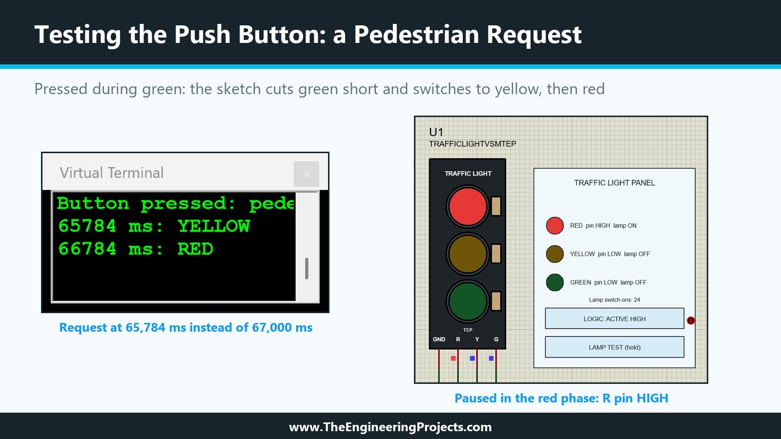
The test also confirmed the button module's pull-down. Every green phase before the press lasted the full four seconds, so the sketch never saw a false press while the button was released, and while it was latched, the sketch reported exactly one request, so it saw one clean edge. We released the button with a second click on its marker.
Test 3: A Mismatch Between Sketch and Module
For the last test, we made a deliberate mistake. While the simulation was running, we clicked LOGIC on the module's panel and switched the module to active low, while the sketch still had LAMP_ON set to HIGH. At 70784 ms, the terminal printed GREEN, but the module lit red and yellow and left green dark.
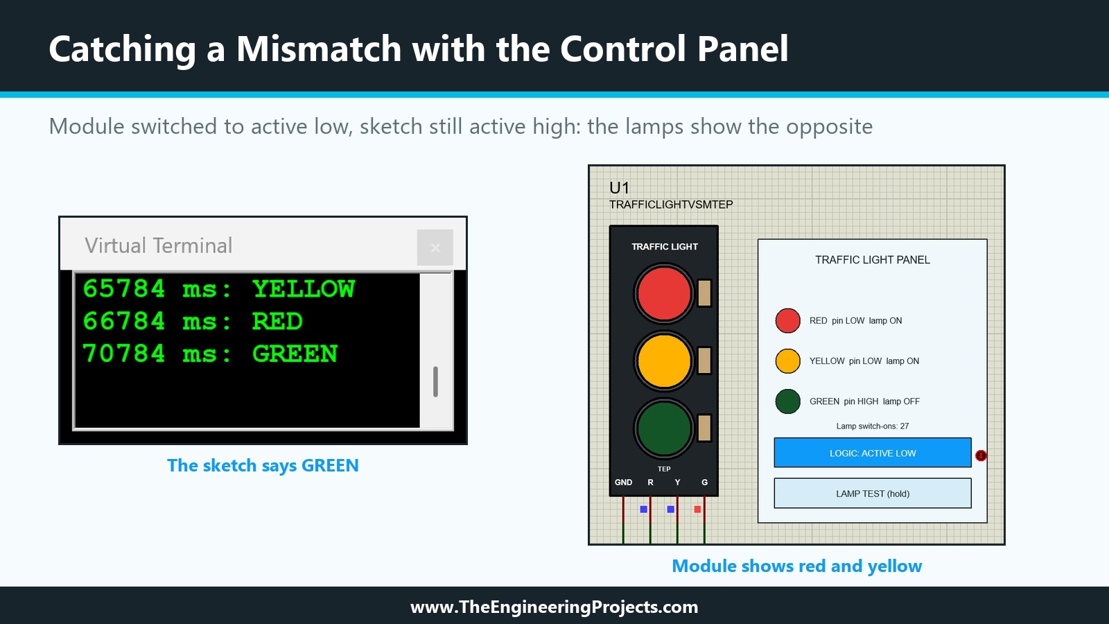
This is the situation the panel was made for. A user who sees the wrong lamps cannot tell from the module alone whether the sketch or the library is at fault. The panel answers it at a glance: GREEN pin HIGH, RED and YELLOW pins LOW, so the sketch drives the pins correctly, and LOGIC: ACTIVE LOW explains why the lamps show the opposite. The fix is either LOGIC back to High or LAMP_ON set to LOW in the sketch.
A Test Plan for Your Own Library
Our three tests follow a pattern that works for most parts. Before you publish a library, run at least these checks with a real sketch.
| Check | How we did it | What to look for |
|---|---|---|
| Every pin works | Each phase drives a different pin | The part reacts to each pin, and only to it |
| Timing arrives unchanged | Times printed on the Virtual Terminal | Phase lengths in the simulation match the sketch |
| Inputs are clean | Button read once per press | No false presses while released |
| Interaction during a run | Button latched at a chosen moment | The sketch sees the action at once |
| Wrong configuration | LOGIC changed against the sketch | The part makes the mistake visible |
Keep the Test Project with the Library
A test project is worth keeping. When you change a model in a later version, the same project and HEX file show at once whether the parts still behave as before. In the next tutorial, the test project becomes part of the package we share.
Common Mistakes When Testing a Proteus Library with Arduino
| Problem | Cause | Solution |
|---|---|---|
| The Arduino part is not in Pick Devices | New library files are read at start-up | Restart Proteus after copying the LIB and IDX files |
| Nothing happens after Run | No program in Upload Hex File, or the file is not found | Put the HEX file next to the project and enter its name |
| The timing is wrong | Clock Frequence differs from the compiled clock | Keep 16MHz for a sketch compiled for the UNO |
| Garbage on the Virtual Terminal | Baud rates differ | Use the sketch's rate, 9600 in ours, on the terminal |
| The button press is missed | Pressed outside the phase that reads it | Pause in the right phase, latch the button, continue |
| The lamps show the opposite of the sketch | LOGIC and LAMP_ON do not match | Check the panel: pin levels right, LOGIC wrong |
In the Next Tutorial
Our library is built and tested: a Traffic Light Module in two versions, a Push Button Module, their models, a C++ DLL with a panel, a test sketch and a test project. In the final tutorial of the series, How to Package and Share Your Own Proteus Library, we clean up the library files, collect everything a user needs into one package and check that it installs on another PC.
FAQ
Can I test a custom Proteus library without real hardware?
Yes. A simulated Arduino runs the same HEX file as a real board, so a sketch can drive your parts in Proteus exactly as it would drive the real modules.
How do I load an Arduino sketch into Proteus?
Compile the sketch to a HEX file, for example with Sketch, Export Compiled Binary in the Arduino IDE, and enter the file in the Arduino part's program property, Upload Hex File on our TEP Arduino UNO V3.
Why does Proteus not show my new Arduino library?
On our PC, Pick Devices showed a newly copied library only after a restart of Proteus.
How can I press a button at an exact moment in a Proteus simulation?
Pause the simulation in the phase you need, latch the button with its marker and continue. The sketch sees the press as soon as the simulation runs again.
That is all for today. Our library has passed its first real test with an Arduino, and the control panel has already earned its place. If you have any questions, ask in the comments. Take care.