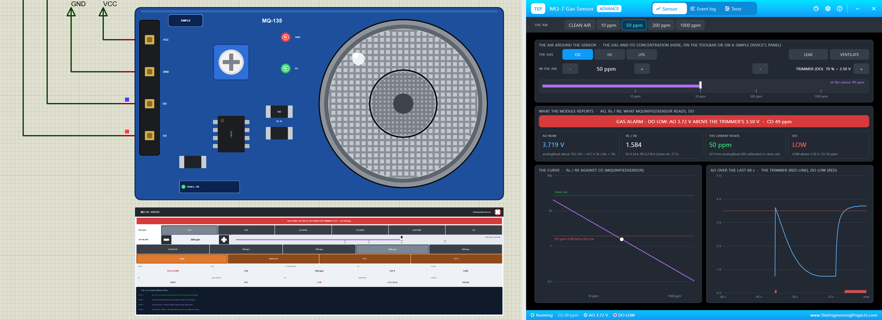
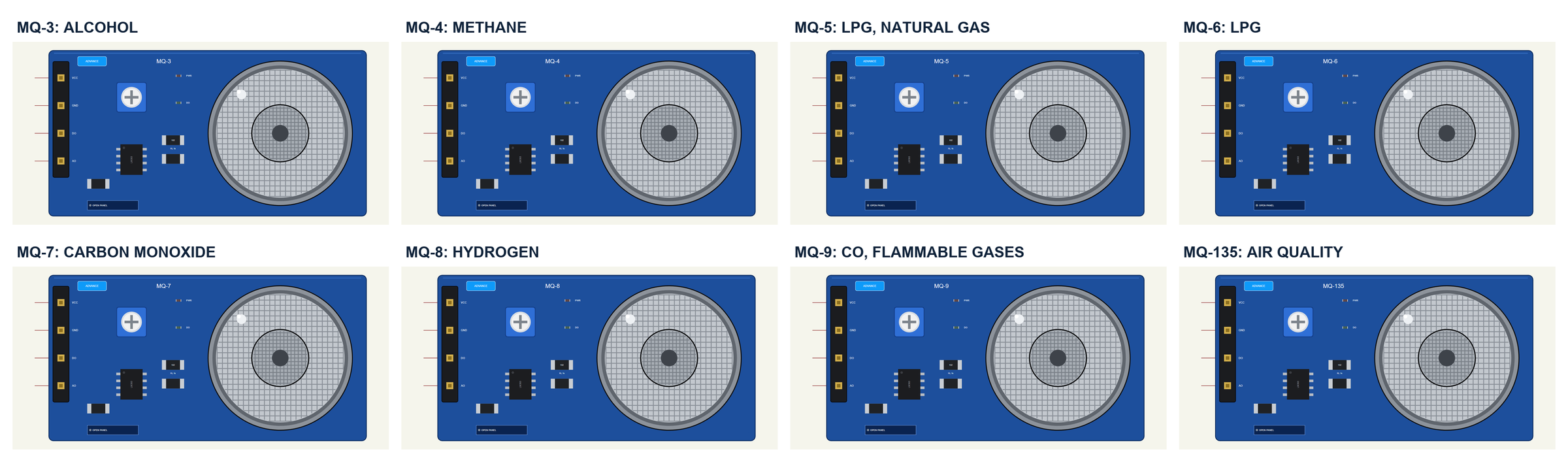
Hello friends, I hope you all are doing great. Today, I am going to share the new MQ Gas Sensor Library for Proteus V1.0, with eight of the popular MQ sensors in one package: the MQ-3 (alcohol), MQ-4 (methane), MQ-5 and MQ-6 (LPG), MQ-7 (carbon monoxide), MQ-8 (hydrogen), MQ-9 (CO and flammable gases) and MQ-135 (air quality). They sit on the same small blue module with an analog output and a digital alarm, and now you can test your gas alarm, breathalyser or air-quality meter in Proteus before you solder anything.
Behind the parts sits our own model, built on the curves of MQUnifiedsensor, the Arduino library most makers use with these sensors - so a sketch with that library reads back the gas you set. The heater warms up, the gas reaches the sensor with a delay, the trimmer sets the alarm, and every sensor reacts to more than its own gas, just like the real ones. You get sixteen devices: for each sensor a Simple device with a live STATUS panel and an Advance device with a pop-up window and the test tools. The demo runs on our Arduino UNO V4.0.
NOTICE: a gas sensor is easy to fake: a slider that moves a voltage. We wanted more. Our MQ sensors follow the same curves as the library you will use, warm up like the real ones, and get fooled by the wrong gas - so a sketch that never calibrates, calibrates too early or trusts the wrong curve fails exactly as it does with a real module. It took our team a lot of hard work. Your feedback is the fuel that keeps us going, so please tell us what you think in the comments below or in the MQ gas sensors board of our forum. And if our free libraries help you, you can buy us a coffee. So, let's get started with the MQ Gas Sensor Library for Proteus V1.0:
What are the MQ Gas Sensors?
An MQ sensor is a tiny ceramic tube coated with tin dioxide (SnO2) and heated to a few hundred degrees by a coil inside it. In clean air the hot coating has a high resistance, Rs; gases that burn or react on its surface lower it. Each MQ type has a coating and a temperature tuned for its gas - but none of them sees only that gas. You can read more in our MQ gas sensor series overview and in the need for intelligent gas sensors. The MQ-2 has its own library already: our Gas Sensor Library for Proteus V2.0.
| Sensor | Made for | The model's gases | Read more |
|---|---|---|---|
| MQ-3 | alcohol - a breathalyser | ALCOHOL, BENZENE, HEXANE, LPG, CO (mg/L) | MQ-3 |
| MQ-4 | methane - natural gas | CH4, LPG, ALCOHOL | MQ-4 |
| MQ-5 | LPG and natural gas | LPG, CH4, H2, ALCOHOL, CO | MQ-5 |
| MQ-6 | LPG - butane and propane | LPG, CH4, H2, ALCOHOL | MQ-6 |
| MQ-7 | carbon monoxide (CO) | CO, H2, LPG | MQ-7 |
| MQ-8 | hydrogen (H2) | H2, ALCOHOL, LPG | MQ-8 |
| MQ-9 | CO and flammable gases | CO, LPG, CH4 | MQ-9 |
| MQ-135 | air quality - CO2, NH3, alcohol | CO2, NH3, ALCOHOL, TOLUENE, ACETONE, CO | MQ-135 |
The Module: AO and DO
The sensor sits on a small blue board with a 4-pin header. Rs and the board's load resistor RL (the 1 kOhm marked 102) form a divider, so the analog output is AO = VCC x RL / (Rs + RL): more gas, lower Rs, higher AO. An LM393 comparator compares AO with a blue trimmer, and its output DO goes LOW (and the DO LED lights) when AO passes the threshold - a ready-made alarm without any maths.
From Rs/R0 to ppm
The datasheets do not give a formula, but a chart: the ratio Rs/R0 against the gas, where R0 is the sensor's resistance at a reference. MQUnifiedsensor turns each chart into a power law - the gas = a x (Rs/R0)^b - and gives the ratio in clean air for each sensor, e.g. 3.6 for the MQ-135 and 27.5 for the MQ-7. So a sketch needs R0 first: it measures Rs in clean air and divides by that ratio. After that, every reading is a ratio and a curve. Our model uses exactly those numbers, so the library reads back what you set on the panel.
What's New in MQ Gas Sensor Library for Proteus V1.0
- Eight sensors, sixteen devices: the MQ-3, MQ-4, MQ-5, MQ-6, MQ-7, MQ-8, MQ-9 and MQ-135, each as a Simple and an Advance device, all in one model.
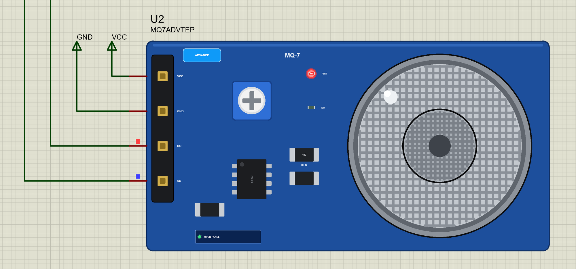
- The real module: the blue board with its header (VCC, GND, DO, AO), the trimmer, the LM393, RL (102), the PWR and DO LEDs and the sensor's steel mesh cap; the type is printed on the board.
- MQUnifiedsensor's curves: up to six gases per sensor with the library's a and b, and its clean-air ratios - a mixture adds the gases' conductances.
- The behaviour of a real sensor: the heater's warm-up (AO starts high, a false alarm), the delay of the gas (3 s up, 10 s down), the noise, and DO from the comparator without hysteresis.
- The air on the panel: the gas, its concentration (- / + and a log ruler), five presets, LEAK, VENTILATE and the trimmer.
- Three test tools on the Advance devices: Calibration & R0, Gas curves, and DO & heater.
- A two-node demo on our Arduino UNO V4.0 with MQUnifiedsensor: the warm-up, R0 in clean air, readings every second and the GAS, TYPE and CAL commands.
- A compact package: about 1.31 MB, without the C++ source code of the model.
Sixteen Devices: Simple and Advance
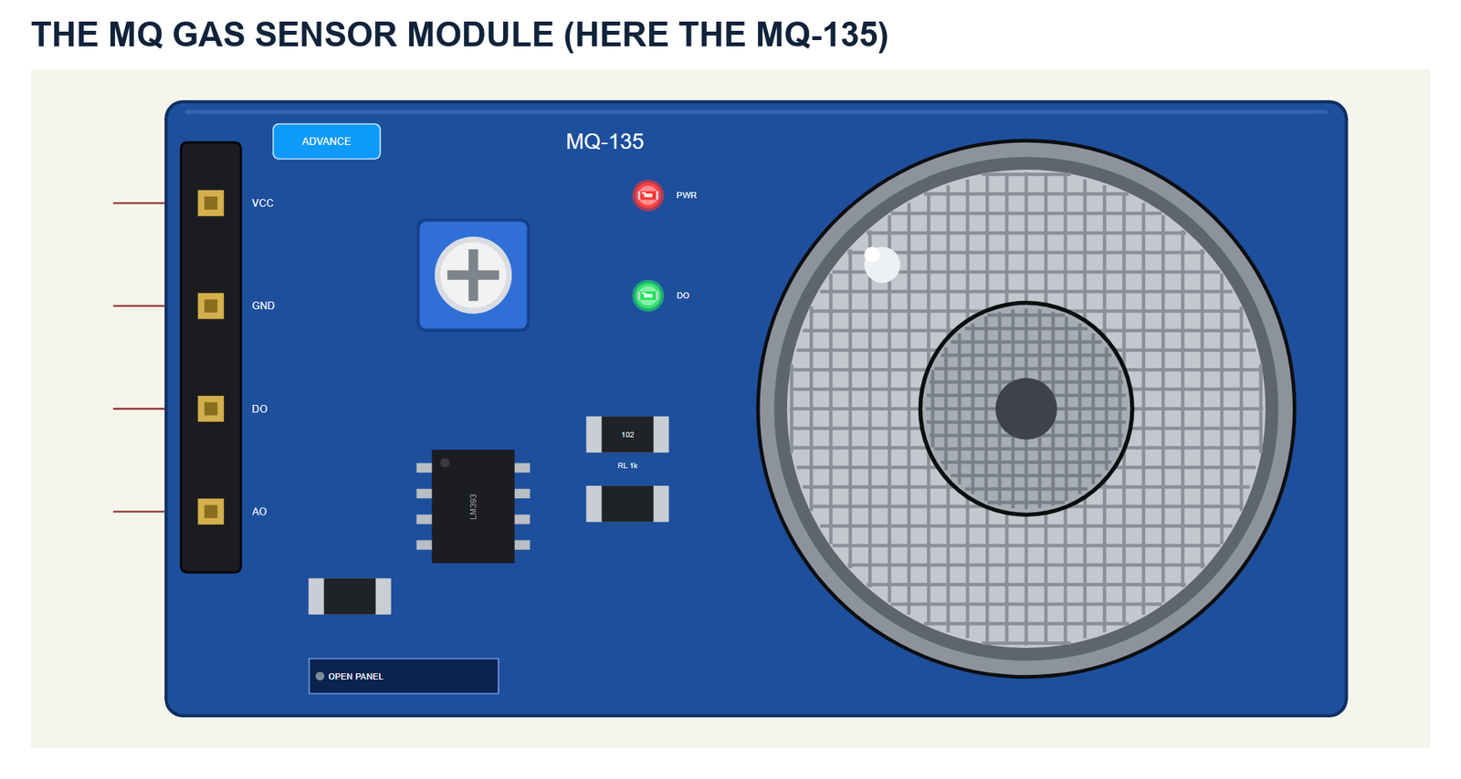
On the left is the header with VCC, GND, DO and AO; these are the part's pins. Next come the blue trimmer for the alarm threshold, the LM393, the load resistor RL with 102 on it, and on the right the sensor's round steel mesh cap. The PWR LED is on while the module has power; the DO LED lights with the alarm. The module is drawn at about three times its real size.
| Simple | Advance | |
|---|---|---|
| Devices | MQ3TEP ... MQ135TEP | MQ3ADVTEP ... MQ135ADVTEP |
| On the schematic | The module and the STATUS panel | The module |
| The gas and the actions | On the STATUS panel | In the pop-up |
| Status | Banner, a log ruler, 10 readouts, the last 4 events | A pop-up: Sensor, Event log, Tests |
Download MQ Gas Sensor Library for Proteus
Click the button below to download MQ-Gas-Sensor-Library-for-Proteus-v1.0.zip (about 1.31 MB, without the C++ source code of the model):
MQ Gas Sensor Library for Proteus V1.0- README.txt: the devices, installation, the demo, wiring, the test tools and real hardware.
- Proteus Library Files:
TEPMQGAS.LIBandArduinoV4TEP.LIBfrom our Arduino Library for Proteus V4.0. - Proteus Model Files:
TEPMQGAS.DLLandTEPARDUINO.DLL. - Proteus Simulation:
MQ-Gas-Sensors-ArduinoUnoV4.pdsprj,MQ_Gas_Demo.hexand copies of the two DLLs. - Arduino Code:
MQ_Gas_Demo.ino- it needs MQUnifiedsensor from the Library Manager to rebuild it.
No Proteus yet? Read How to Download and Install Proteus 7 and 8. New to libraries? Follow How to Install a New Library in Proteus.
How to Install MQ Gas Sensor Library for Proteus
- Close Proteus and extract the whole zip file, for example to your Desktop.
- Copy the two files from Proteus Library Files into the LIBRARY folder of Proteus (usually
C:\Program Files (x86)\Labcenter Electronics\Proteus 8 Professional\LIBRARY). - Copy
TEPMQGAS.DLLandTEPARDUINO.DLLfrom Proteus Model Files into the MODELS folder. - Delete
TEPMQGAS.IDXfrom the LIBRARY folder if it is there. - Start Proteus, press P and search for MQ (or MQ135, MQ7 ...).
Tip: keep the Proteus Simulation folder together, because the project needs its .hex file and the DLLs beside it. The library is tested in Proteus 8.5; Proteus 7 is not supported.
The MQ Parts in Proteus
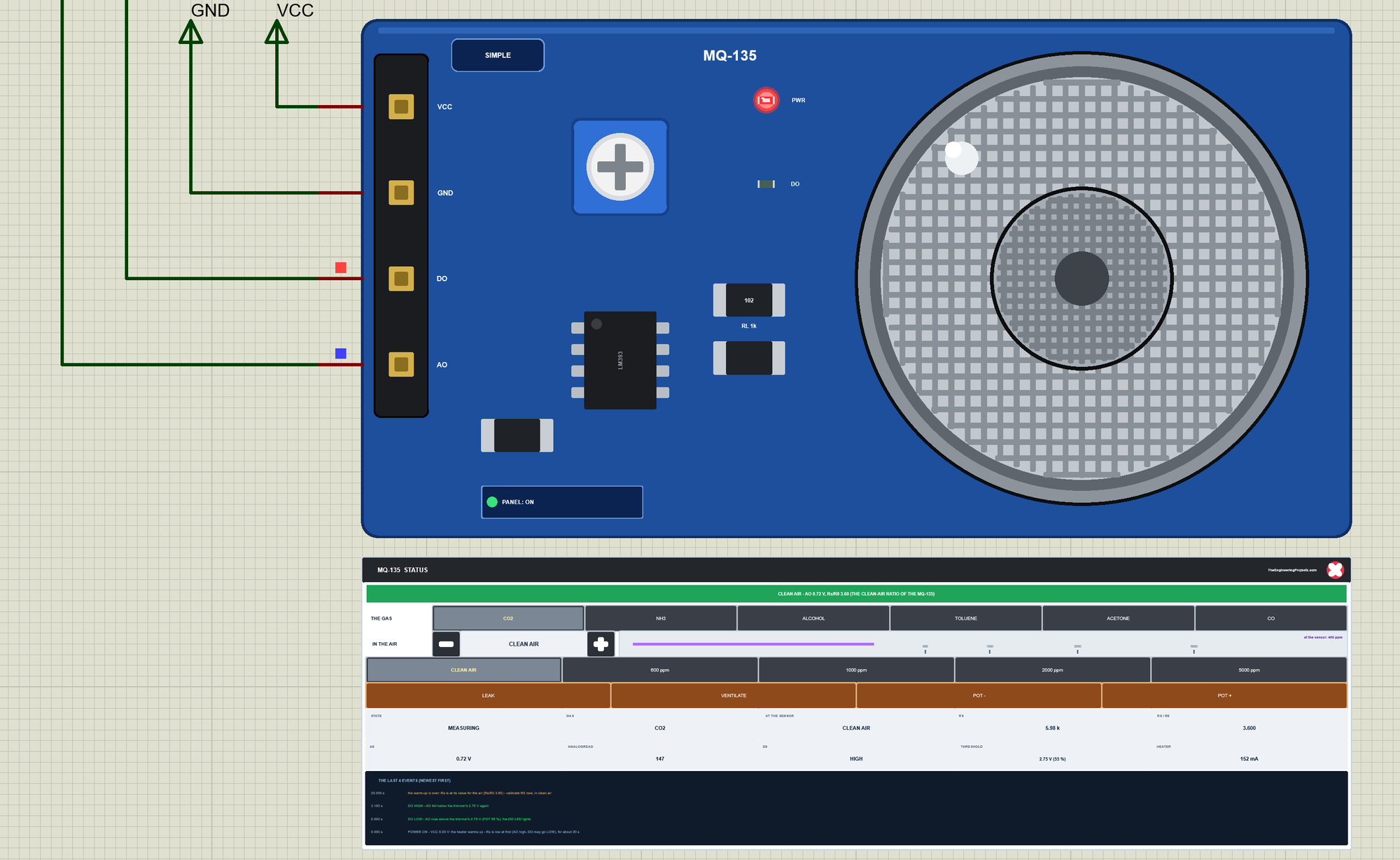
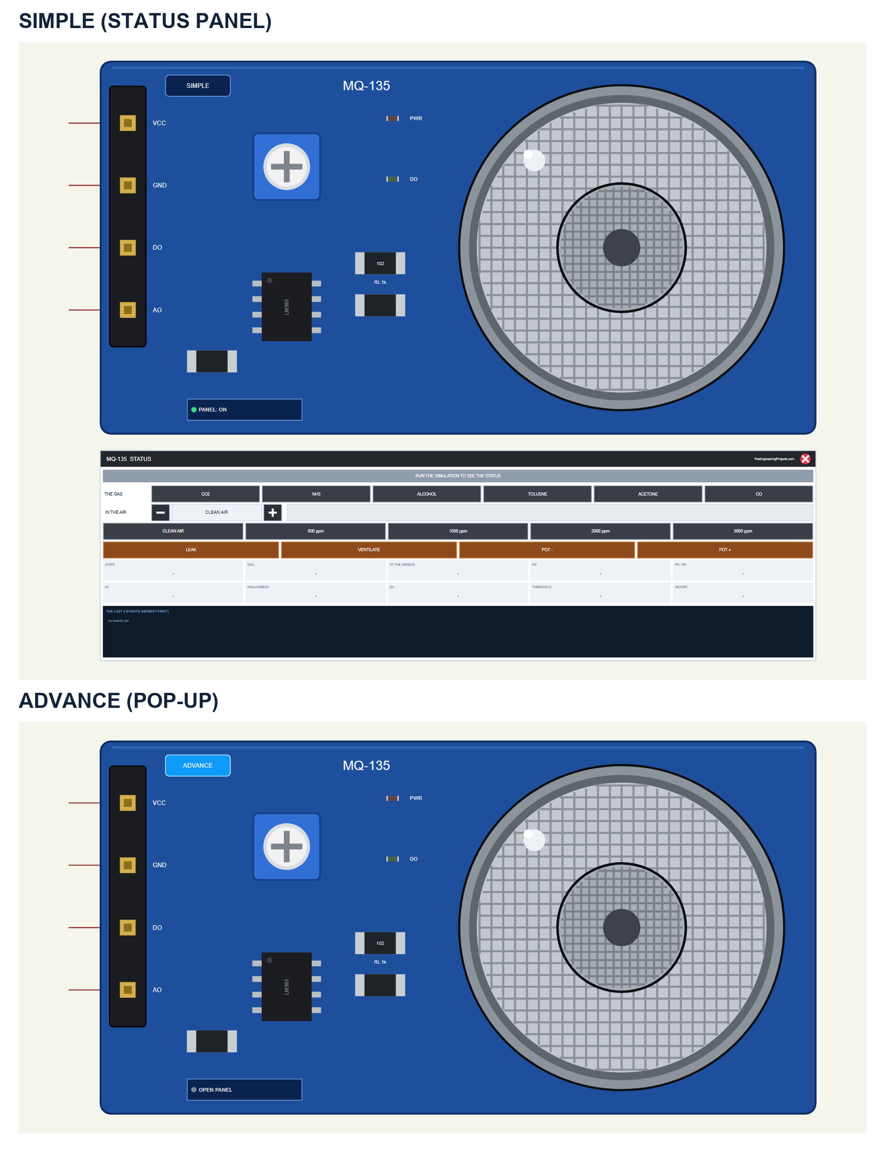
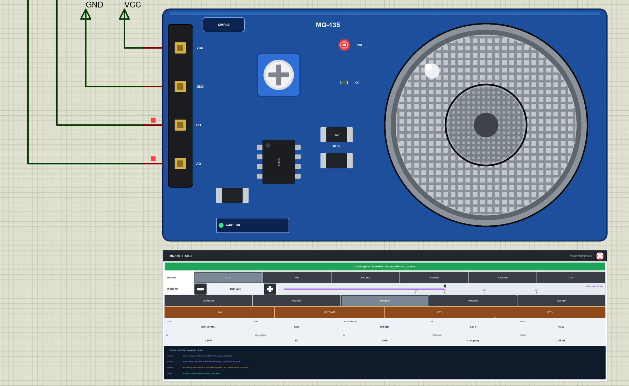
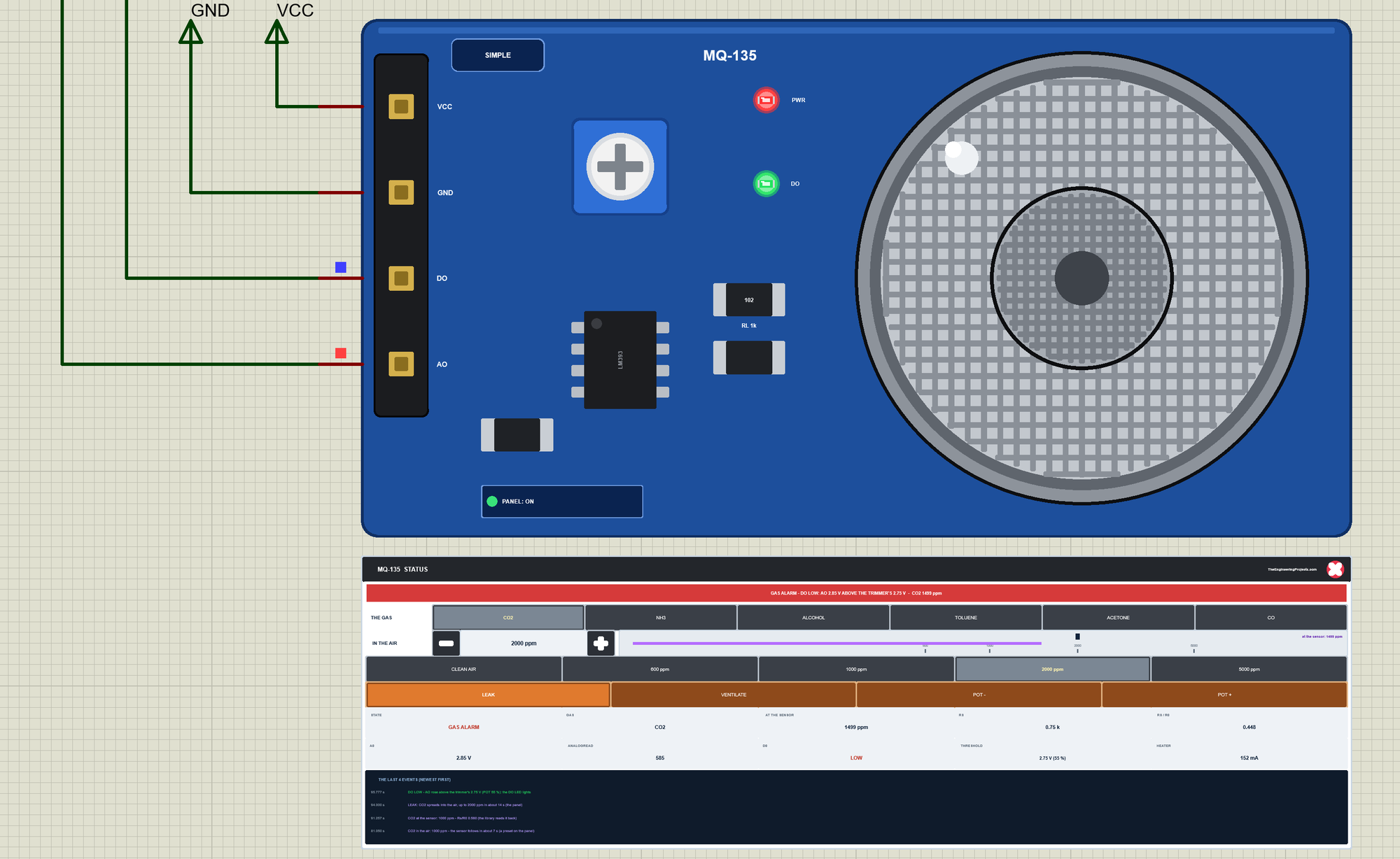
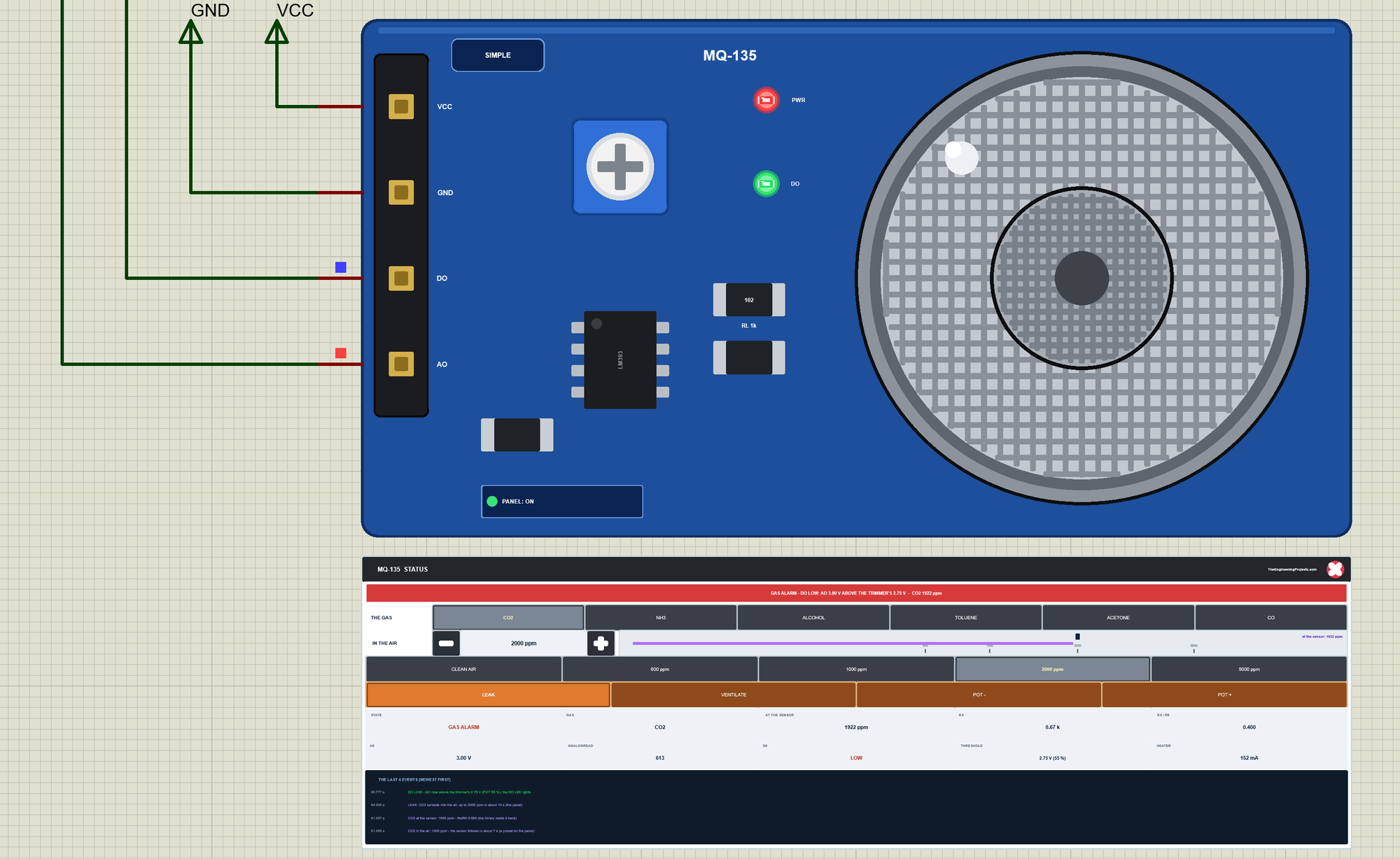
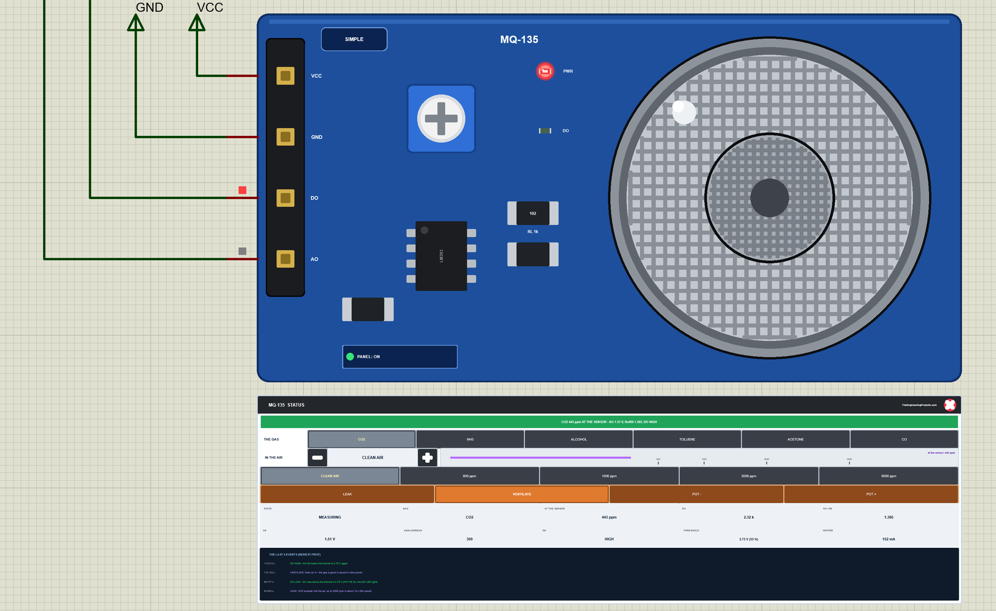
The Simple device adds the STATUS panel. Its banner says what the sensor sees: green for clean air or a gas below the alarm, amber while the heater warms up, and red for a GAS ALARM when DO is LOW. Below it are the controls: THE GAS with the sensor's gases, IN THE AIR with - and + (steps of 1.25 times) and a log ruler with the presets, the gas in the air and the gas at the sensor; five presets - CLEAN AIR and four levels of the gas; and four actions - LEAK, VENTILATE, POT - and POT +. Ten readouts follow - the state, the gas, the gas at the sensor, Rs, Rs/R0, A0, analogRead, D0, the threshold and the heater - and the last four events. The badge, the button and the panels are TEP additions.
The red X closes the STATUS panel, and the PANEL button on the board opens it again:
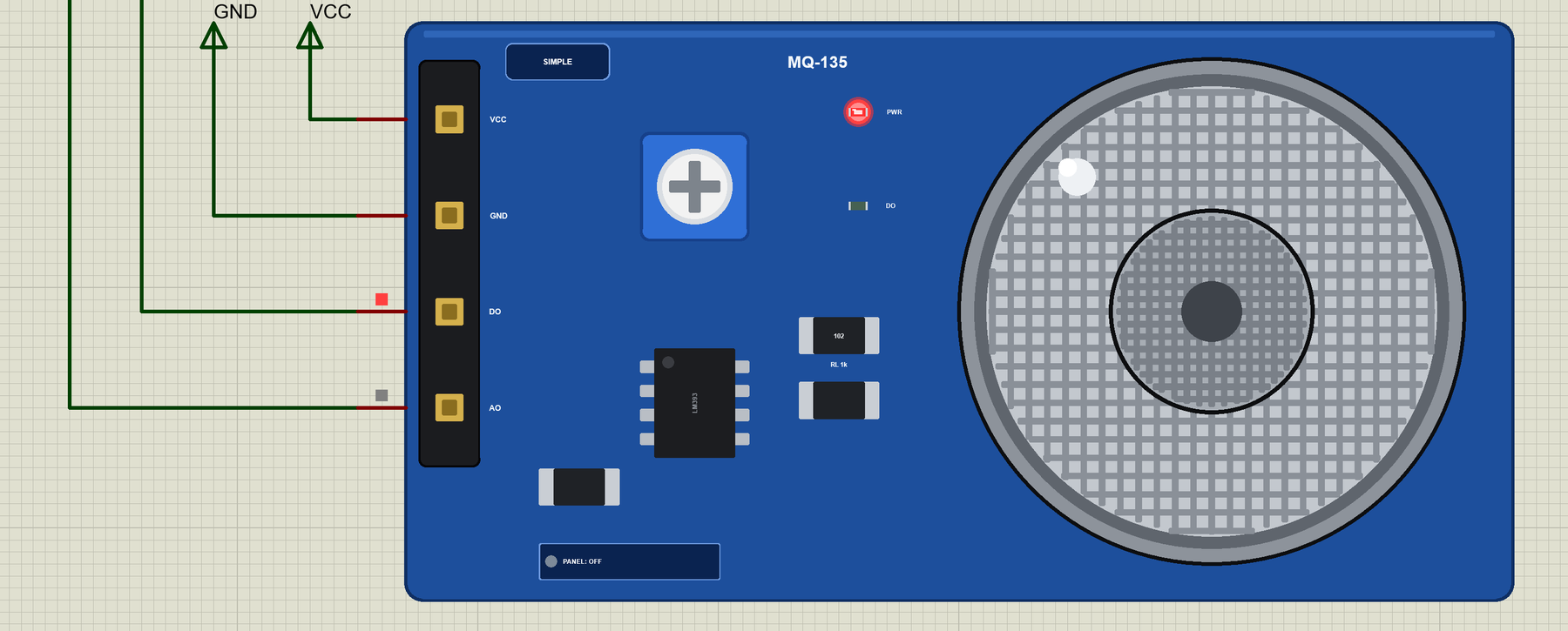
The Advance devices keep the schematic clean: only the module. The live data opens in a pop-up window at Run, and the OPEN PANEL button on the board brings the window back. The properties set the start: GAS and CONC (the gas in the air), POT (the trimmer in %), WARMUP (20 s) and NOISE (1 %).
The Demo Circuit
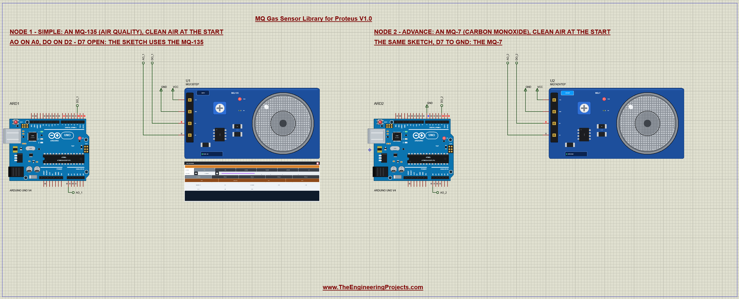
The demo project has two nodes, each an Arduino UNO V4.0 from our Arduino UNO Library for Proteus V4.0 with an MQ module. On both, AO goes to A0 and DO to D2. Node 1 is an MQ-135 with the trimmer at 55 % - DO LOW above about 1250 ppm of CO2. Node 2 is an MQ-7 with the trimmer at 70 % - DO LOW above about 35 ppm of CO - and its D7 goes to GND, which tells the sketch it has an MQ-7. Both start in clean air and run the same MQ_Gas_Demo.hex.
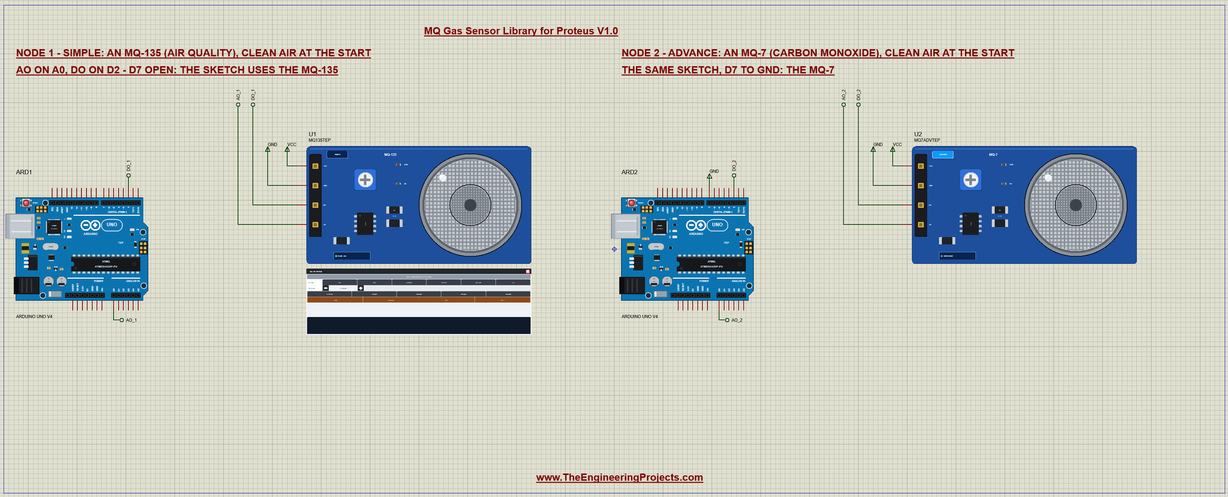
Wiring
| Module | Arduino UNO |
|---|---|
| VCC | 5V (the heater: about 150 mA) |
| GND | GND |
| DO | D2 (LOW = gas above the threshold) |
| AO | A0 (higher with more gas) |
| - | D7: open = MQ-135, to GND = MQ-7 (the demo) |
In Proteus, AO and DO reach their UNO through net labels - AO_1 and DO_1 for node 1, AO_2 and DO_2 for node 2 - and VCC and GND are power terminals. The serial monitor needs no wires at all, because it is built into the UNO V4.0.
The Arduino Code
The demo sketch uses MQUnifiedsensor. New to Arduino? Start with Arduino Tutorial for Beginners and Introduction to Arduino UNO. The pins, and the 20 seconds the sketch gives the heater:
#include <MQUnifiedsensor.h>const uint8_t AO_PIN = A0, DO_PIN = 2, TYPE_PIN = 7;
const unsigned long WARMUP_MS = 20000UL; // the heater's warm-up before R0 is calibratedThe eight sensors live in two small tables in flash: each gas with its a, b and an offset, each sensor with its clean-air ratio. The MQ-135's CO2 curve gives the CO2 above the outdoor level, so its offset is 400 ppm, as in the library's own example:
struct GasDef { char name[8]; float a, b, offset; };
struct TypeDef { char name[7]; float clean; uint8_t first, count; bool mgl; };
{"CO2", 110.47, -2.862, 400}, {"NH3", 102.2, -2.473, 0}, {"ALCOHOL", 77.255, -3.18, 0}, {"TOLUENE", 44.947, -3.445, 0},
{"ACETONE", 34.668, -3.369, 0}, {"CO", 605.18, -3.937, 0} // MQ-135 (CO2: + the outdoor 400 ppm)One MQUnifiedsensor object does the work. useGas() gives it the curve of the chosen gas:
MQUnifiedsensor MQ("Arduino UNO", 5, 10, AO_PIN, "MQ");void useGas(uint8_t k) { // the gas whose curve readSensor() uses
gasIndex = k;
memcpy_P(&gas, &GASES[type.first + k], sizeof gas);
MQ.setA(gas.a); MQ.setB(gas.b);
}In setup() the sketch picks the sensor from D7, sets the power law and tells the library that this board's RL is 1 kOhm (its default is 10):
  useType(digitalRead(TYPE_PIN) == LOW ? 4 : 7);   // D7 to GND: MQ-7, open: MQ-135
  MQ.setRegressionMethod(1);                       // ppm = a x ratio^b
  MQ.setRL(1);                                     // the board's RL: 1 kOhm
  MQ.init();
The Warm-up and R0
For the first 20 seconds the sketch only prints the raw reading. Then it calibrates R0 in clean air - the average of ten readings, each Rs divided by the clean-air ratio:
    if (t < WARMUP_MS) {
      Serial.print(F("warming up: ADC ")); Serial.print(analogRead(AO_PIN));
      Serial.print(F(" - ")); Serial.print((WARMUP_MS - t) / 1000); Serial.println(F(" s left"));
      nextLine += 2000;
      return;
    }
void calibrate() {
float r0 = 0;
for (uint8_t i = 0; i < 10; i++) {
MQ.update();
r0 += MQ.calibrate(type.clean);
}
r0 /= 10;
MQ.setR0(r0);
calibrated = true;
Serial.print(F("R0 = ")); Serial.print(r0, 3); Serial.print(F(" kOhm (Rs in clean air / ")); Serial.print(type.clean, 1); Serial.println(')');
}A Reading
Once a second update() reads A0 (two analogReads), readSensor() turns it into the gas, and the sketch prints it all with DO:
void reading() {
  MQ.update();
  const float c = MQ.readSensor() + gas.offset;      // the library's ppm (+ 400 for the MQ-135's CO2)
  const float v = MQ.getVoltage(false);             // the voltage update() measured (two analogReads)
  const int a = (int)(v * 1023 / 5 + 0.5);
Serial.println(digitalRead(DO_PIN) == LOW ? F(" DO LOW - gas alarm") : F(" DO HIGH"));The HEX file is in the package, so you do not need the Arduino IDE to run the demo. To change the sketch, install MQUnifiedsensor from the Library Manager and export the compiled binary, as in How to get the HEX file from Arduino. It needs 13,836 bytes of flash and 620 bytes of RAM.
The Serial Monitor: Warm-up and Calibration
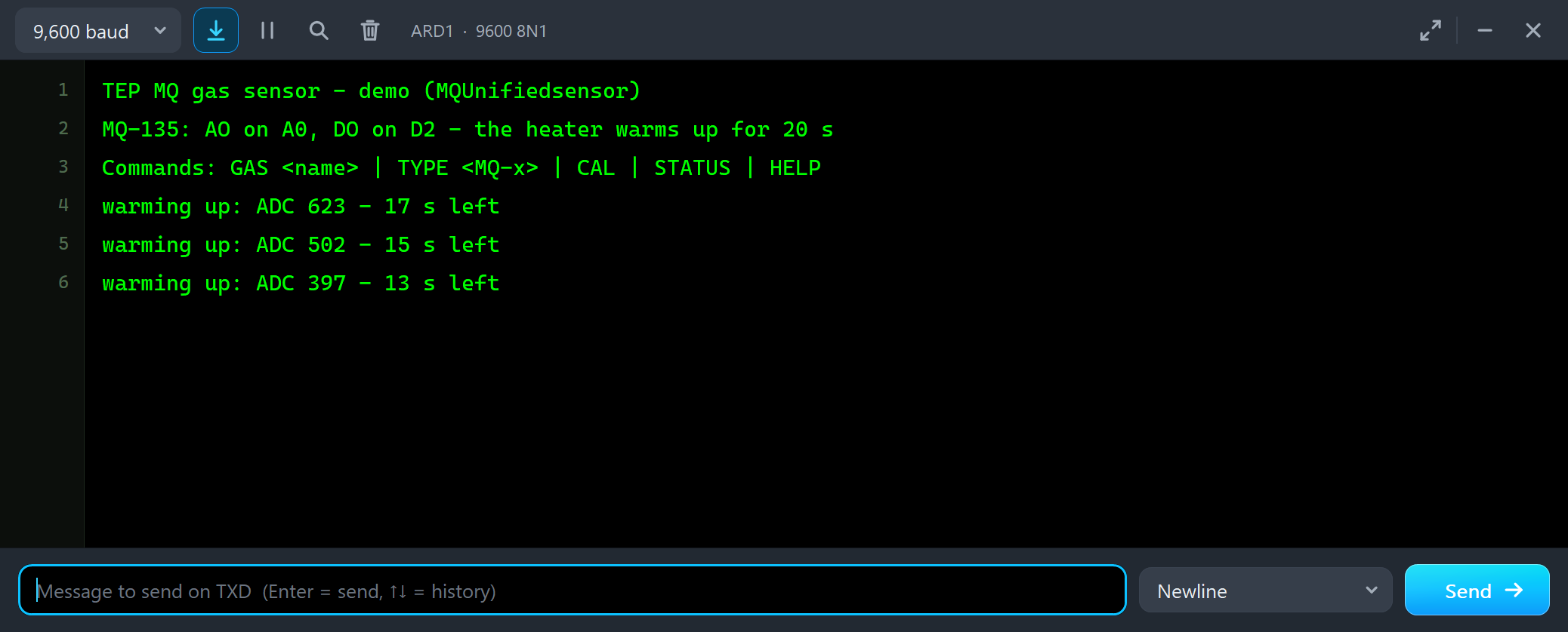
Both UNOs have the serial monitor built in, and it opens at Run. The screenshots use its Simple interface. Right after power-on, the heater is cold and Rs is far too low, so AO starts high:
TEP MQ gas sensor - demo (MQUnifiedsensor)
MQ-135: AO on A0, DO on D2 - the heater warms up for 20 s
Commands: GAS <name> | TYPE <MQ-x> | CAL | STATUS | HELP
warming up: ADC 623 - 17 s left
warming up: ADC 502 - 15 s left
warming up: ADC 397 - 13 s left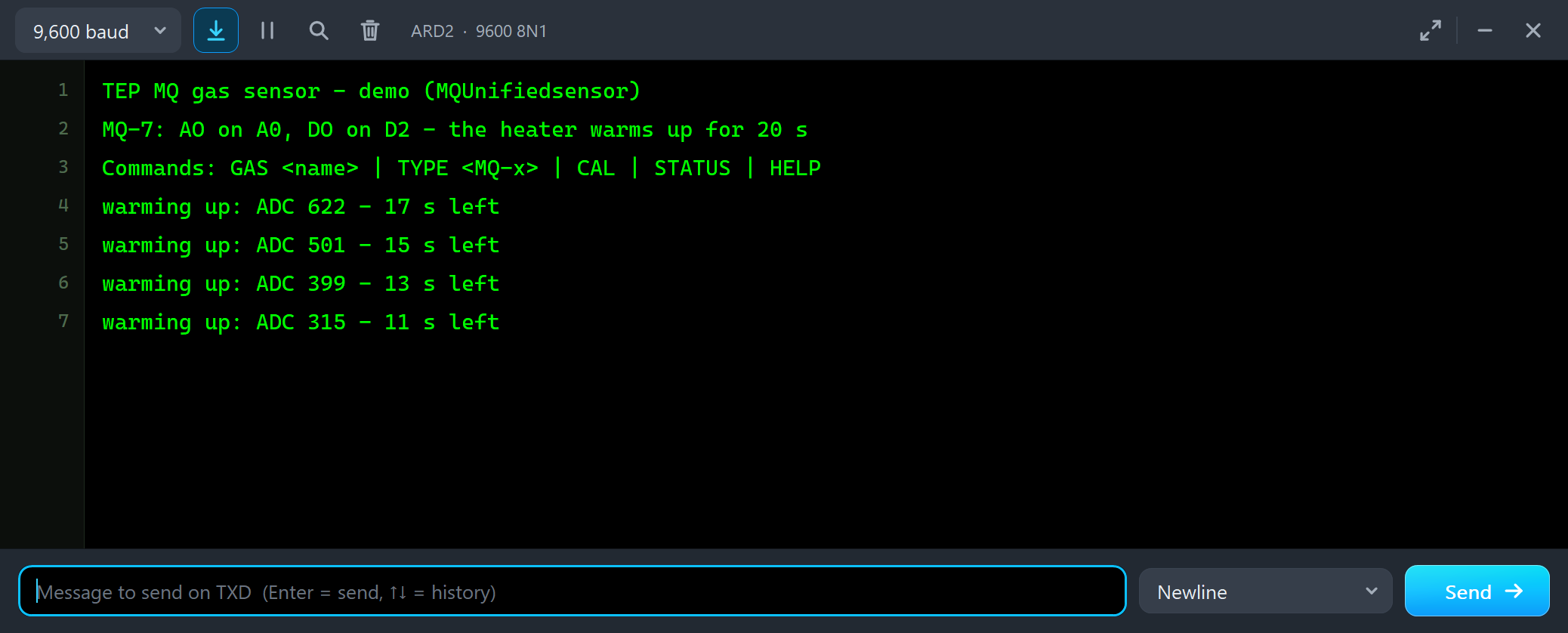
An analogRead of 623 would mean plenty of gas, but there is none: this is the warm-up. Both modules even showed a short false alarm - DO LOW for 0.65 s on the MQ-7 and 3.15 s on the MQ-135. Then the readings fall, and after 20 seconds the sketch calibrates:
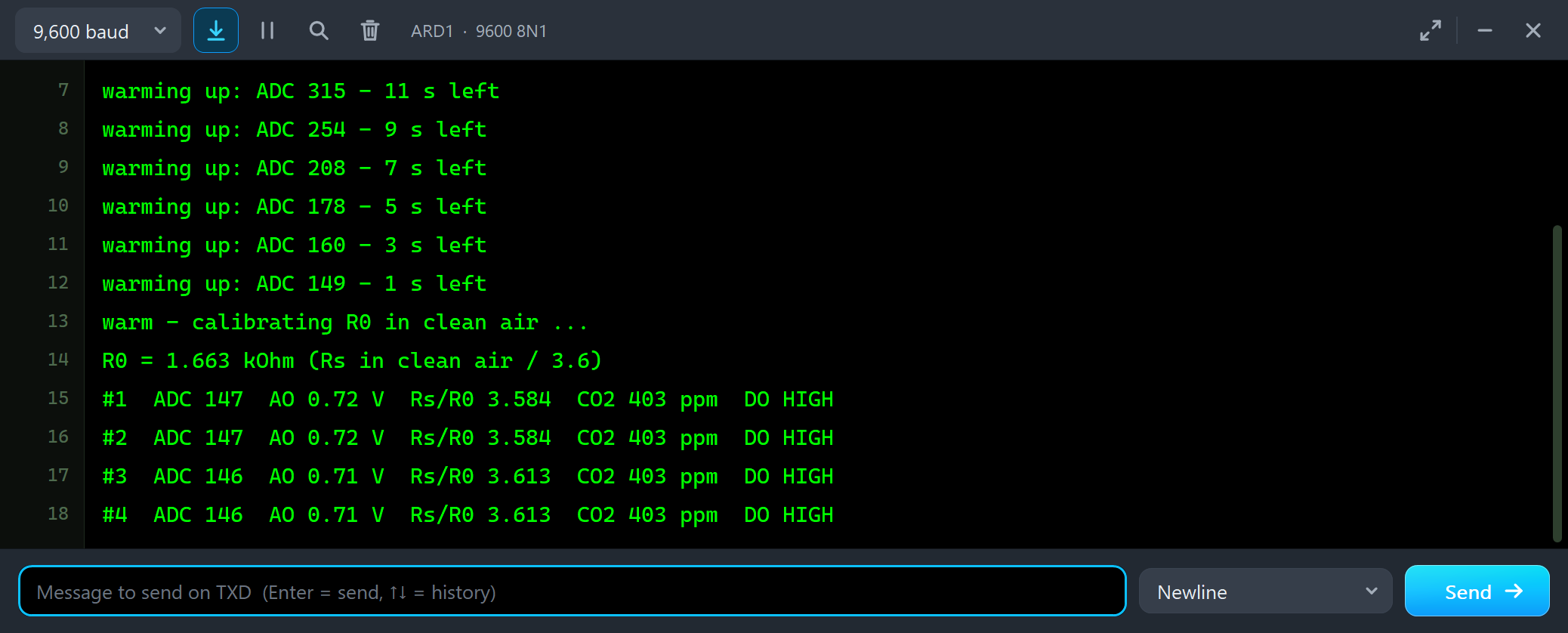
warming up: ADC 315 - 11 s left
warming up: ADC 254 - 9 s left
warming up: ADC 208 - 7 s left
warming up: ADC 178 - 5 s left
warming up: ADC 160 - 3 s left
warming up: ADC 149 - 1 s left
warm - calibrating R0 in clean air ...
R0 = 1.663 kOhm (Rs in clean air / 3.6)
#1  ADC 147  AO 0.72 V  Rs/R0 3.584  CO2 403 ppm  DO HIGH
#2  ADC 147  AO 0.72 V  Rs/R0 3.584  CO2 403 ppm  DO HIGH
#3  ADC 146  AO 0.71 V  Rs/R0 3.613  CO2 403 ppm  DO HIGH
In clean air the MQ-135 reads about 0.72 V - analogRead 146 or 147 - and R0 comes out at 1.663 kOhm. Clean air reads 403 ppm of CO2: the outdoor 400 ppm plus the 2.8 ppm the curve gives at the clean-air ratio. The MQ-7 does the same with its own ratio, 27.5:
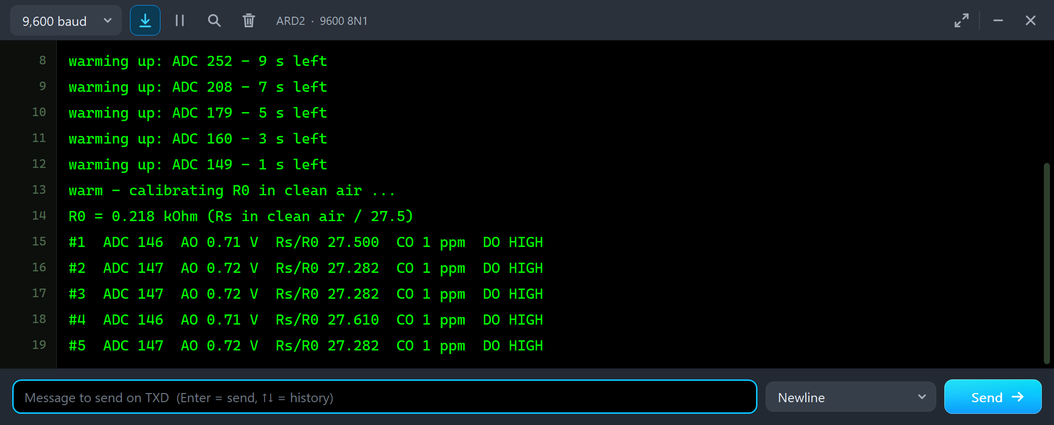
warm - calibrating R0 in clean air ...
R0 = 0.218 kOhm (Rs in clean air / 27.5)
#1  ADC 146  AO 0.71 V  Rs/R0 27.500  CO 1 ppm  DO HIGH
#2  ADC 147  AO 0.72 V  Rs/R0 27.282  CO 1 ppm  DO HIGH
#3  ADC 147  AO 0.72 V  Rs/R0 27.282  CO 1 ppm  DO HIGH
The Advance Pop-Up Window: an MQ-7
At Run, the MQ-7 opens its own window, MQ-7 Gas Sensor, with the look of our TEP Serial Monitor Advance for Proteus. It has three tabs, Sensor, Event log and Tests, plus Settings and Help behind the gear and question mark icons. The status bar at the bottom always shows the gas, AO and DO.
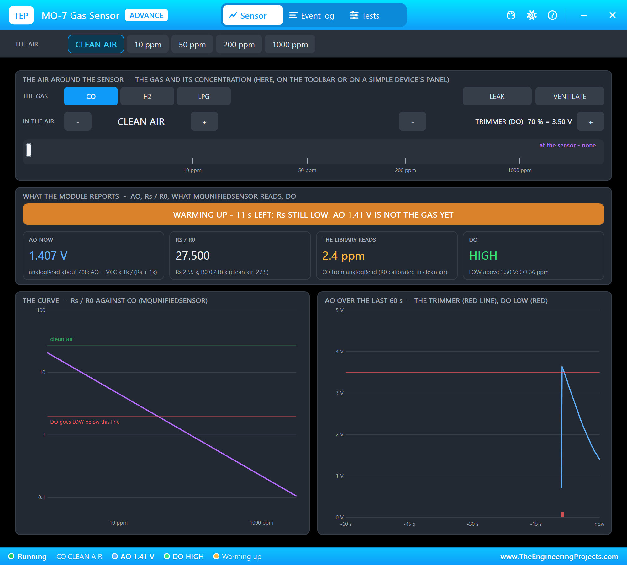
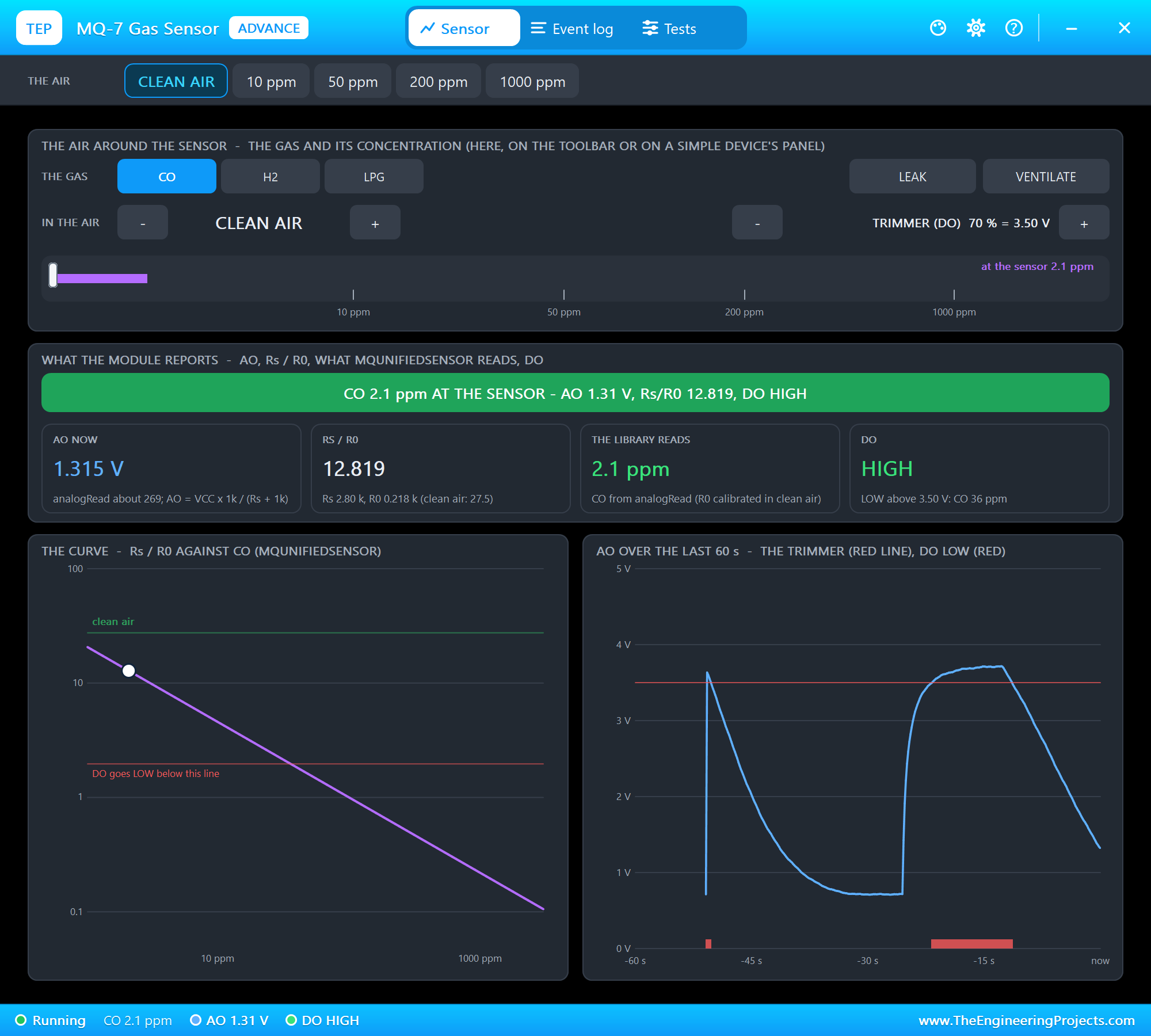
The toolbar carries the presets. The air around the sensor has the gases, - and +, LEAK, VENTILATE and the trimmer, and a log bar with the gas in the air and the gas at the sensor. What the module reports shows the banner, AO, Rs/R0, what MQUnifiedsensor reads from analogRead, and DO with its threshold. The curve plots Rs/R0 against the gas, with the clean-air line, DO's line and the sensor's point; AO over the last 60 s shows the trimmer's voltage and DO LOW in red. After the warm-up:
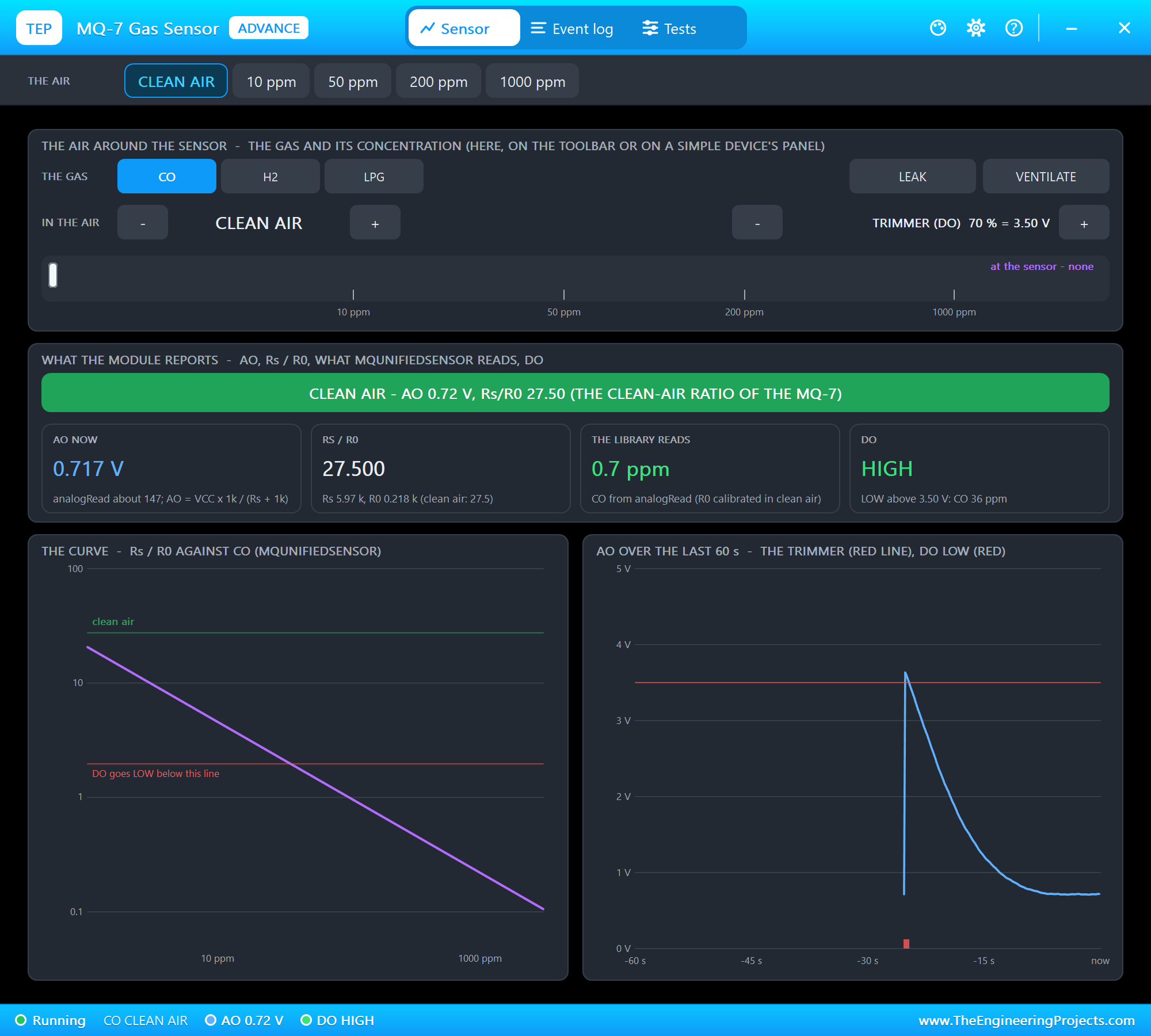
CO 50 ppm: the Alarm
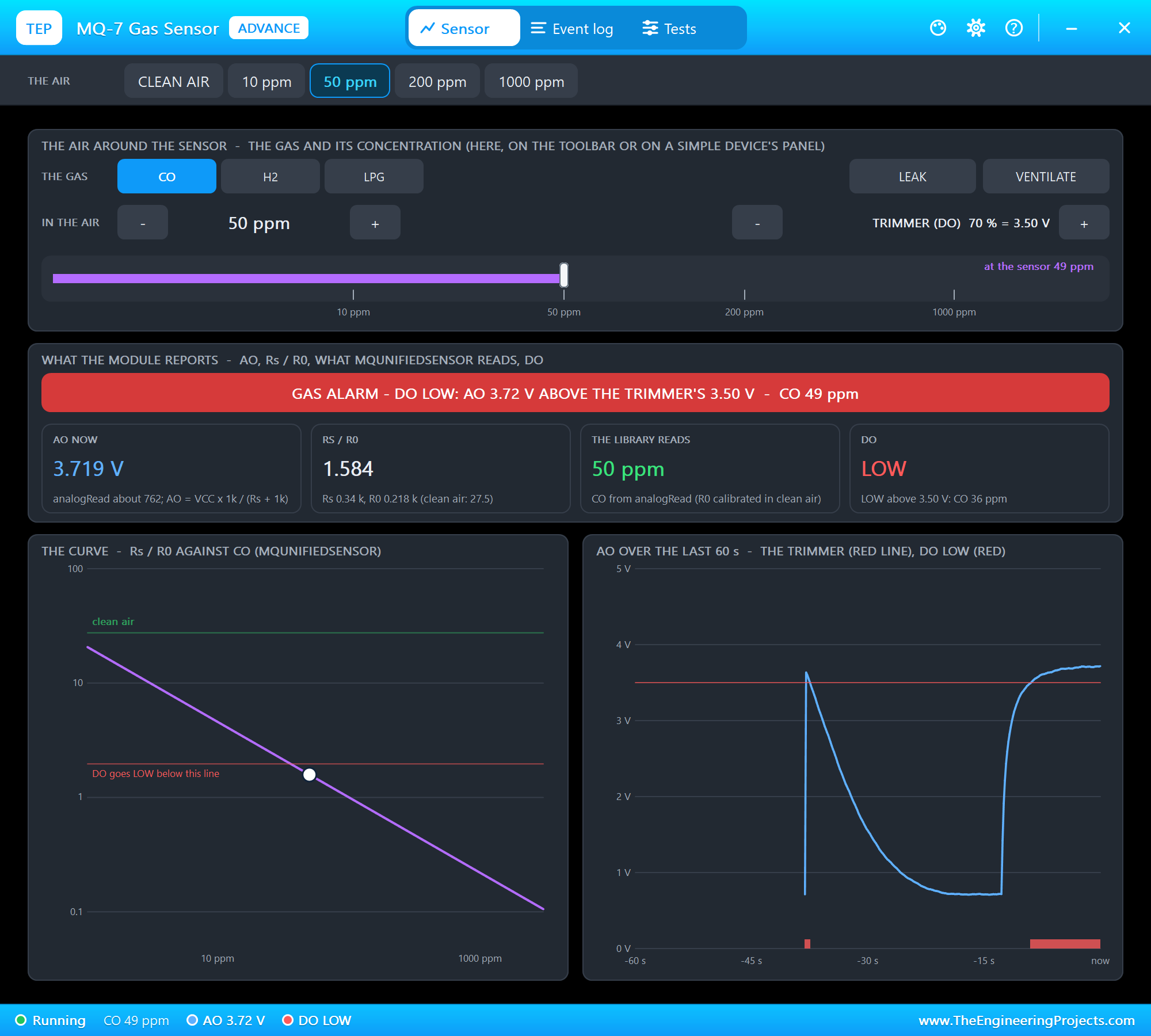
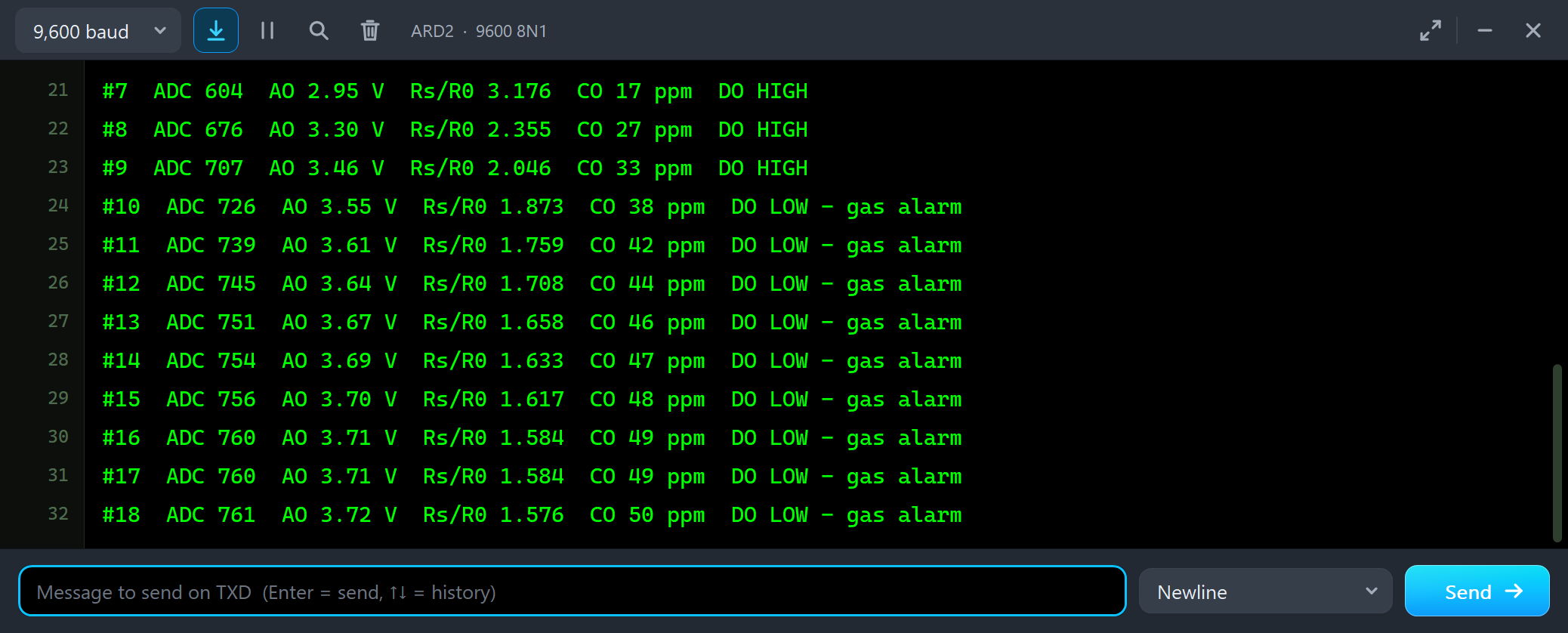
We clicked 50 ppm on the toolbar:
#7  ADC 604  AO 2.95 V  Rs/R0 3.176  CO 17 ppm  DO HIGH
#8  ADC 676  AO 3.30 V  Rs/R0 2.355  CO 27 ppm  DO HIGH
#9  ADC 707  AO 3.46 V  Rs/R0 2.046  CO 33 ppm  DO HIGH
#10  ADC 726  AO 3.55 V  Rs/R0 1.873  CO 38 ppm  DO LOW - gas alarm
#11  ADC 739  AO 3.61 V  Rs/R0 1.759  CO 42 ppm  DO LOW - gas alarm
#12  ADC 745  AO 3.64 V  Rs/R0 1.708  CO 44 ppm  DO LOW - gas alarm
#16  ADC 760  AO 3.71 V  Rs/R0 1.584  CO 49 ppm  DO LOW - gas alarm
#17  ADC 760  AO 3.71 V  Rs/R0 1.584  CO 49 ppm  DO LOW - gas alarm
#18  ADC 761  AO 3.72 V  Rs/R0 1.576  CO 50 ppm  DO LOW - gas alarm
The gas does not reach the sensor at once: the reading climbs 17, 27, 33 ppm and settles at 50 ppm after about ten seconds - the library reads back exactly what we set. On the way AO passes the trimmer's 3.50 V near 36 ppm, and DO goes LOW: the alarm. The Event log says when: DO LOW at 29.158 s, the CO at the sensor at 50 ppm at 37.088 s.
VENTILATE
#20  ADC 712  AO 3.48 V  Rs/R0 2.004  CO 34 ppm  DO HIGH
#21  ADC 676  AO 3.30 V  Rs/R0 2.355  CO 27 ppm  DO HIGH
#22  ADC 638  AO 3.12 V  Rs/R0 2.768  CO 21 ppm  DO HIGH
#23  ADC 596  AO 2.91 V  Rs/R0 3.287  CO 16 ppm  DO HIGH
#24  ADC 557  AO 2.72 V  Rs/R0 3.838  CO 13 ppm  DO HIGH
#25  ADC 515  AO 2.51 V  Rs/R0 4.525  CO 10 ppm  DO HIGH
#26  ADC 472  AO 2.30 V  Rs/R0 5.355  CO 8 ppm  DO HIGH
#28  ADC 389  AO 1.90 V  Rs/R0 7.477  CO 5 ppm  DO HIGH
#30  ADC 314  AO 1.53 V  Rs/R0 10.361  CO 3 ppm  DO HIGH
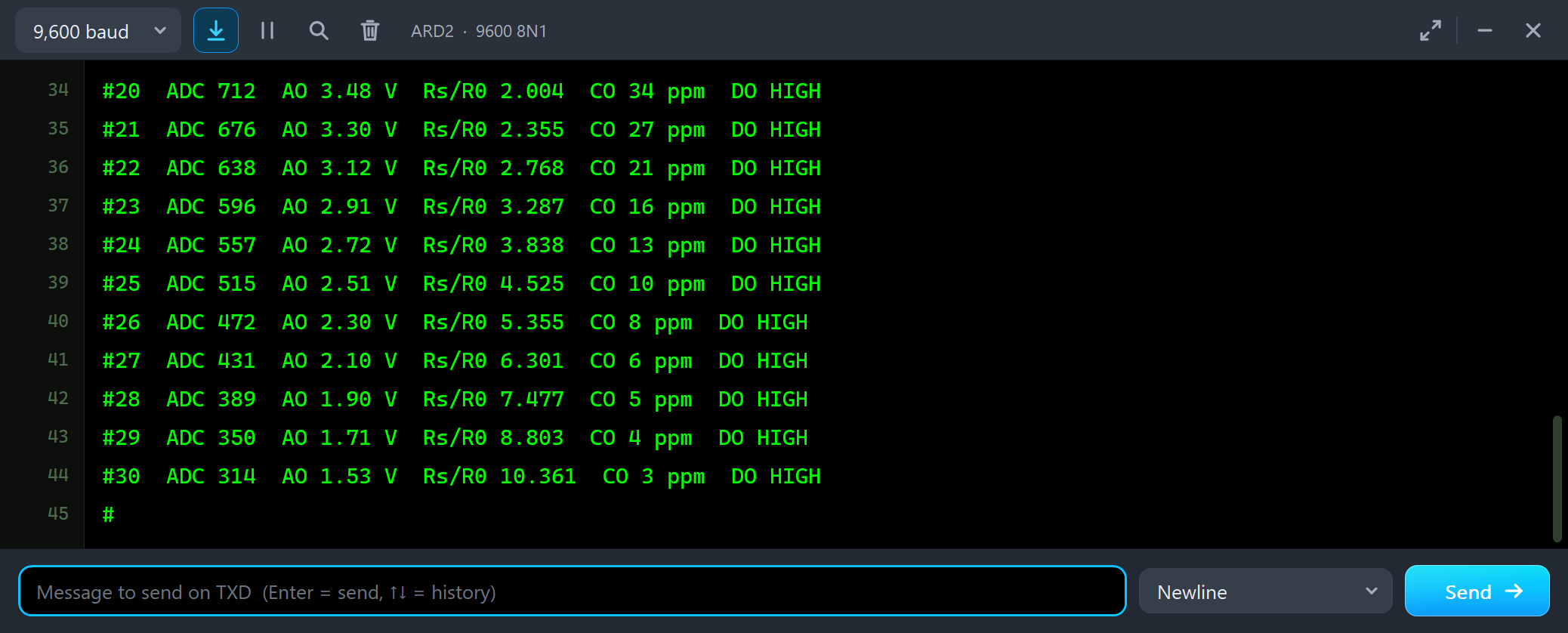
VENTILATE brings fresh air in: the reading falls from 50 to 3 ppm in about 12 seconds, and DO goes HIGH again as AO drops below the trimmer.
H2: the Wrong Gas
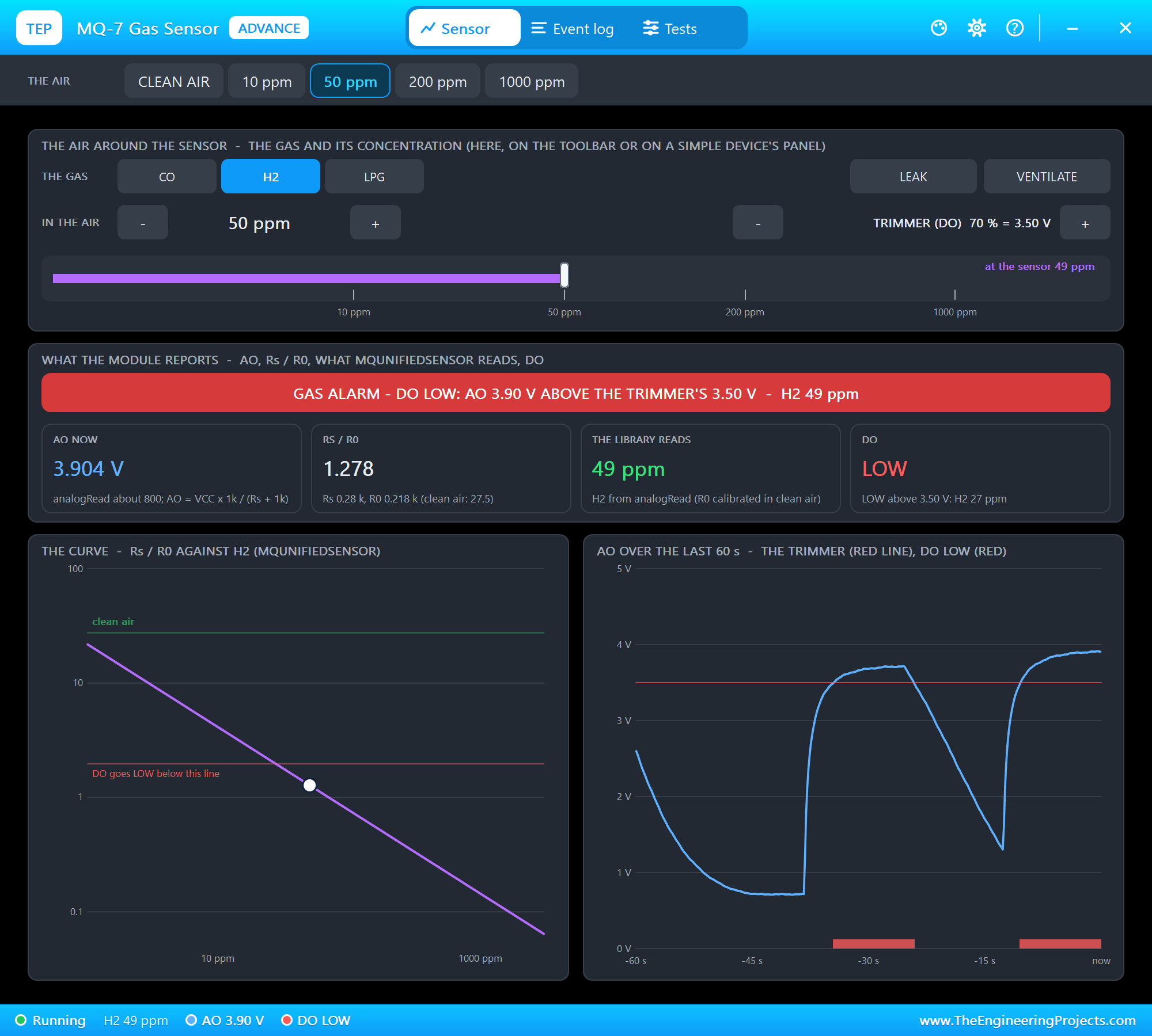
Now the interesting part. We chose H2 and clicked 50 ppm - hydrogen, not CO. The sketch still uses the CO curve:
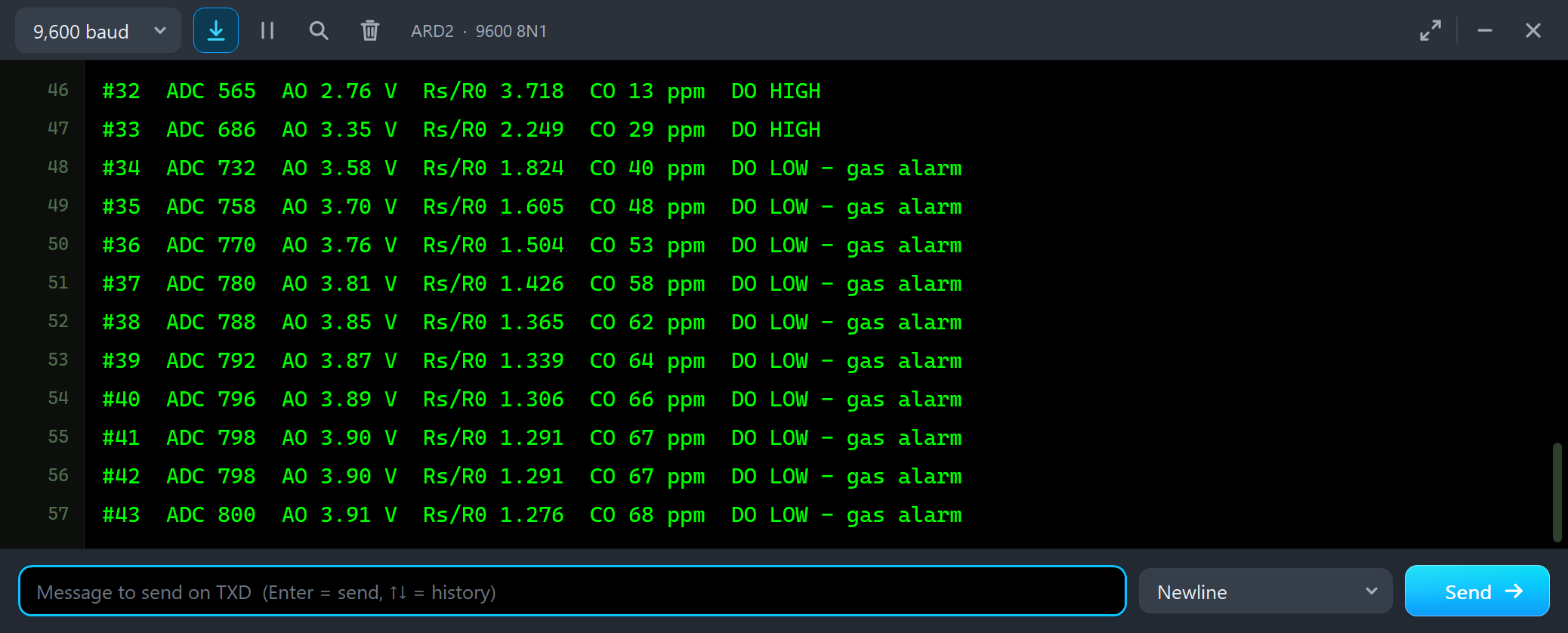
#32  ADC 565  AO 2.76 V  Rs/R0 3.718  CO 13 ppm  DO HIGH
#33  ADC 686  AO 3.35 V  Rs/R0 2.249  CO 23 ppm  DO HIGH
#34  ADC 732  AO 3.58 V  Rs/R0 1.824  CO 40 ppm  DO LOW - gas alarm
#35  ADC 758  AO 3.70 V  Rs/R0 1.605  CO 48 ppm  DO LOW - gas alarm
#36  ADC 770  AO 3.76 V  Rs/R0 1.504  CO 53 ppm  DO LOW - gas alarm
#38  ADC 788  AO 3.85 V  Rs/R0 1.365  CO 62 ppm  DO LOW - gas alarm
#40  ADC 796  AO 3.89 V  Rs/R0 1.306  CO 66 ppm  DO LOW - gas alarm
#43  ADC 800  AO 3.91 V  Rs/R0 1.276  CO 68 ppm  DO LOW - gas alarm
Fifty ppm of hydrogen reads as 68 ppm of CO - more than the 50 ppm of real CO before - and the alarm goes off. The MQ-7 cannot tell the two gases apart: it only knows that its resistance fell. Then we typed GAS H2:
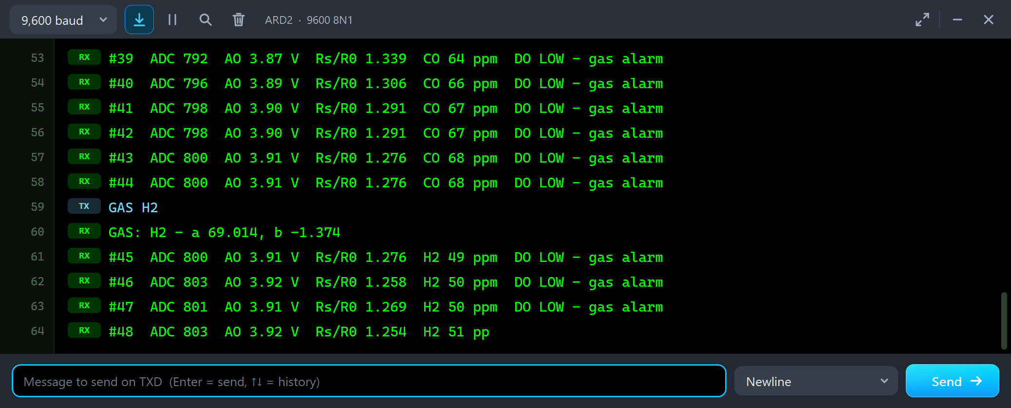
#44  ADC 800  AO 3.91 V  Rs/R0 1.276  CO 68 ppm  DO LOW - gas alarm
GAS H2
GAS: H2 - a 69.014, b -1.374
#45  ADC 800  AO 3.91 V  Rs/R0 1.276  H2 49 ppm  DO LOW - gas alarm
#46  ADC 803  AO 3.92 V  Rs/R0 1.258  H2 50 ppm  DO LOW - gas alarm
#47  ADC 801  AO 3.91 V  Rs/R0 1.269  H2 50 ppm  DO LOW - gas alarm
The same analogRead of 800 now reads H2 50 ppm. The curve you choose decides the number; the sensor alone cannot. In a kitchen or a garage, know which gases can be there before you trust a reading.
The Test Tools
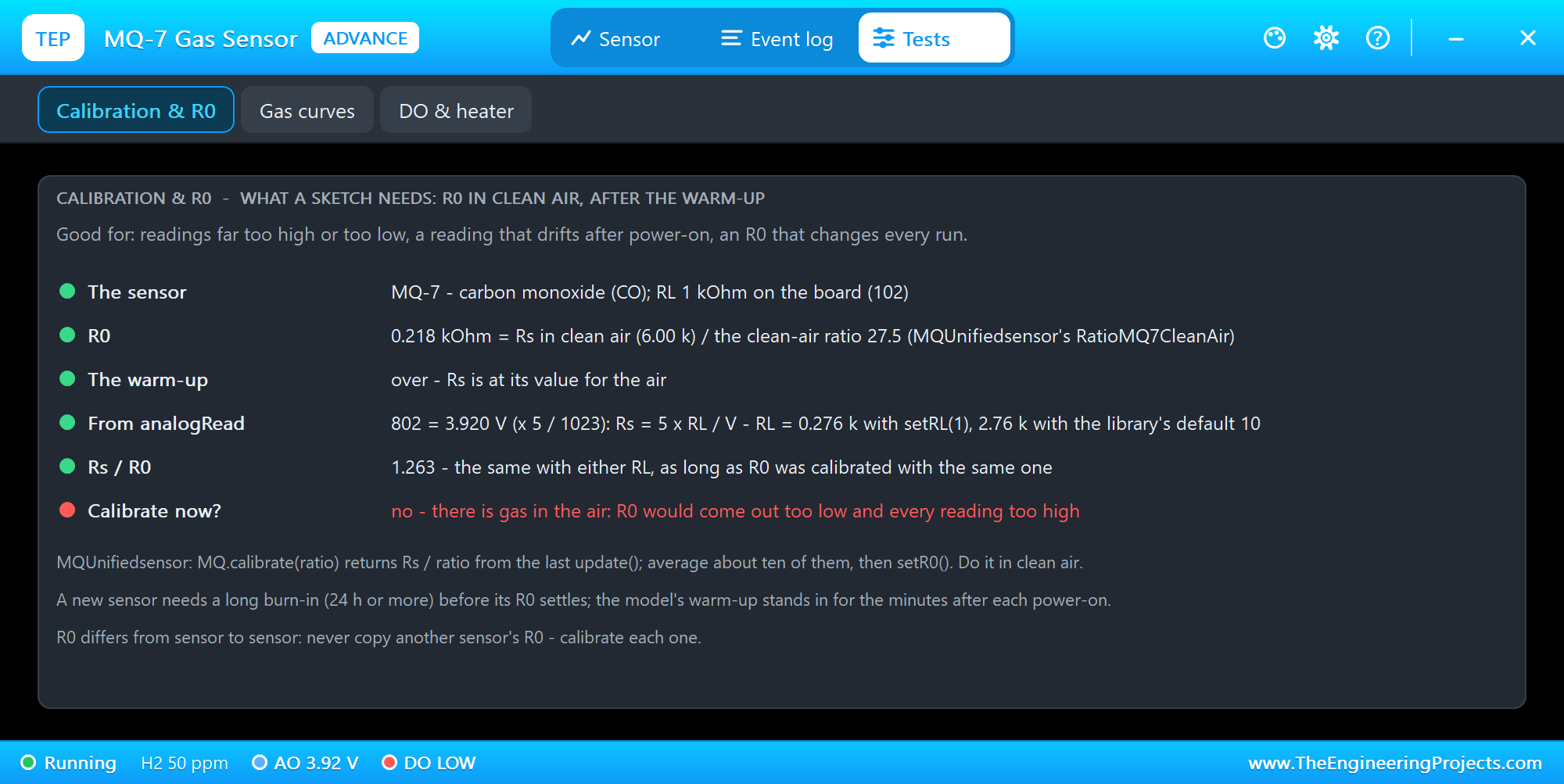
The Calibration & R0 tool is the one to open when every reading is too high or too low. It shows how R0 comes about (Rs in clean air divided by the clean-air ratio), the warm-up - and how wrong an R0 calibrated during it would be - what MQUnifiedsensor computes from the current analogRead with setRL(1) and with its default of 10, and whether to calibrate now: here no, because there is gas in the air.
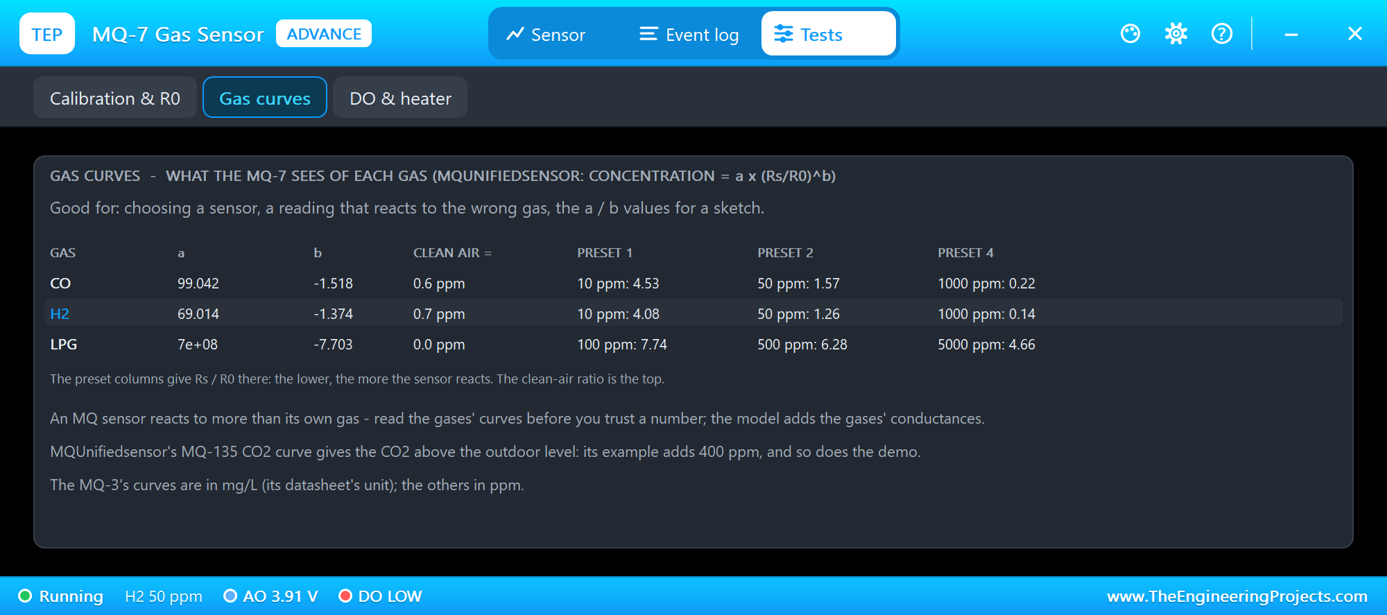
The Gas curves tool lists every gas of the sensor with its a and b, what clean air reads as, and Rs/R0 at its presets - the lower the ratio, the stronger the reaction. On the MQ-7, hydrogen pulls Rs down more than CO, and LPG hardly at all.
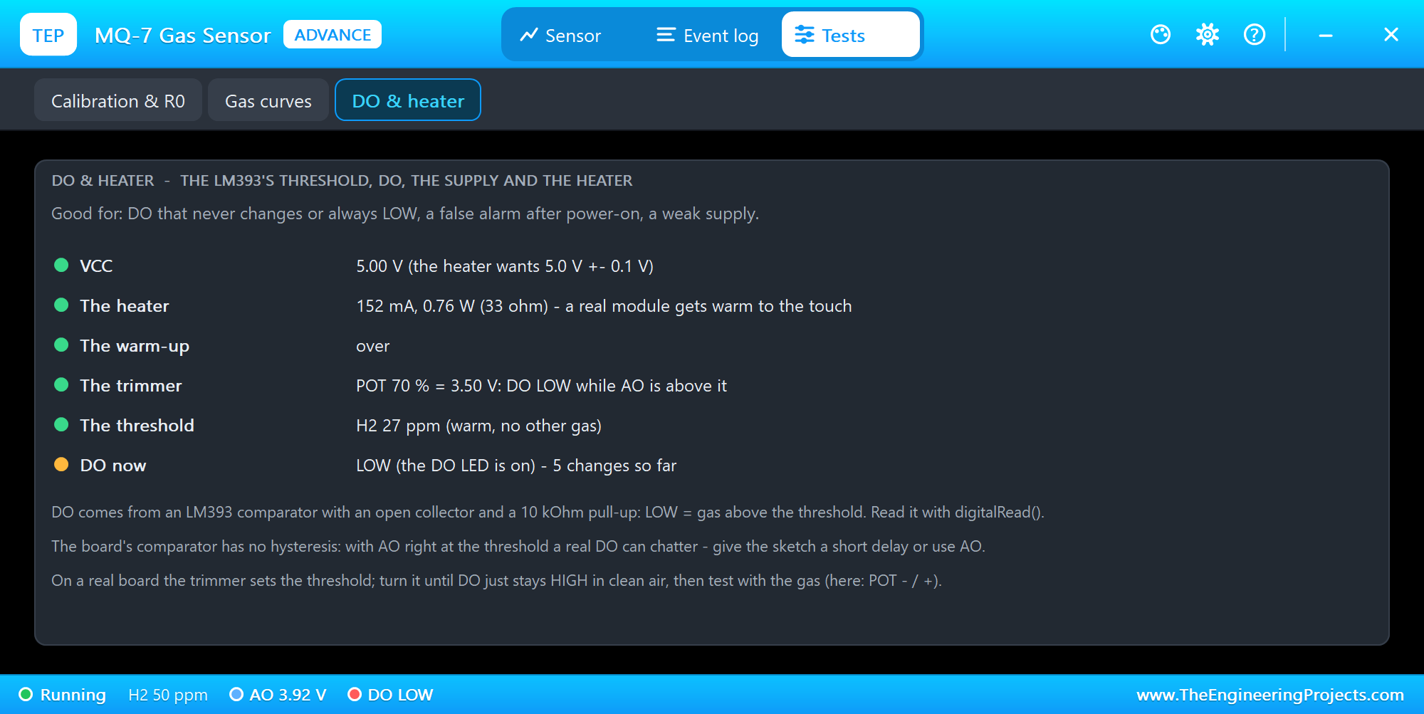
The DO & heater tool shows VCC, the heater's 152 mA and 0.76 W, the warm-up, the trimmer and the threshold in the gas's units, and DO with its changes.
The Event Log
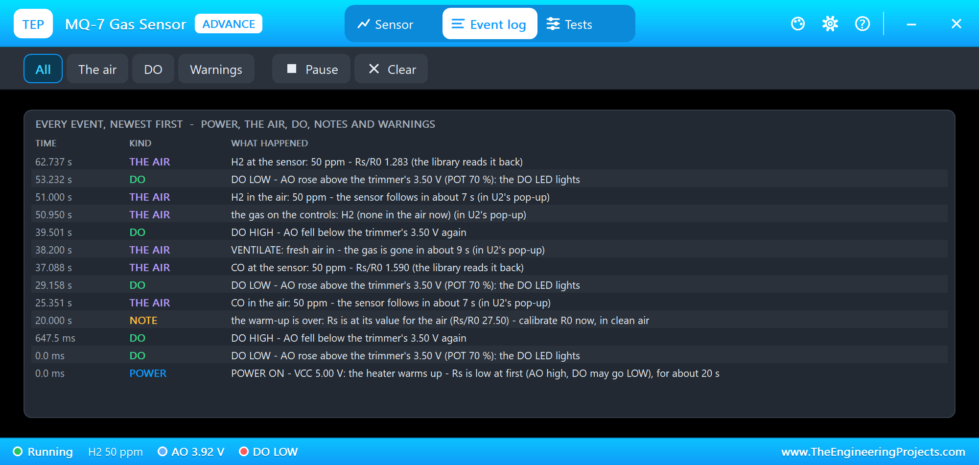
The Event log lists everything that happened, newest first: power, the air (the gas and when it reaches the sensor), DO, notes and warnings. Filter it by the air, DO or warnings, pause it, or clear it.
An MQ-135 on the STATUS Panel
Now node 1, the MQ-135. We clicked the buttons of U1's STATUS panel with the mouse while the simulation ran. First 1000 ppm of CO2:
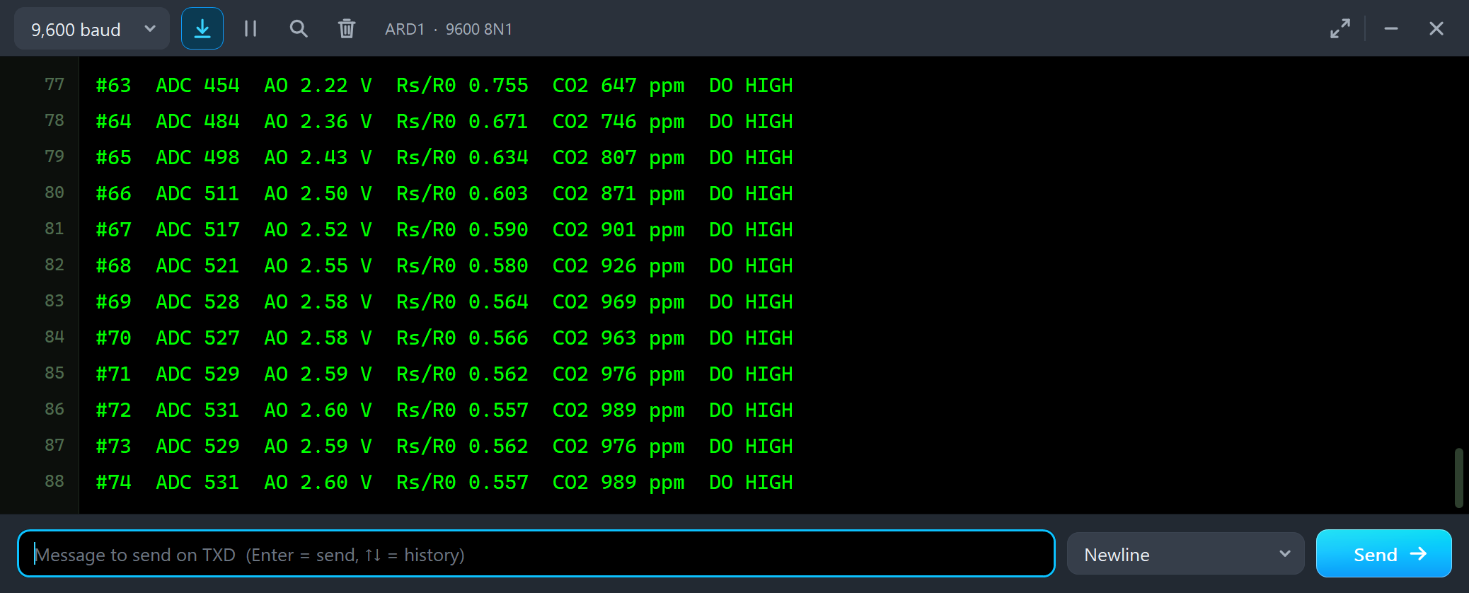
#63  ADC 454  AO 2.22 V  Rs/R0 0.755  CO2 647 ppm  DO HIGH
#64  ADC 484  AO 2.36 V  Rs/R0 0.671  CO2 746 ppm  DO HIGH
#65  ADC 498  AO 2.43 V  Rs/R0 0.634  CO2 807 ppm  DO HIGH
#66  ADC 511  AO 2.50 V  Rs/R0 0.603  CO2 871 ppm  DO HIGH
#67  ADC 517  AO 2.52 V  Rs/R0 0.590  CO2 901 ppm  DO HIGH
#69  ADC 528  AO 2.58 V  Rs/R0 0.564  CO2 969 ppm  DO HIGH
#72  ADC 531  AO 2.60 V  Rs/R0 0.557  CO2 989 ppm  DO HIGH
#73  ADC 529  AO 2.59 V  Rs/R0 0.562  CO2 976 ppm  DO HIGH
#74  ADC 531  AO 2.60 V  Rs/R0 0.557  CO2 989 ppm  DO HIGH
A room with 1000 ppm of CO2 is a room that needs air. The reading climbs from 647 to 989 ppm within ten lines - still below the trimmer, so DO stays HIGH. Then LEAK:
LEAK: the Alarm
#79  ADC 589  AO 2.88 V  Rs/R0 0.443  CO2 1534 ppm  DO LOW - gas alarm
#80  ADC 595  AO 2.91 V  Rs/R0 0.433  CO2 1615 ppm  DO LOW - gas alarm
#82  ADC 602  AO 2.94 V  Rs/R0 0.421  CO2 1717 ppm  DO LOW - gas alarm
#84  ADC 606  AO 2.96 V  Rs/R0 0.414  CO2 1780 ppm  DO LOW - gas alarm
#85  ADC 611  AO 2.99 V  Rs/R0 0.406  CO2 1862 ppm  DO LOW - gas alarm
#88  ADC 613  AO 3.00 V  Rs/R0 0.402  CO2 1896 ppm  DO LOW - gas alarm
#89  ADC 612  AO 2.99 V  Rs/R0 0.404  CO2 1879 ppm  DO LOW - gas alarm
#90  ADC 615  AO 3.00 V  Rs/R0 0.400  CO2 1923 ppm  DO LOW - gas alarm
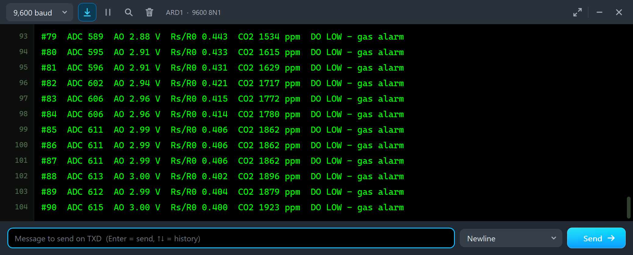
LEAK lets the gas spread in up to the third preset, 2000 ppm. Past about 1250 ppm, AO rises above the trimmer's 2.75 V and DO goes LOW - GAS ALARM on the panel, the DO LED on the board. Then VENTILATE:
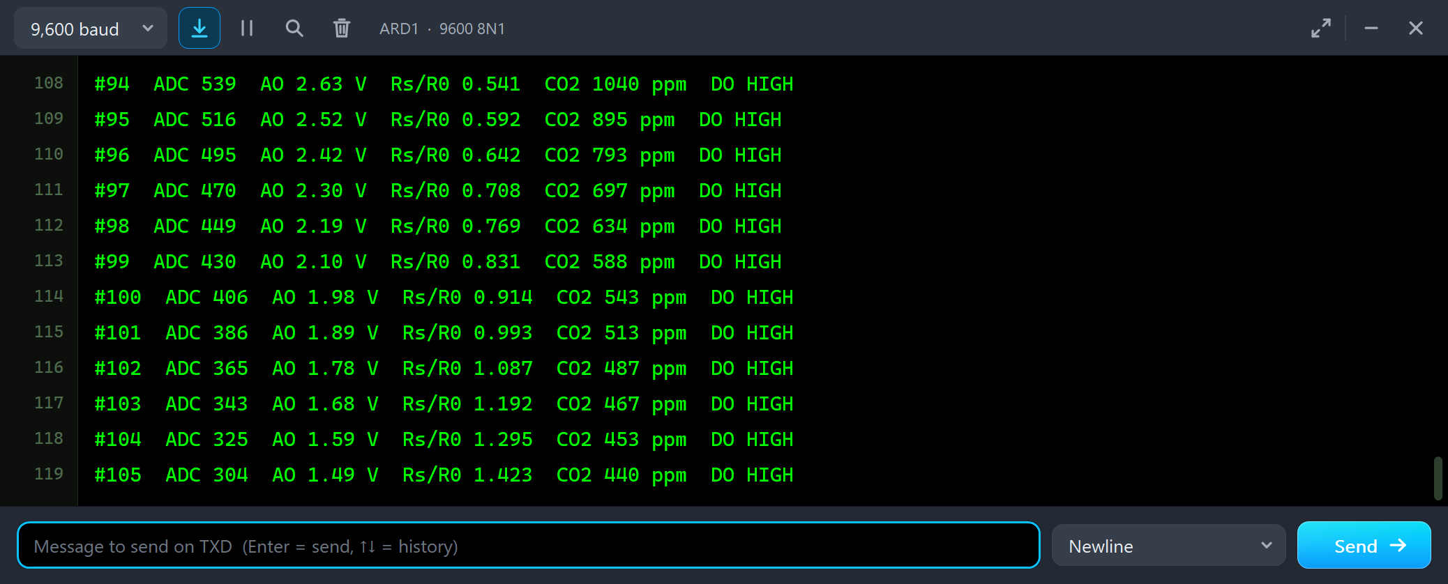
#94  ADC 539  AO 2.63 V  Rs/R0 0.541  CO2 1040 ppm  DO HIGH
#95  ADC 516  AO 2.52 V  Rs/R0 0.592  CO2 895 ppm  DO HIGH
#96  ADC 495  AO 2.42 V  Rs/R0 0.642  CO2 793 ppm  DO HIGH
#97  ADC 470  AO 2.30 V  Rs/R0 0.708  CO2 697 ppm  DO HIGH
#98  ADC 449  AO 2.19 V  Rs/R0 0.769  CO2 634 ppm  DO HIGH
#100  ADC 406  AO 1.98 V  Rs/R0 0.914  CO2 543 ppm  DO HIGH
#102  ADC 365  AO 1.78 V  Rs/R0 1.087  CO2 487 ppm  DO HIGH
#104  ADC 325  AO 1.59 V  Rs/R0 1.295  CO2 453 ppm  DO HIGH
#105  ADC 304  AO 1.49 V  Rs/R0 1.423  CO2 440 ppm  DO HIGH
The CO2 falls back towards the outdoor 400 ppm, quickly at first and then more slowly - the last few ppm take the longest.
NH3: Another Wrong Gas
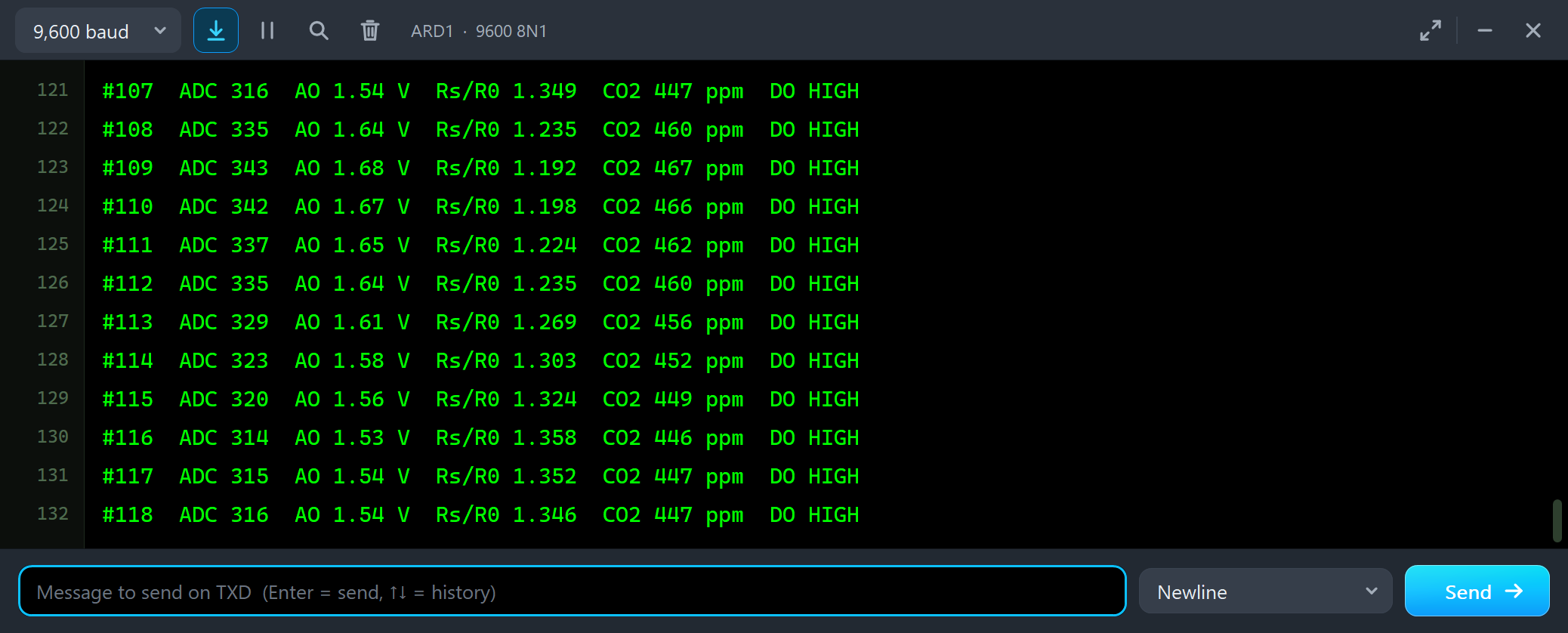
#107  ADC 316  AO 1.54 V  Rs/R0 1.349  CO2 447 ppm  DO HIGH
#108  ADC 335  AO 1.64 V  Rs/R0 1.235  CO2 460 ppm  DO HIGH
#109  ADC 343  AO 1.68 V  Rs/R0 1.192  CO2 467 ppm  DO HIGH
#111  ADC 337  AO 1.65 V  Rs/R0 1.224  CO2 462 ppm  DO HIGH
#114  ADC 323  AO 1.58 V  Rs/R0 1.303  CO2 452 ppm  DO HIGH
#116  ADC 314  AO 1.53 V  Rs/R0 1.358  CO2 446 ppm  DO HIGH
#117  ADC 315  AO 1.54 V  Rs/R0 1.352  CO2 447 ppm  DO HIGH
#118  ADC 316  AO 1.54 V  Rs/R0 1.346  CO2 447 ppm  DO HIGH
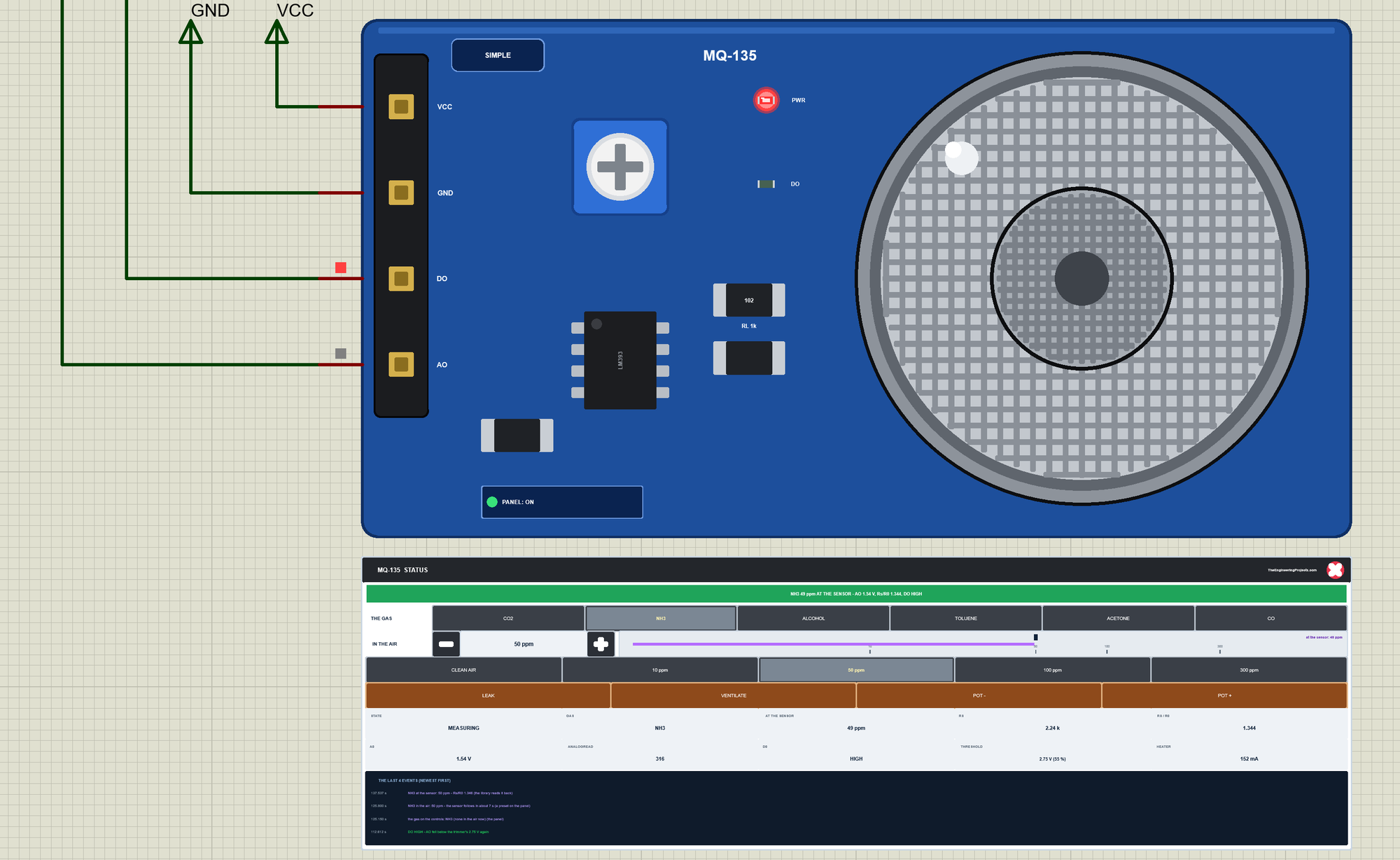
We chose NH3 and clicked 50 ppm. The sketch, still on the CO2 curve, settles at 447 ppm of CO2; for a few seconds the reading even rose to 467 ppm while the last of the CO2 was still leaving. An air-quality meter cannot say whether the air is bad because of people or because of ammonia. Then GAS NH3 and STATUS:
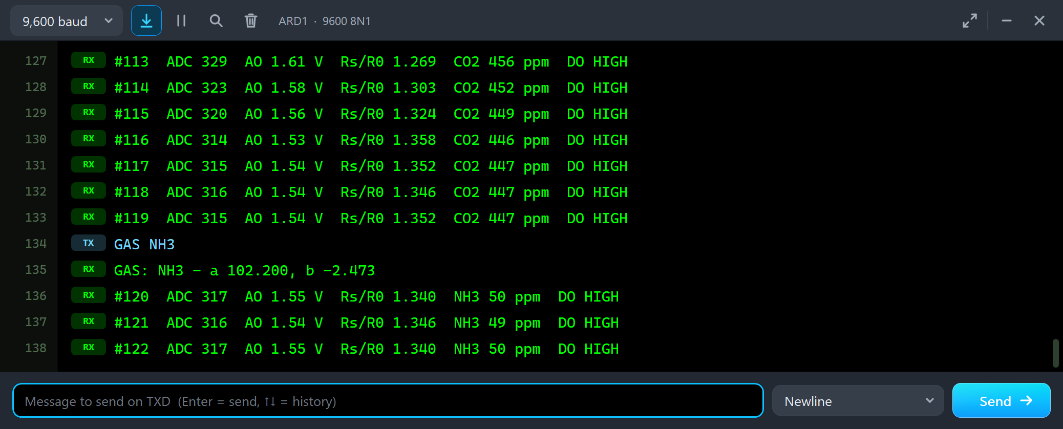
#119  ADC 315  AO 1.54 V  Rs/R0 1.352  CO2 447 ppm  DO HIGH
GAS NH3
GAS: NH3 - a 102.200, b -2.473
#120  ADC 317  AO 1.55 V  Rs/R0 1.340  NH3 50 ppm  DO HIGH
#121  ADC 316  AO 1.54 V  Rs/R0 1.346  NH3 49 ppm  DO HIGH
#122  ADC 317  AO 1.55 V  Rs/R0 1.340  NH3 50 ppm  DO HIGH
#123  ADC 319  AO 1.56 V  Rs/R0 1.327  NH3 51 ppm  DO HIGH
STATUS
STATUS: MQ-135, NH3 (a 102.200, b -2.473), R0 1.663 kOhm, RL 1 kOhm, warm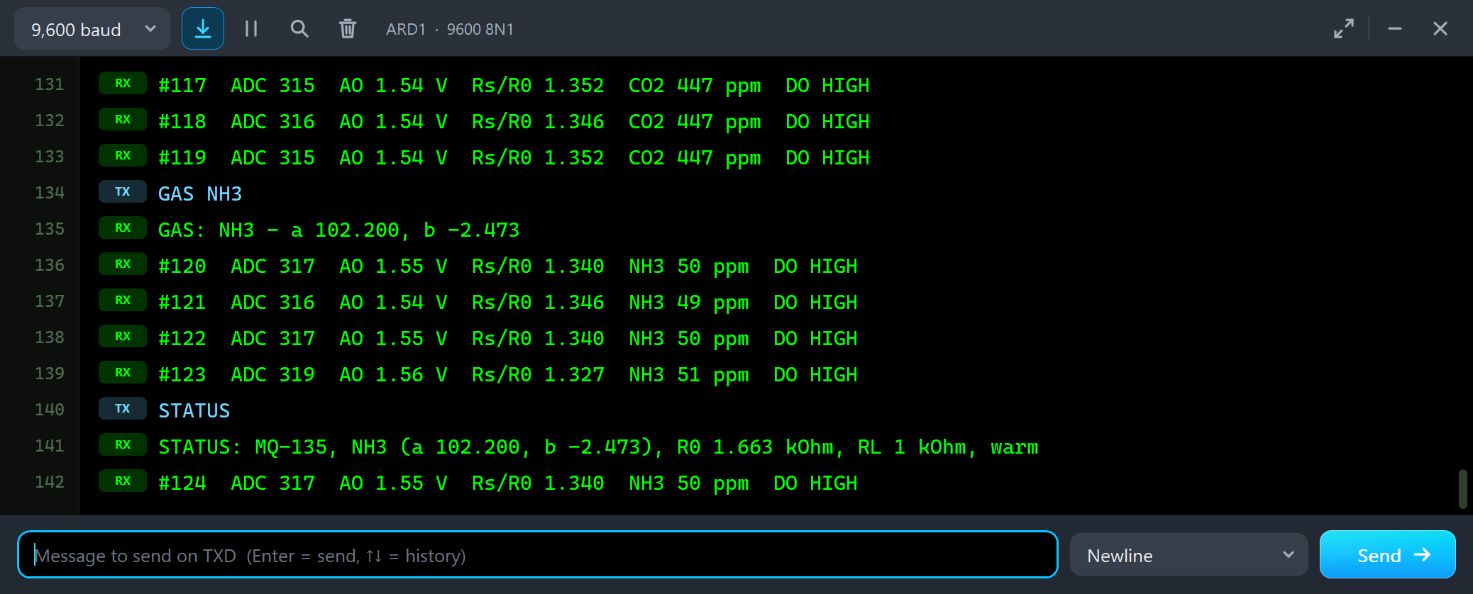
With the NH3 curve the same analogRead reads 50 ppm. STATUS shows the curve in use (a 102.2, b -2.473 - MQUnifiedsensor calls this gas NH4), R0, RL and that the heater is warm.
The Simulation Log
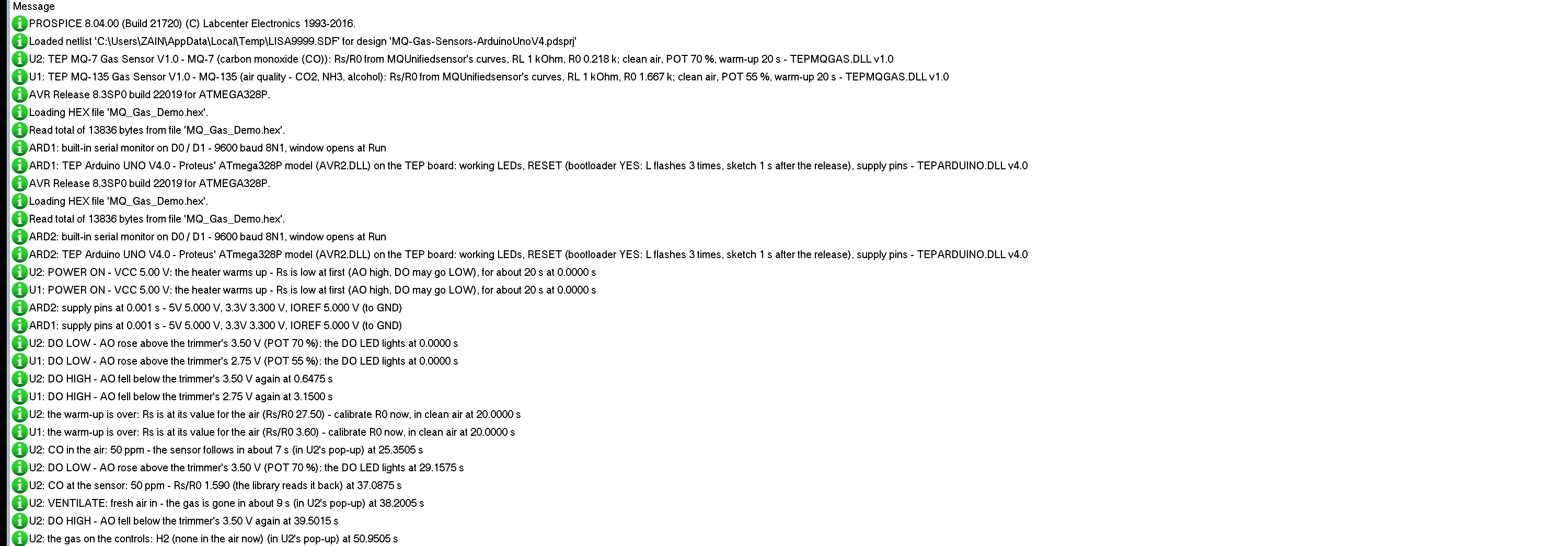
The modules also write to the simulation log of Proteus, with the exact simulation time. This part shows the MQ-7:
U2: POWER ON - VCC 5.00 V: the heater warms up - Rs is low at first (AO high, DO may go LOW), for about 20 s at 0.0000 s
U2: DO LOW - AO rose above the trimmer's 3.50 V (POT 70 %): the DO LED lights at 0.0000 s
U2: DO HIGH - AO fell below the trimmer's 3.50 V again at 0.6475 s
U2: the warm-up is over: Rs is at its value for the air (Rs/R0 27.50) - calibrate R0 now, in clean air at 20.0000 s
U2: CO in the air: 50 ppm - the sensor follows in about 7 s (in U2's pop-up) at 25.3505 s
U2: DO LOW - AO rose above the trimmer's 3.50 V (POT 70 %): the DO LED lights at 29.1575 s
U2: CO at the sensor: 50 ppm - Rs/R0 1.590 (the library reads it back) at 37.0875 s
The false alarm at power-on lasted 0.65 s; the warm-up ended at 20 s; the 50 ppm of CO clicked at 25.35 s raised the alarm at 29.16 s and reached the sensor in full at 37.09 s. Proteus logs the first 60 s; the Event log has the rest.
How the Model Works
The module is an analog model. VCC and GND feed the heater, a 33 ohm load. The sensor's Rs sits between VCC and AO, and the board's 1 kOhm RL between AO and GND, so Proteus itself solves AO. Rs is R0 times Rs/R0 from MQUnifiedsensor's curves, for the gas at the sensor, times the warm-up and a small noise. DO has its 10 kOhm pull-up and a switch to GND that closes while AO is above VCC times the trimmer. Proteus asks the model for Rs at every time step; the model answers from simple formulas, so it costs little time.
Troubleshooting
- The reading is far too high right after Run: the warm-up - wait, then calibrate (the demo waits 20 s).
- Every reading is too high or too low: R0 was calibrated with gas in the air, or during the warm-up - type CAL in clean air.
- The reading reacts to the wrong gas: an MQ sensor sees more than its main gas - the Gas curves tool shows how much; choose the curve with GAS.
- DO is LOW all the time: the trimmer is too low (POT +), or the module is still warming up. DO flickers: AO is right at the threshold.
- No part or no monitor: TEPMQGAS.DLL or TEPARDUINO.DLL is missing from MODELS and the project folder; a closed monitor opens again with a click on the UNO's USB port.
Things to Know Before Using a Real MQ Sensor
- Power: the heater draws about 150 mA and gets hot - give it a proper 5 V supply and let it warm up; a new sensor needs a burn-in of 24 hours or more.
- Calibrate each sensor: R0 differs from sensor to sensor, and temperature and humidity change Rs too.
- MQ-7 and MQ-9: their datasheets measure CO with a cycling heater (the MQ-7: 60 s at 5 V, 90 s at 1.4 V); the common module, like the model, keeps it at 5 V.
- Not a safety device: a real CO or gas alarm needs a certified detector. For hobby projects, see our LPG Gas Leak Detector using Arduino and Smoke Detector with Arduino and MQ-2.
Limitations of the Simulation
- Not modelled: temperature and humidity, the long burn-in of a new sensor, the MQ-7 / MQ-9 heater cycling, ageing and poisoning, the spread of R0 between real sensors and each sensor's own response shape - one first-order lag for all. The clean-air Rs of 6 kOhm, the warm-up, the lag times and the noise are the model's values; the curves are MQUnifiedsensor's.
- The badge, the panel button and the panels are TEP additions.
- The model is our own, built on MQUnifiedsensor's published curves. This library is not made or endorsed by the makers of the MQ sensors or by Labcenter.
- Licences: the demo sketch uses MQUnifiedsensor 3.0.0 by Miguel Califa (MIT License); it is not in the package, and its licence text is in the README. The HEX file also contains the Arduino AVR core 1.8.6 with LGPL-licensed code; the licence note and the source link are in the README.
- Tested in Proteus 8.5 in October 2026 (the demo as shipped on two Arduino UNO V4.0 boards with their built-in monitors: the warm-up and R0 on both; CO 50 ppm, VENTILATE, H2 50 ppm with GAS H2 and the three tools on the MQ-7; CO2 1000 ppm, LEAK, VENTILATE, NH3 50 ppm with GAS NH3 and STATUS on the MQ-135 with the mouse, the red X and PANEL; 158.5 s of simulation took 284 s, about 0.56 x real time with the pop-up and both monitors open). Proteus 7 is not supported.
So, that was all about the MQ Gas Sensor Library for Proteus V1.0. I hope the warm-up, R0 and the curves are clear now, and that your gas alarm, breathalyser or air-quality meter works from the first run. If you use the MQ Gas Sensor Library for Proteus in a project, please share it in the comments or in our forum, and if you have any questions, ask in the comments and I will help you out. Till the next tutorial, take care and have fun!