Hello friends, I hope you all are doing great. Today, I am going to share the 433 MHz Rolling-Code Garage Door Opener on ESP32 (Proteus Simulation), the fifty-fifth project of our IoT Projects series. If you have searched for an ESP32 garage door opener, a 433 MHz RF remote with the FS1000A and the XY-MK-5V, how a rolling code stops a replay attack, or a Proteus simulation of a garage door opener, here is a complete one. Two ESP32 boards play the key fob and the opener: every press of the fob sends a new code, the opener checks it and drives the door, finds the door's ends and any obstacle from the motor current, reverses when something breaks the safety beam, and shows everything on a web dashboard on a laptop or a phone.
Cheap 433 MHz remotes send the same code every time, and anyone with a receiver can record it and play it back later; that is why garage doors moved to rolling codes decades ago. In this tutorial, we will go through the circuit, see how a 433 MHz ASK link works and what rc-switch puts on the air, build a small rolling code with a counter, a keyed check and a sync window, see why a recorded code is refused, drive a 12 V linear actuator with a BTS7960 and read its current through the IS pins, use that current to find the door's ends and its obstacles, add the safety beam, walk through both Arduino sketches, and then run the simulation: the door opens, a replayed code is refused, the beam and an obstacle make it reverse, and the remote is taken out of range and back. At the end, you can download the project with both sketches and every library file.
NOTICE: Our team has put a lot of effort into this project: the circuit, the code and every part in the simulation are our own work, and you get them all free. Your feedback is the fuel that keeps us going, so please tell us what you think in the comments below. And if our free projects help you, you can buy us a coffee. So, let's get started with the ESP32 garage door opener in Proteus simulation:
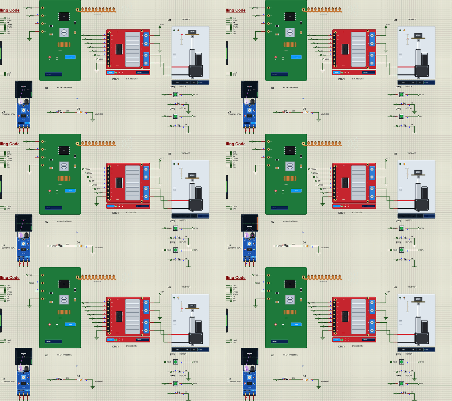
What Does This Garage Door Opener Do?
- A key fob: an ESP32 with an FS1000A 433 MHz transmitter and a button sends a new 32-bit code on every press.
- A rolling code: a counter that goes up with every press and a check made from it with a secret key; the opener refuses a wrong check and an old counter.
- A replay test: a second button sends the last code again, as a "code grabber" would, and the opener refuses it.
- Drives the door: a BTS7960 H-bridge moves a 12 V linear actuator, a scale model of the door's drive, with one button: open, stop, close.
- Feels the door: the BTS7960's current-sense pins tell the ESP32 the motor current - near zero when a limit switch has stopped the door, high when something is in the way.
- Keeps people safe: an obstacle or a broken IR beam makes a closing door open again; an amber lamp flashes while the door moves.
- A web dashboard: the door, the motor current, the codes accepted and refused, with BUTTON, OPEN and CLOSE, on a laptop or a phone.
It is a great project for learning radio remotes, the basics of message authentication, replay attacks, H-bridges, current sensing, and safety logic. In the simulation, the receiver's pop-up shows every burst it hears with the noise around it and lets you move it away from the transmitter; the transmitter's pop-up shows the frames it sent; the BTS7960's pop-up shows both half-bridges and the IS pins; the actuator's pop-up shows the rod, its speed, its current and a load you can put on it.
Components Used in the Proteus Simulation
All the parts come from our Proteus libraries, each with its own tutorial. The project zip at the end includes every LIB and DLL file.
| Part | Proteus device | Library post | Connection |
|---|---|---|---|
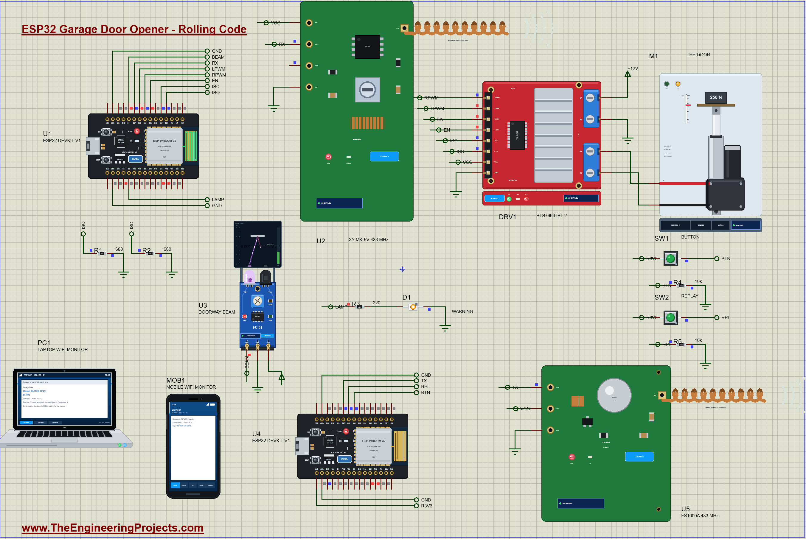
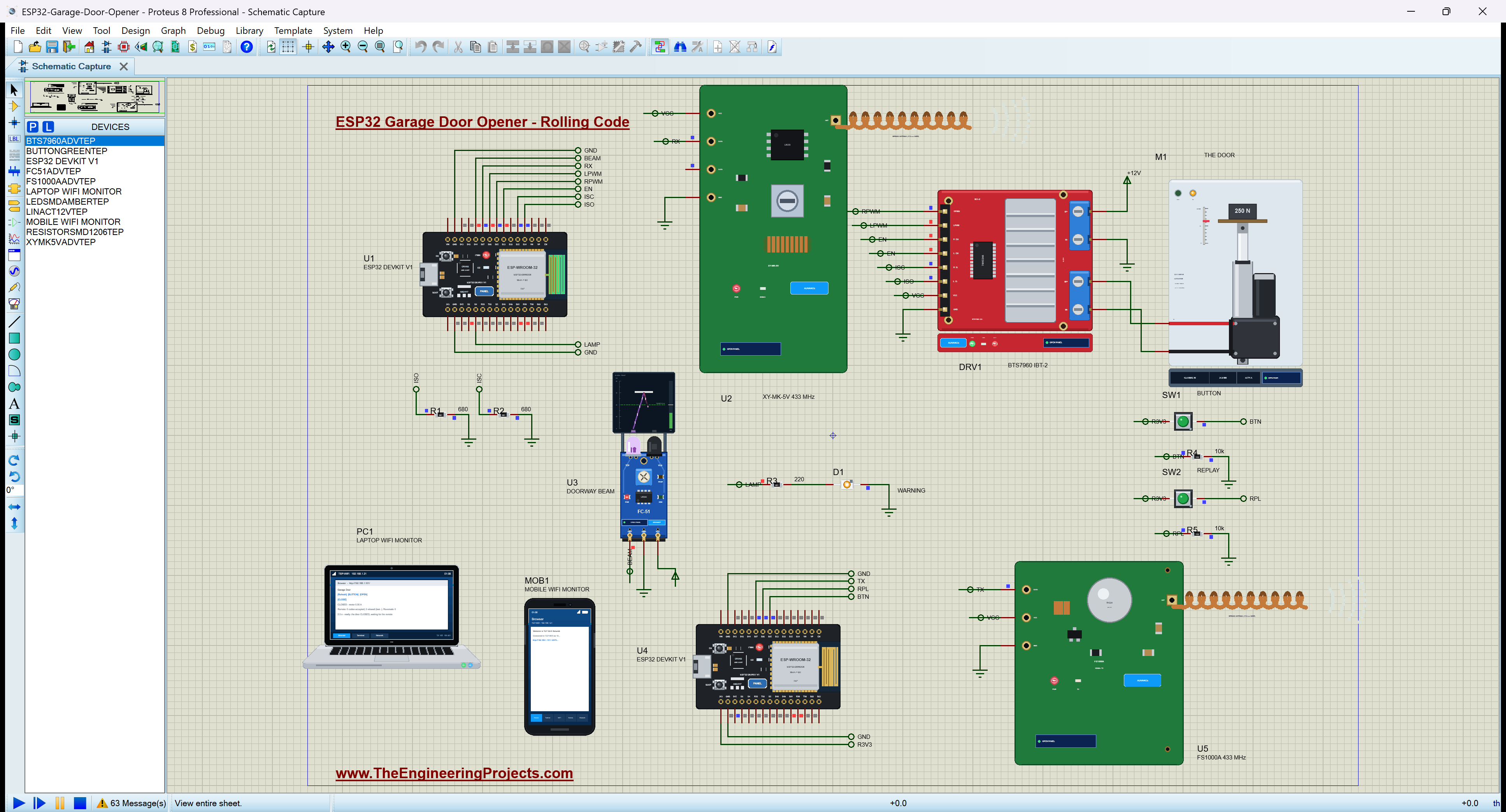
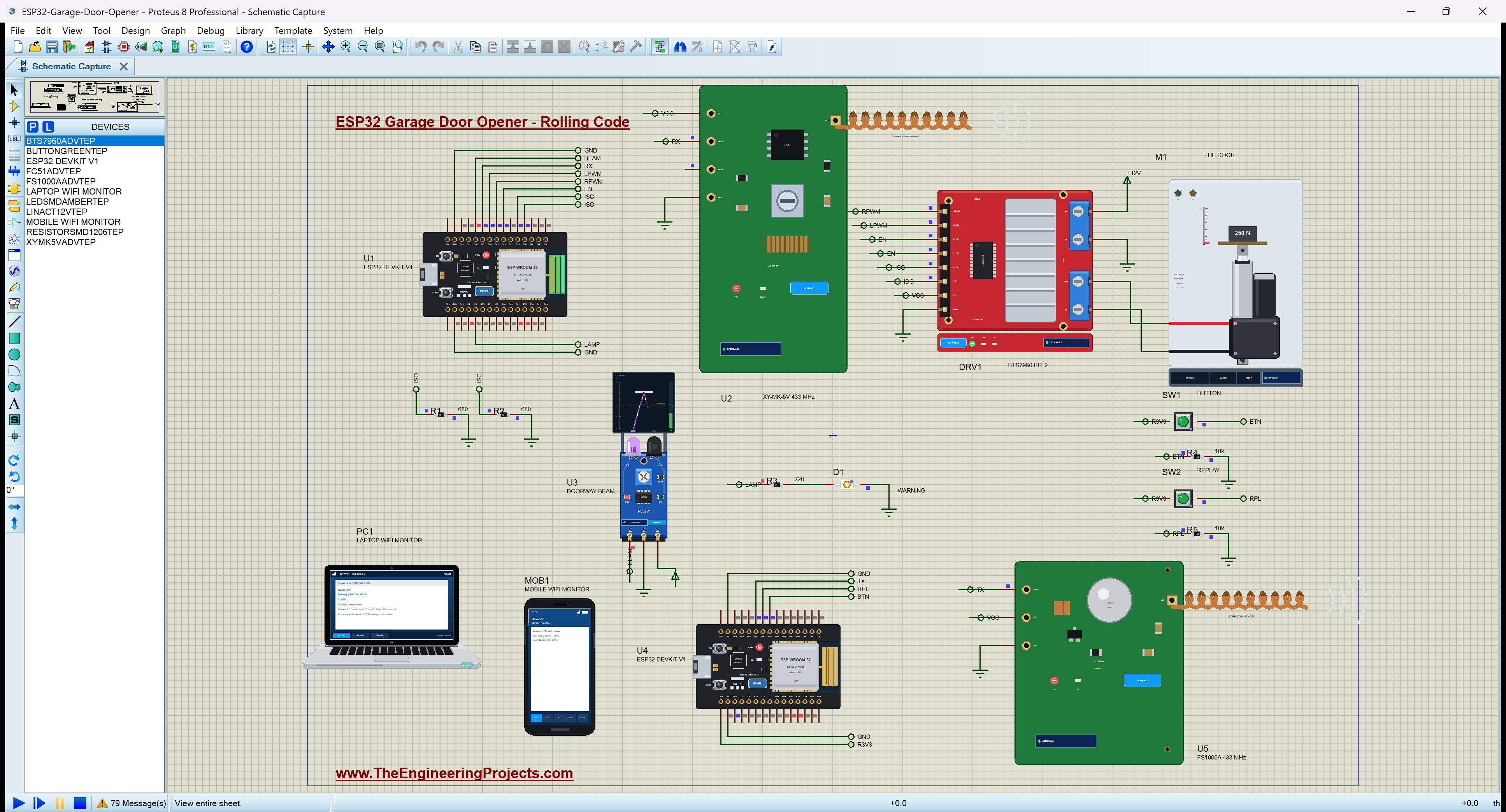
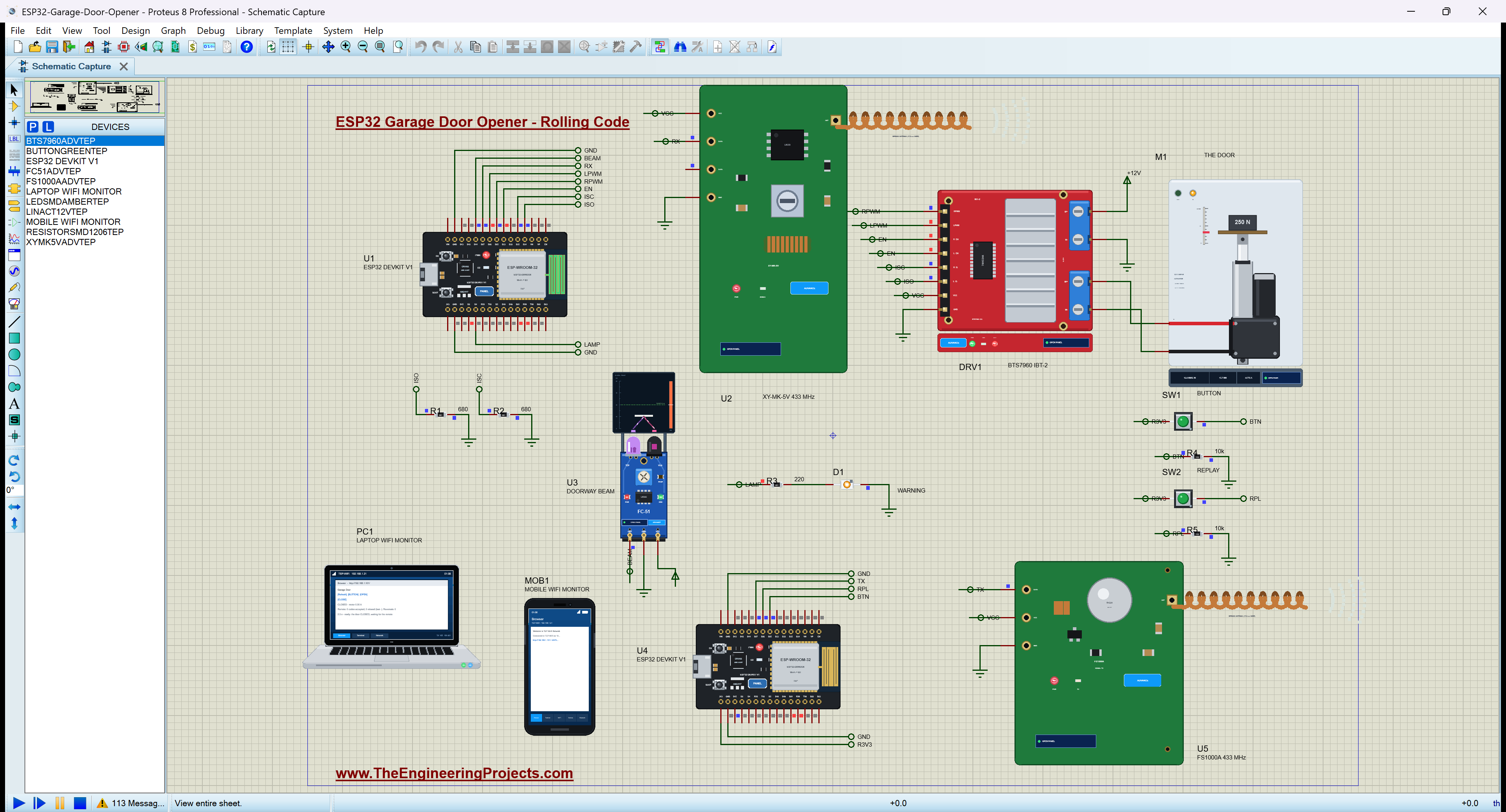
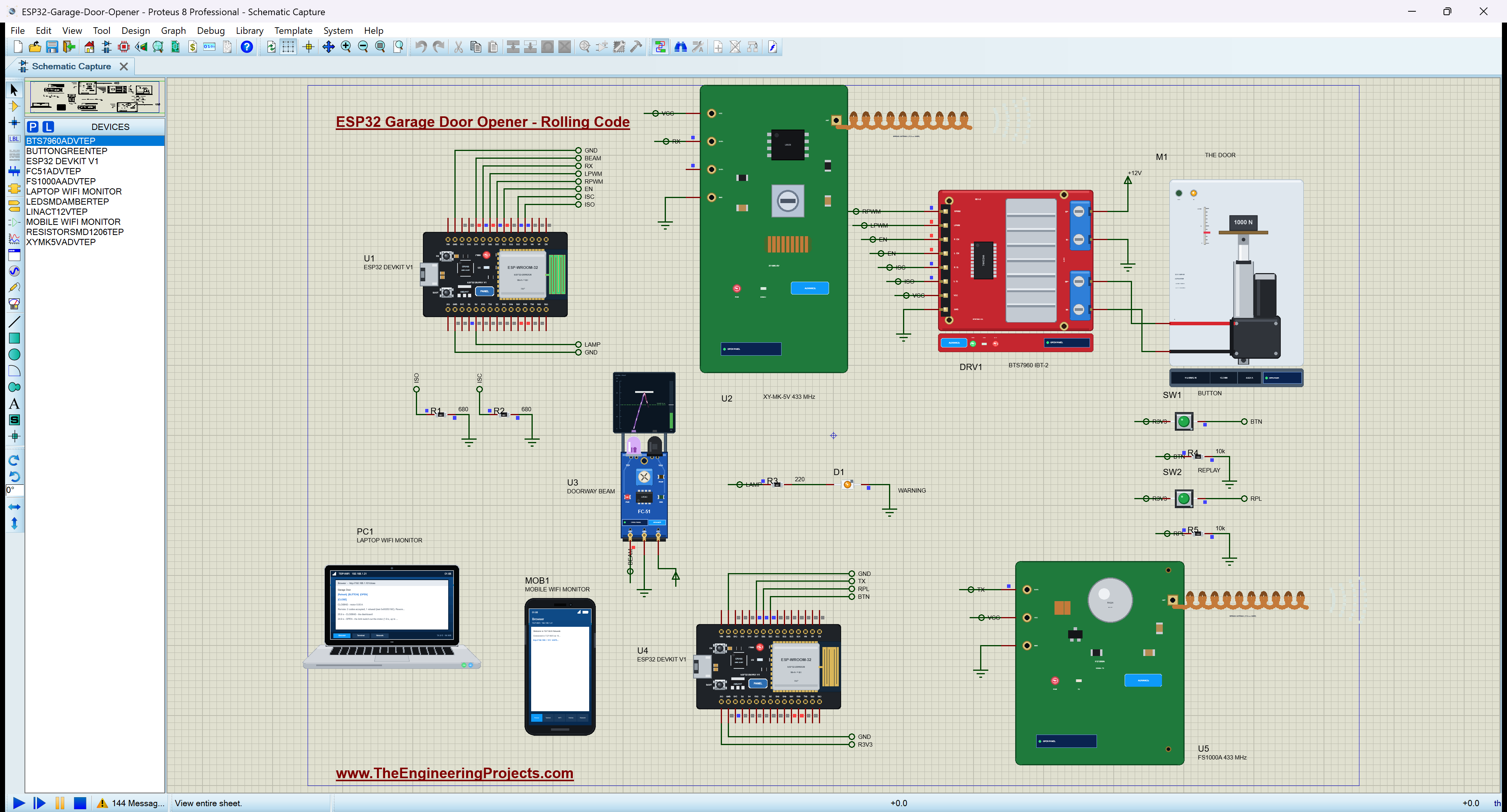
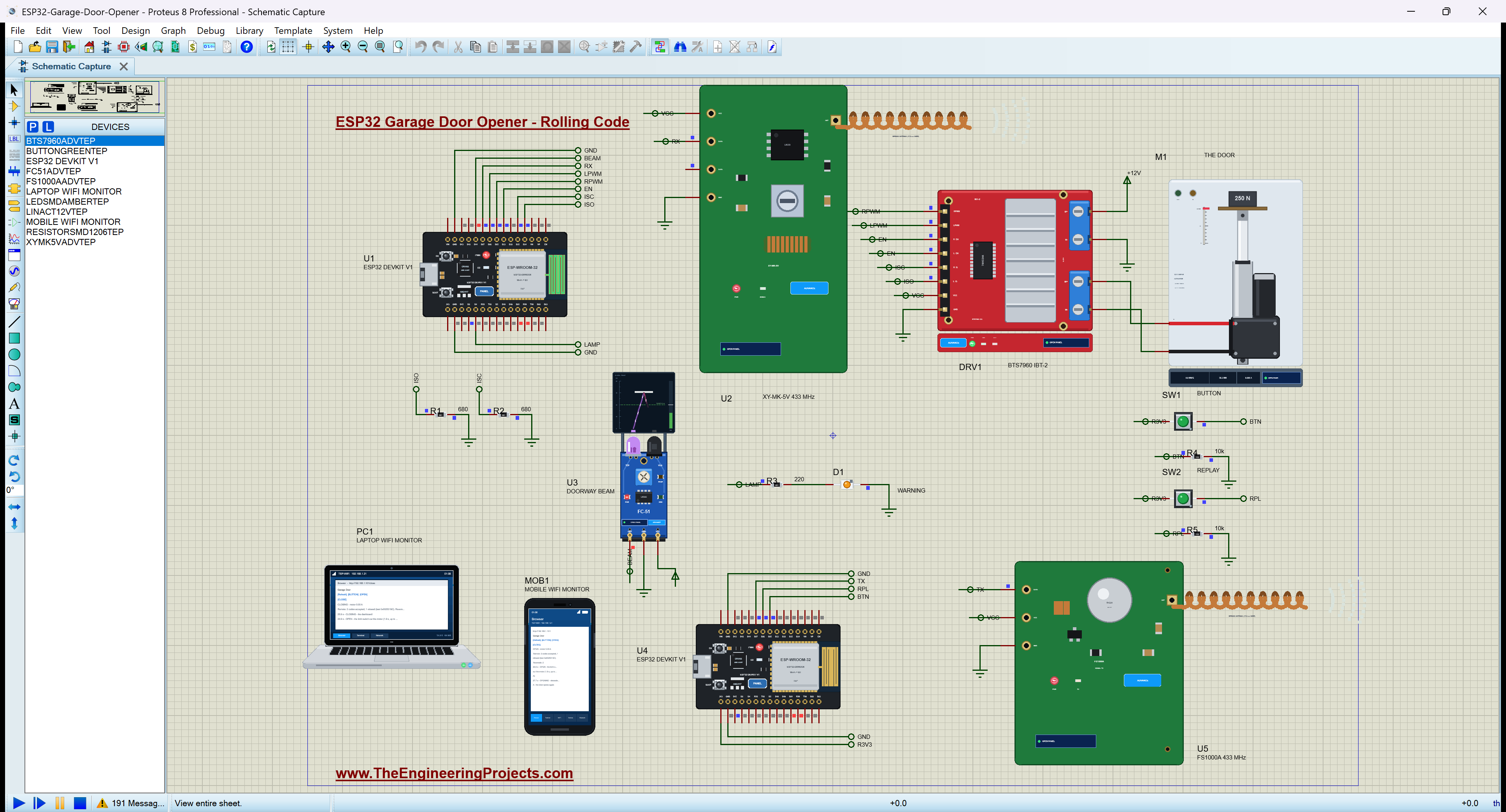
| ESP32 DevKit V1 (x2) | ESP32 DEVKIT V1 | ESP32 DevKit V1 Library for Proteus | U1 the opener (TEP-WiFi 192.168.1.101), U4 the remote |
| XY-MK-5V 433 MHz receiver | XYMK5VADVTEP | 433 MHz RF Module Library for Proteus | U2, DATA to D27 of U1 |
| FS1000A 433 MHz transmitter | FS1000AADVTEP | 433 MHz RF Module Library for Proteus | U5, DATA from D27 of U4 |
| BTS7960 motor driver (IBT-2) | BTS7960ADVTEP | BTS7960 Motor Driver Library | DRV1: RPWM D25, LPWM D26, EN D33, IS to D34 / D35 |
| 12 V linear actuator | LINACT12VTEP | 12V Linear Actuator Library | M1, the door, on M+ / M- |
| FC-51 IR sensor | FC51ADVTEP | IR Obstacle Sensor (FC-51) Library | U3, the doorway beam, OUT to D14 |
| SMD LED amber + resistors | LEDSMDAMBERTEP, RESISTORSMD1206TEP | SMD LED Library, SMD Resistor Library | D1 the lamp on D4; R1 / R2 680 ohm IS, R3 220, R4 / R5 10k |
| Push buttons (x2) | BUTTONGREENTEP | Push Button Library | SW1 BUTTON D25, SW2 REPLAY D26 of U4 |
| Laptop WiFi Monitor | LAPTOP WIFI MONITOR | Laptop WiFi Monitor | PC1 |
| Mobile WiFi Monitor | MOBILE WIFI MONITOR | Mobile WiFi Monitor | MOB1 |
Proteus Simulation of the Garage Door Opener: the Circuit
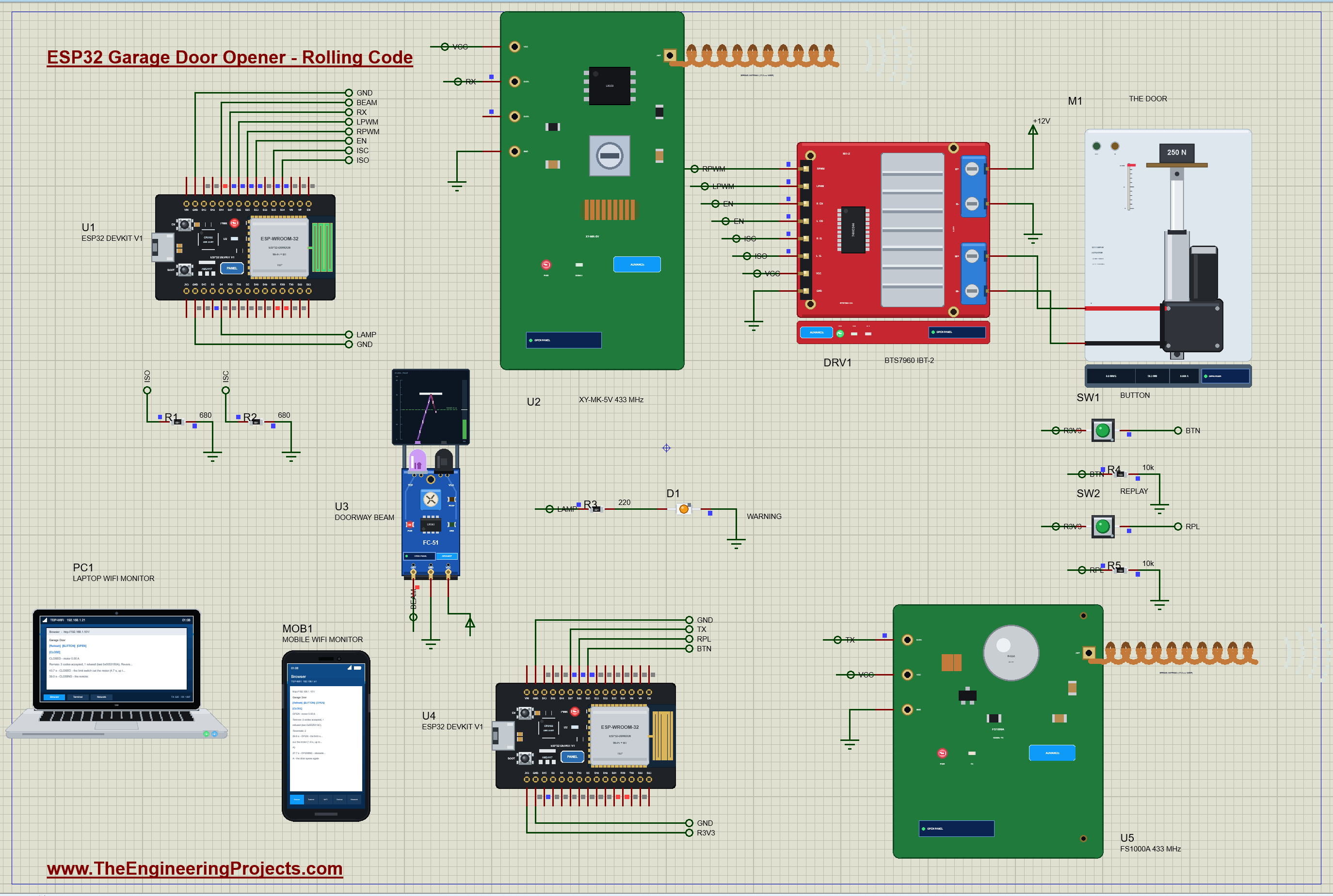
| Part | Pins | ESP32 / supply |
|---|---|---|
| U2 XY-MK-5V | DATA | D27 of the opener (rc-switch on an interrupt) |
| U5 FS1000A | DATA | D27 of the remote |
| DRV1 BTS7960 | RPWM / LPWM / R_EN + L_EN | D25 (close) / D26 (open) / D33 |
| DRV1 BTS7960 | L_IS / R_IS | D34 / D35, each with 680 ohm to GND |
| DRV1 BTS7960 | B+ / B- ; M+ / M- | +12 V / GND ; the actuator |
| U3 FC-51 | OUT | D14 (LOW = something in the beam) |
| SW1 / SW2 | to 3.3 V, 10k to GND | D25 / D26 of the remote |
The two boards share nothing but the air: in the simulation the 433 MHz modules hear each other, at a distance you set on the receiver's pop-up. The current-sense pins go to D34 and D35, ADC1 inputs that keep working with Wi-Fi on. In Proteus the 433 MHz modules and the BTS7960's logic take their supply from the default power rail, because their models read it as a logic level; on real boards the XY-MK-5V and the BTS7960's logic run on 5 V, and the FS1000A on 3.3 to 12 V.
How the Garage Door Opener Works
433 MHz ASK: a Carrier Switched On and Off
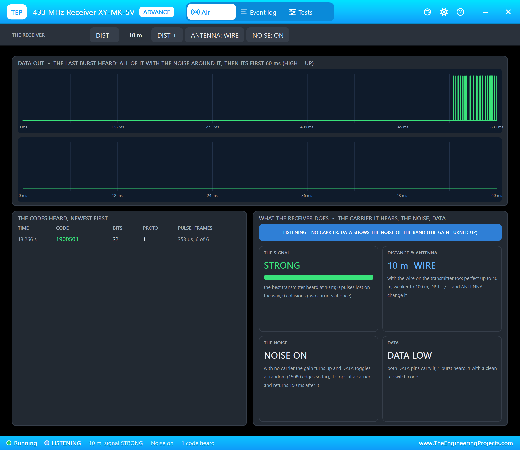
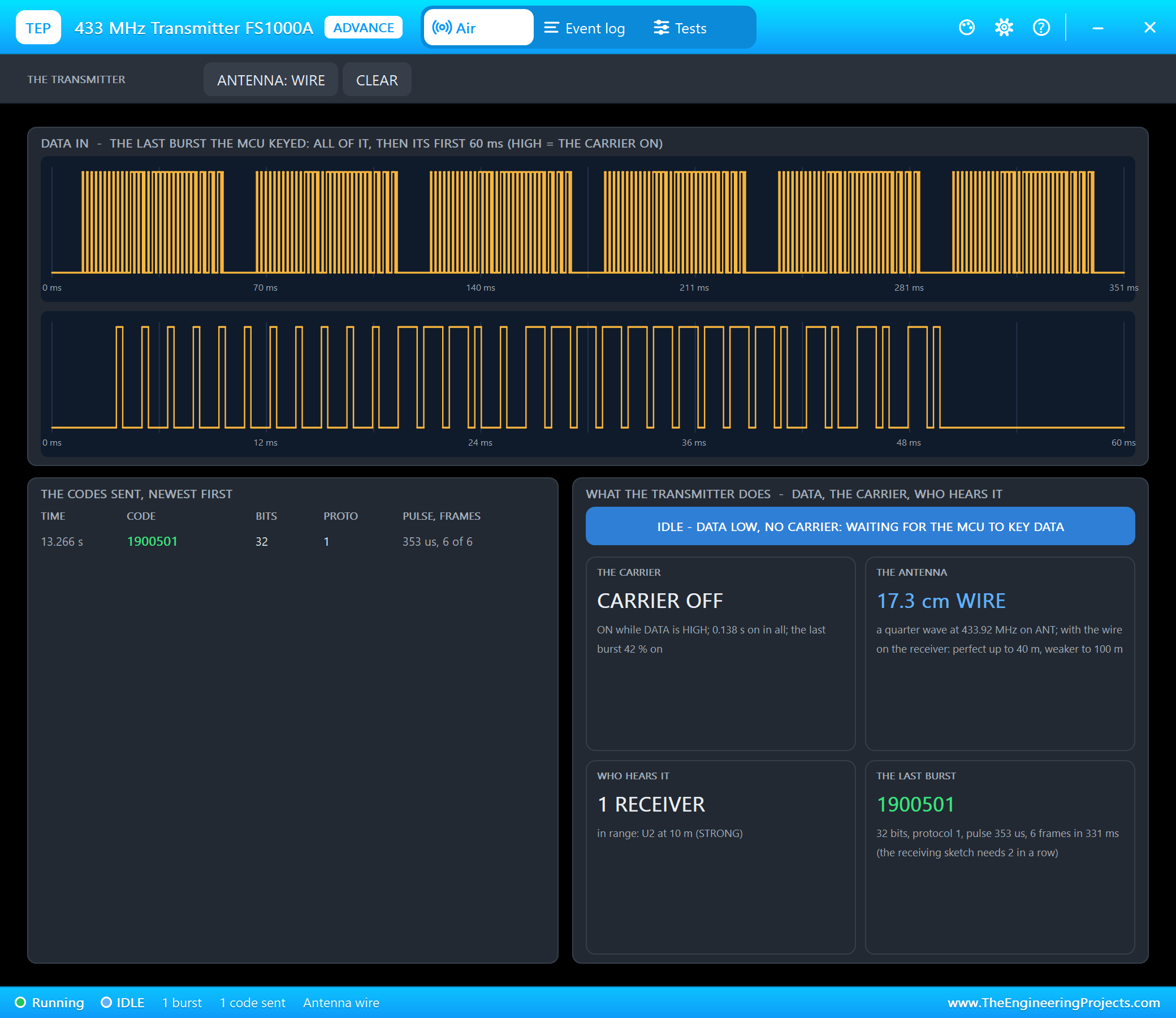
The FS1000A is about the simplest radio there is: while its DATA pin is high it sends a 433.92 MHz carrier, while it is low it sends nothing. That is amplitude-shift keying, or on-off keying. The XY-MK-5V turns the carrier back into a logic level, but with nothing to hear its gain rises until it turns the band's noise into random pulses on DATA. So a receiver never sees silence, and the decoder must recognise its message inside that noise. rc-switch does that with a fixed pattern: in protocol 1 a pulse unit T is about 350 us; a frame starts with a sync of 1 T high and 31 T low, and then every bit is 4 T long, 1 T high and 3 T low for a 0, 3 T high and 1 T low for a 1.
Worked example: a 32-bit code takes 32 x 4 x 0.35 = 44.8 ms, plus the 11.2 ms sync, about 56 ms a frame. The remote sends each code six times, so one press is about 0.34 s on the air; the transmitter's pop-up measured six frames in 331 ms. The repeats make the press survive a burst of noise, and the opener must not take frames two to six as new presses.
Why a Fixed Code Is Not Enough
A cheap remote sends the same code on every press. Anyone within range with a 433 MHz receiver and a microcontroller can record it once and send it again whenever they like; such a device is called a code grabber, and against a fixed code it always works. The answer is a code that is never the same twice and that only the real remote can make.
A Small Rolling Code
Every code here is 32 bits: a 12-bit counter in the top bits, and a 20-bit check below it. The counter goes up by one on every press. The check is made from the counter and a secret key that only this remote and its opener know, by eight rounds of mixing; without the key you cannot compute the check for a new counter. The opener keeps the last counter it accepted and takes a code only when the check is right and the counter is ahead of the last one, by 1 to 16. A recorded code carries an old counter, so it is refused, even though its check is perfect.
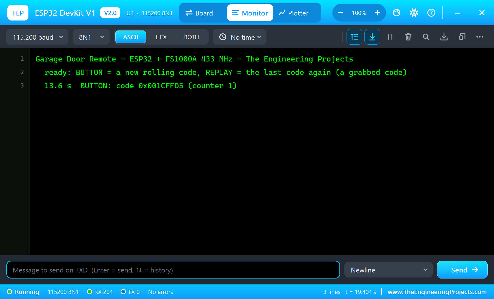
Worked example: the first press sends 0x001CFFD5. The top 12 bits, 0x001, are the counter, 1; the low 20 bits, 0xCFFD5, are the check. The opener computes the check for counter 1 with its key, finds 0xCFFD5, sees that 1 is ahead of 0, accepts the code and remembers 1. When the same 0x001CFFD5 comes back later, its counter is 1 again, not ahead: refused, "a replay".
Presses Out of Range: the Window
A fob gets pressed in a pocket, or too far away. Its counter goes up, the opener hears nothing, and the two drift apart. That is why the opener accepts a counter up to 16 ahead: the next press it does hear is accepted and the opener catches up. Real systems do the same, with a small window for normal use and a resynchronisation procedure, two presses in a row, for counters far ahead. The scheme here is a teaching one: real remotes use KeeLoq, with a 66-bit code, or AES with longer keys, but the idea of a counter protected by a secret is the same.
The BTS7960 and Its Current Sense
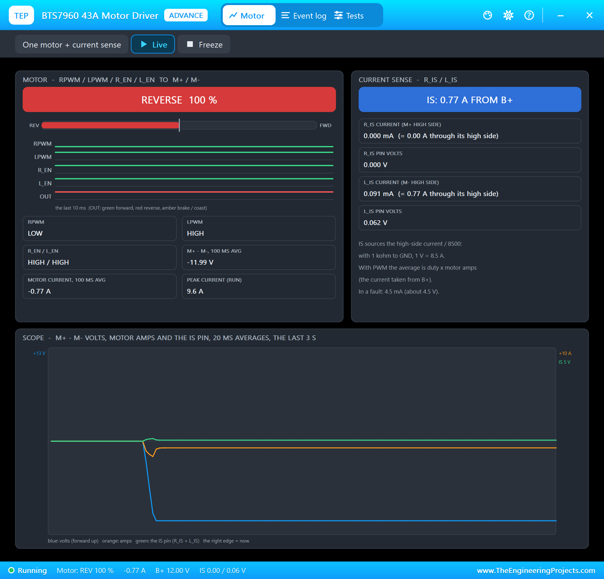
The BTS7960 module holds two BTS7960 half-bridges, one per motor terminal; RPWM and LPWM switch them, and R_EN and L_EN enable them. Each half-bridge also has an IS pin that sources a small copy of the current through its high-side switch: the current divided by about 8500. With 680 ohm to ground, that copy becomes a voltage the ESP32 can read. Worked example: 0.78 A through the motor gives 0.78 / 8500 = 92 uA, and 92 uA x 680 ohm = 62 mV on the IS pin, about 77 counts on the ESP32's 12-bit ADC. At 3 A it is 240 mV. The opener reads the IS pin of the half-bridge that is driving and turns it back into amps: I = V / 680 x 8500.
The Door: a Linear Actuator with Limit Switches
The door here is a 12 V linear actuator, a small motor turning a lead screw that pushes a rod 50 mm out and in, a scale model of the drive of a real door. It moves at about 12 mm/s, and its screw is self-locking: the door's weight cannot push it back. Inside it, a limit switch at each end cuts the motor. The rod out is the door down, closed; the rod in is the door up, open; the door's weight, 250 N here, pushes the rod in, so closing works against it and opening is helped by it.
Finding the Ends and the Obstacles from the Current
The opener has no switches of its own on the door: it reads the motor current. When the actuator reaches an end, its limit switch opens and the current drops to zero; under 0.1 A for 200 ms means the door is there. When the door meets something, the motor works harder and draws more current: over 2 A for 150 ms is an obstacle. A closing door that hits an obstacle opens again; an opening one stops. One complication: every motor draws a big inrush current for a moment when it starts, much more than when it runs, so the first 300 ms of every move are ignored. Safety standards for real openers, such as UL 325 in the US, ask for exactly these two things: the door reverses when it meets an obstruction, and an external sensor such as a photo-eye stops it from closing on someone.
The Safety Beam and the One-Button Cycle
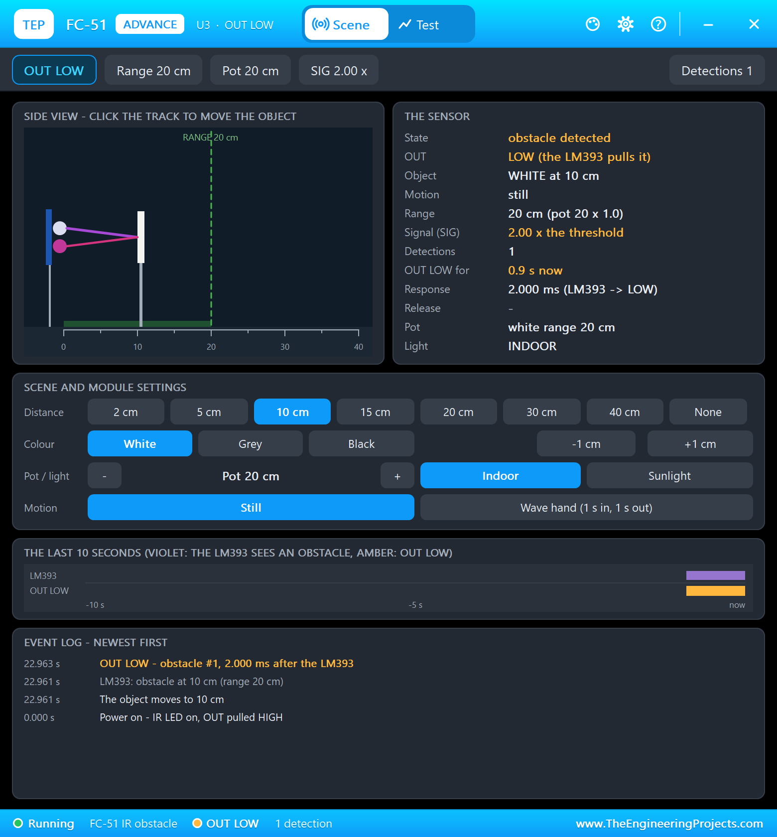
The FC-51 looks across the doorway; something in the beam pulls its output low, and a closing door then opens again at once. The opener follows the one-button cycle every garage door has: a press on a closed door opens it, on an open door closes it, on a moving door stops it, and on a stopped door sends it the other way. The amber lamp flashes twice a second while the door moves.
The Arduino Code Explained
Both sketches are included in the download: ESP32_Garage_Remote for the key fob and ESP32_Garage_Opener for the opener. Both use rc-switch for the 433 MHz link and share the same secret key and the same check:
const uint32_t SECRET = 0x5A17C3E9; // the key shared with the opener (set when they are paired)uint32_t check(uint16_t c) { // the 20-bit check: 8 rounds mixing the counter with the key
uint32_t v = c;
for (int i = 0; i < 8; i++) {
v += ((v << 4) ^ (v >> 5)) + (SECRET ^ (0x9E3779B9u * (i + 1)));
v ^= v >> 11;
}
return v & 0xFFFFF;
}The Remote
A press moves the counter on and builds the code; REPLAY sends the last code again, unchanged:
uint32_t codeFor(uint16_t c) { return ((uint32_t)(c & 0xFFF) << 20) | check(c & 0xFFF); } counter = (counter + 1) & 0xFFF;
lastCode = codeFor(counter); tx.send(code, 32); // 32 bits, protocol 1 (350 us pulses), REPEATS framesThe Opener
Frames two to six of the same press are dropped first; then the check, then the counter:
if (code == lastValue && millis() - lastAt < REPEAT_MS) { lastAt = millis(); return; } // the same press, its next frame if ((code & 0xFFFFF) != check(c)) { refused++; logEvent(String("code ") + hex + " refused: the check does not match (not our remote)"); return; }
if (ahead == 0 || ahead > WINDOW) {The motor current comes from the IS pin of the half-bridge that is driving:
return mv / R_IS * K_ILIS / 1000.0; // ampsWhile the door moves: the inrush ignored, the beam, the end of travel, the obstacle:
if (t < INRUSH_MS) return; // the start-up inrush: not an obstacle if (state == CLOSING && digitalRead(BEAM_PIN) == LOW) { reversals++; go(OPENING, "something in the beam - the door opens again"); return; } if (state == CLOSING) { reversals++; go(OPENING, "obstacle: " + String(amps, 2) + " A - the door opens again"); }The dashboard's pages are / (the dashboard), /button (the same as the remote's button), /open, /close, /stop and /data (everything as JSON). Both boards print every code, every decision and every move on their serial monitors.
How to Run the Proteus Simulation
- Download the project zip below and install the library files (the steps are under the download button).
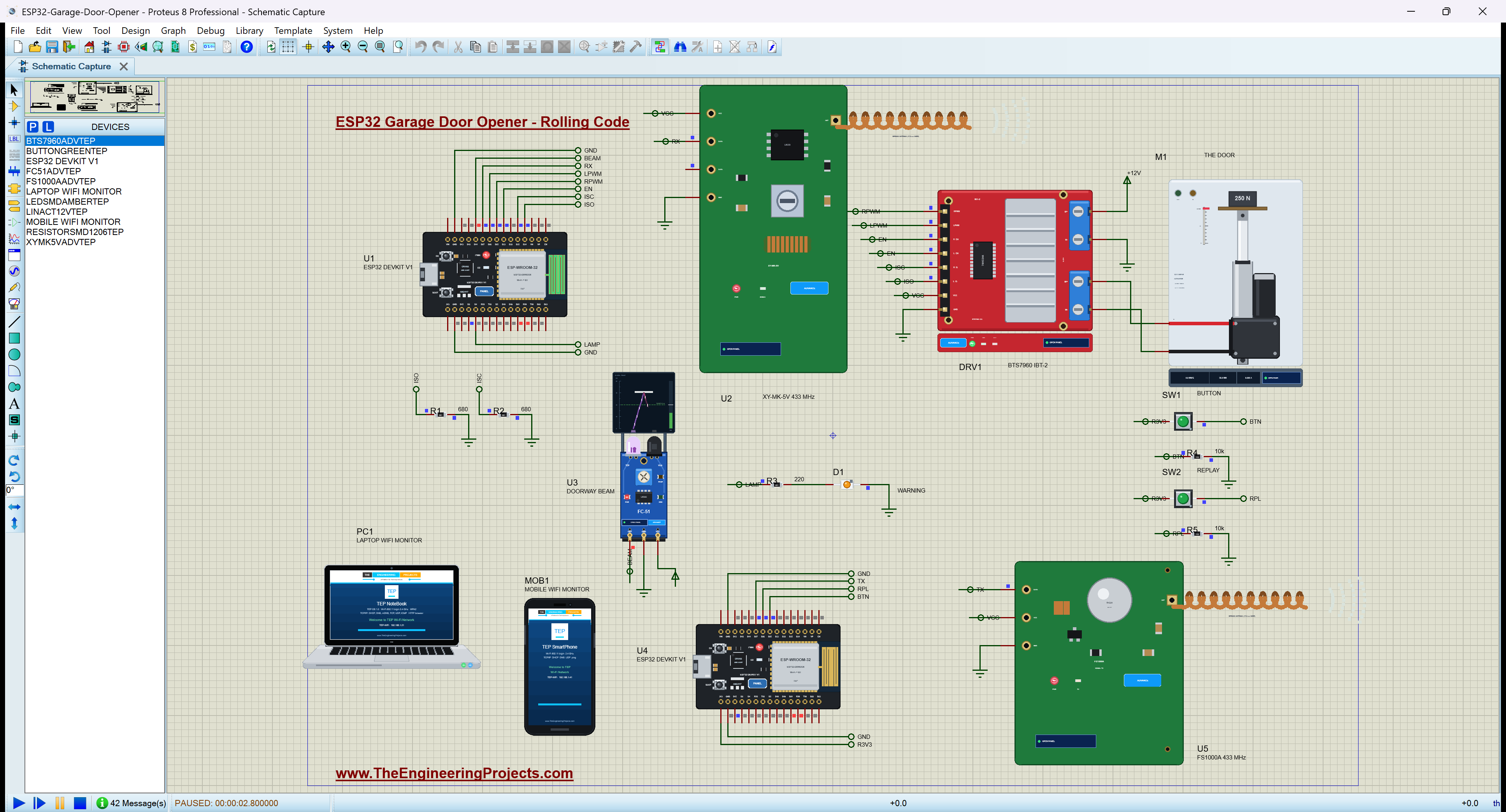
- Open ESP32-Garage-Door-Opener.pdsprj from the Proteus Simulation folder. Keep both HEX files and the DLL files next to it.
- Press Play. The door is closed. On the remote's BUTTON (SW1) pop-up, press Press: the door opens.
- Press REPLAY (SW2): the opener refuses the old code.
- Press BUTTON again and, while the door closes, bring the FC-51's object close, or choose 1000 N on the actuator's pop-up: the door opens again.
- On the receiver's pop-up, press DIST + until it is 150 m away and press BUTTON twice; come back to 10 m and press it once more.
- Open the Laptop or the Mobile WiFi Monitor and press Go for the dashboard.
Simulation Results: the Garage Door Opener in Proteus
Here is the run that made the screenshots of this tutorial, 46 seconds of simulation: the door opened by the remote, a replayed code, the beam, an obstacle, and the remote out of range and back. The times are the sketches' own clocks, as they printed them on the two serial monitors; the parts' numbers come from their pop-ups.
The Door Closed
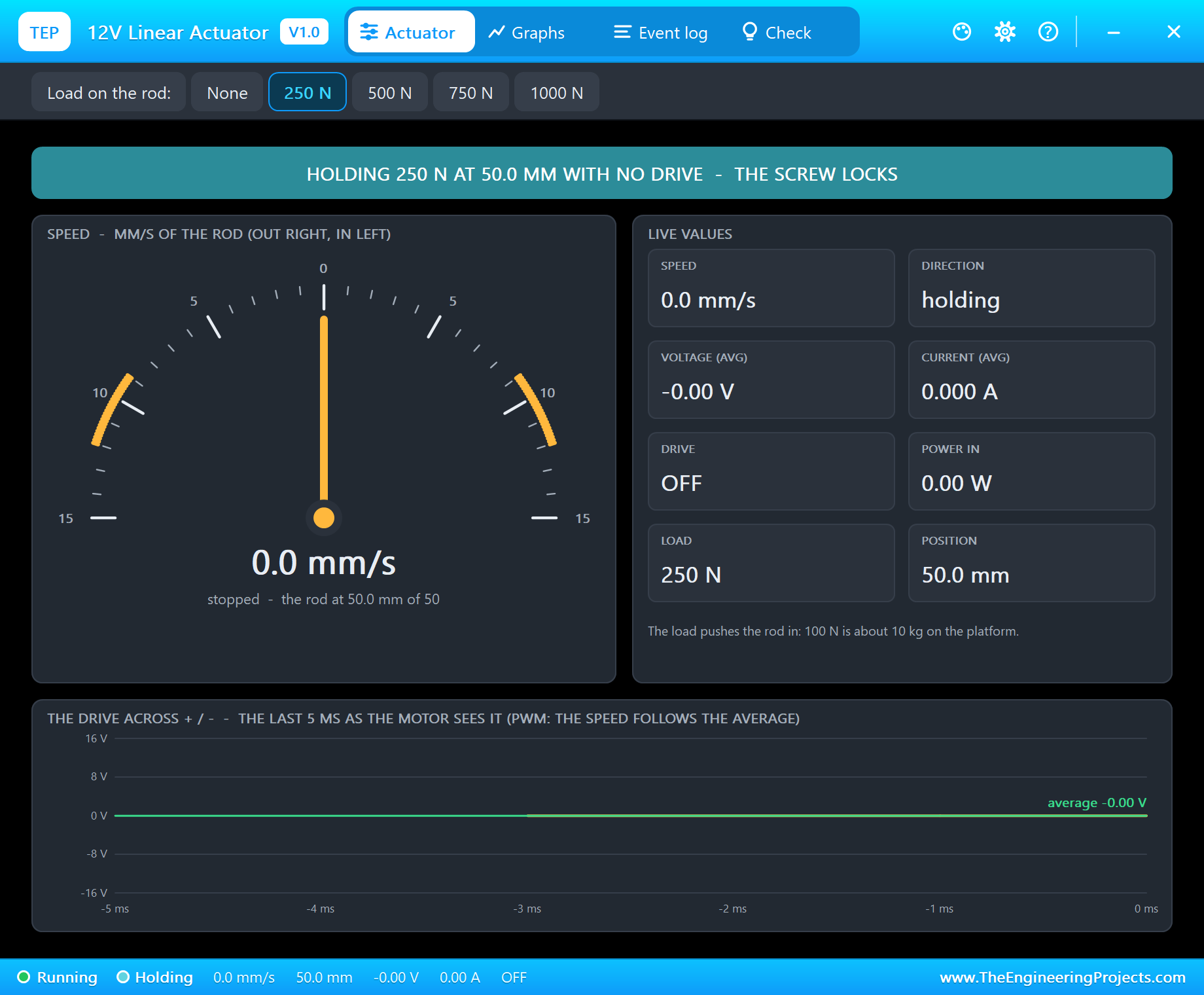
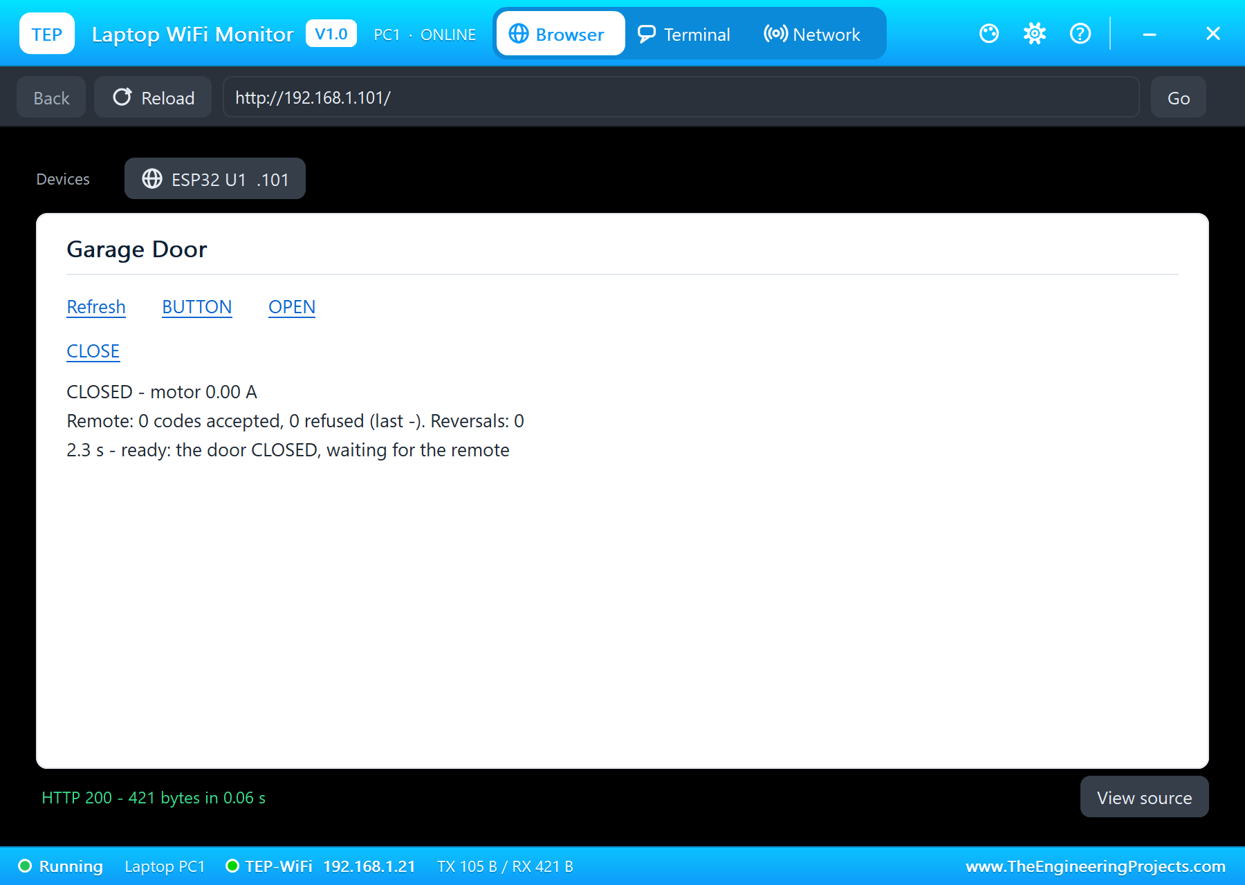
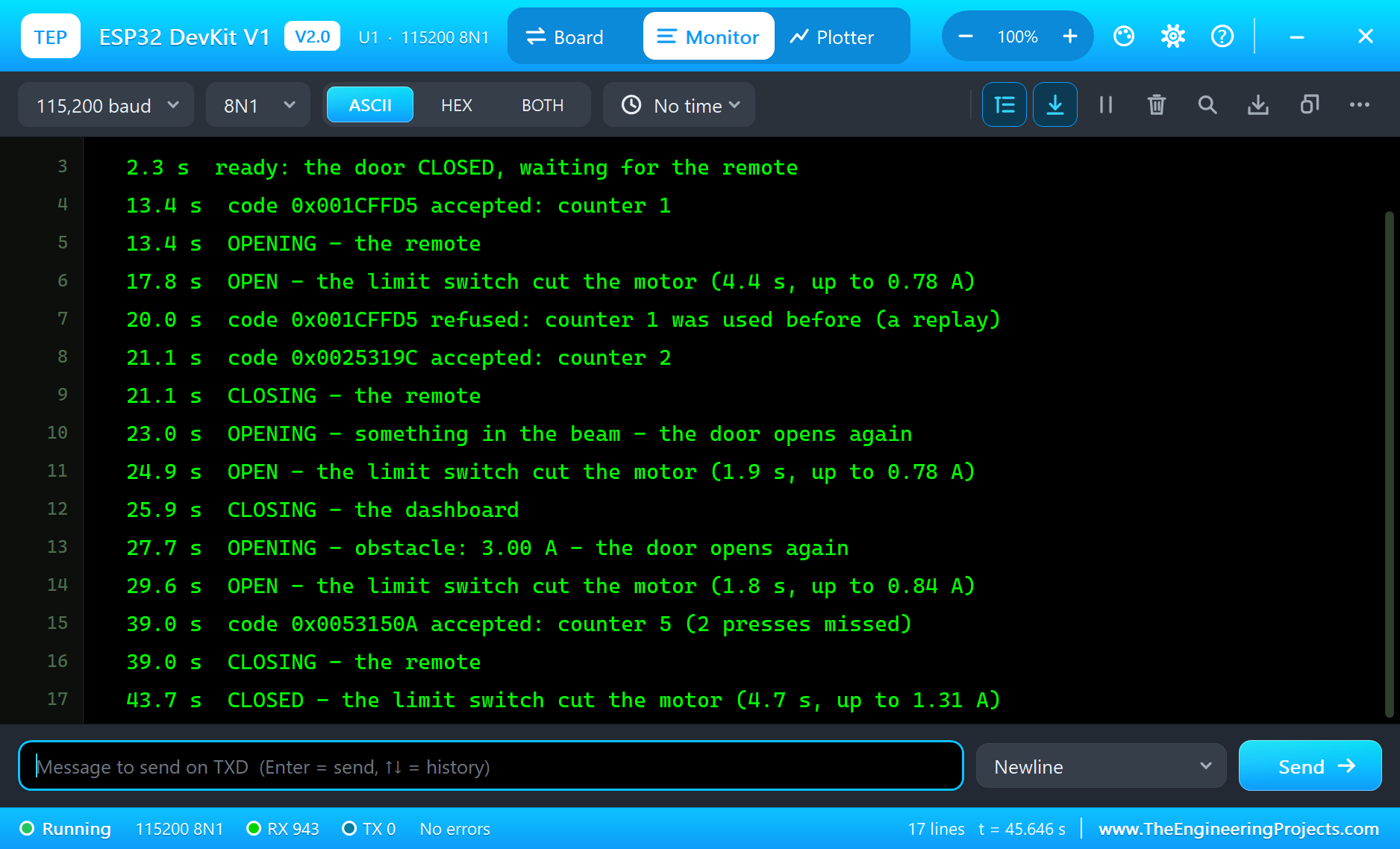
At the start the actuator's rod is fully out, 50 mm: the door is down. Its pop-up shows it holding the door's 250 N with no drive at all, "the screw locks": the lead screw cannot be pushed back, so a closed door stays closed without power. The opener joins TEP-WiFi, and at 2.3 s: "ready: the door CLOSED, waiting for the remote".
BUTTON: a Rolling Code Opens the Door
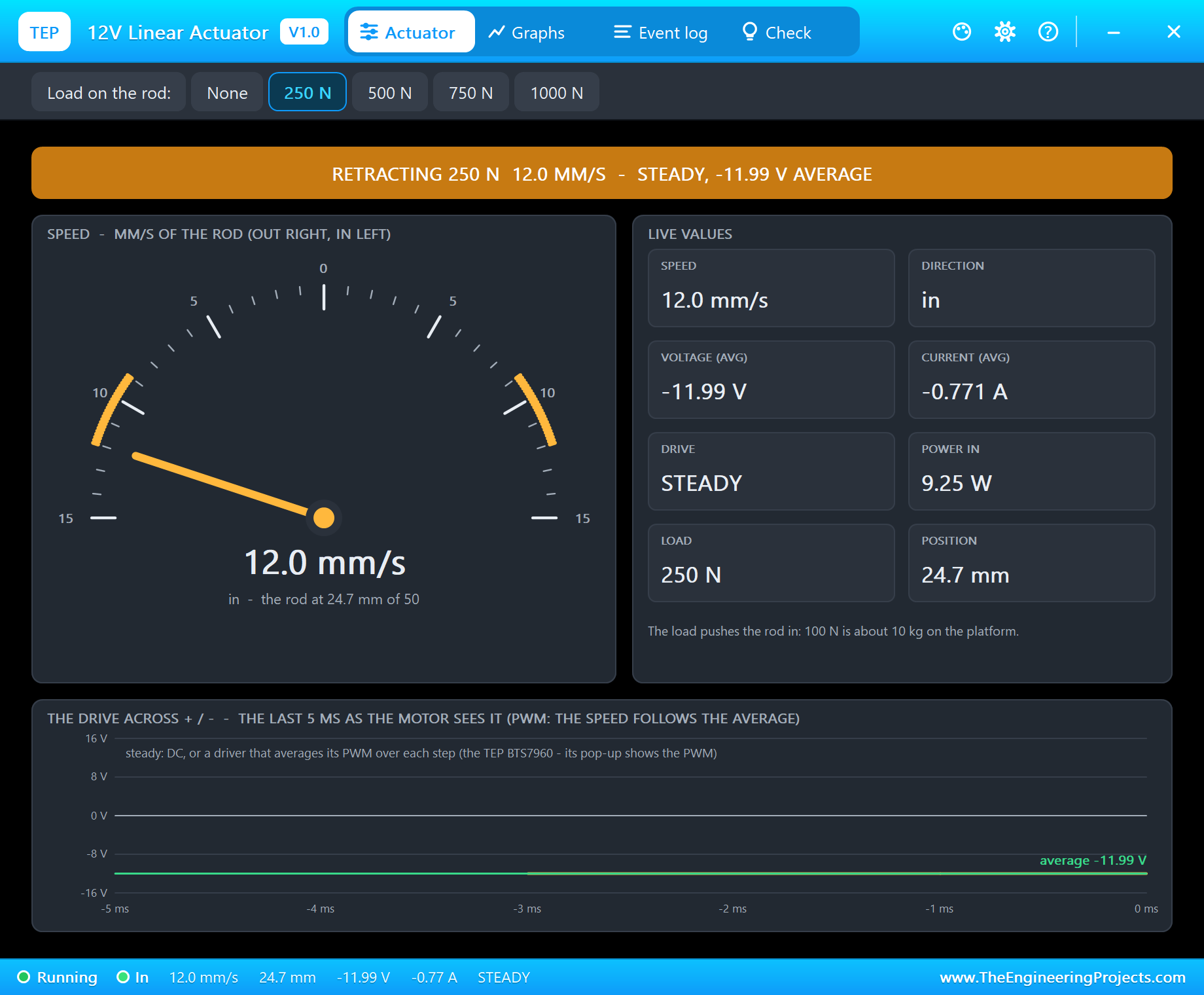
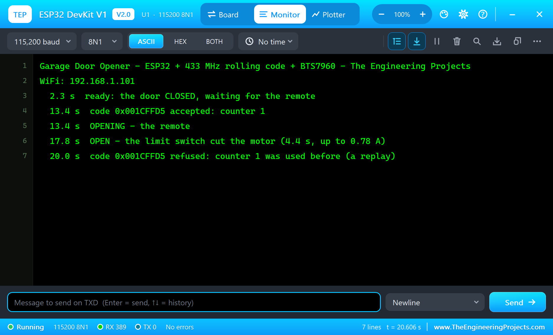
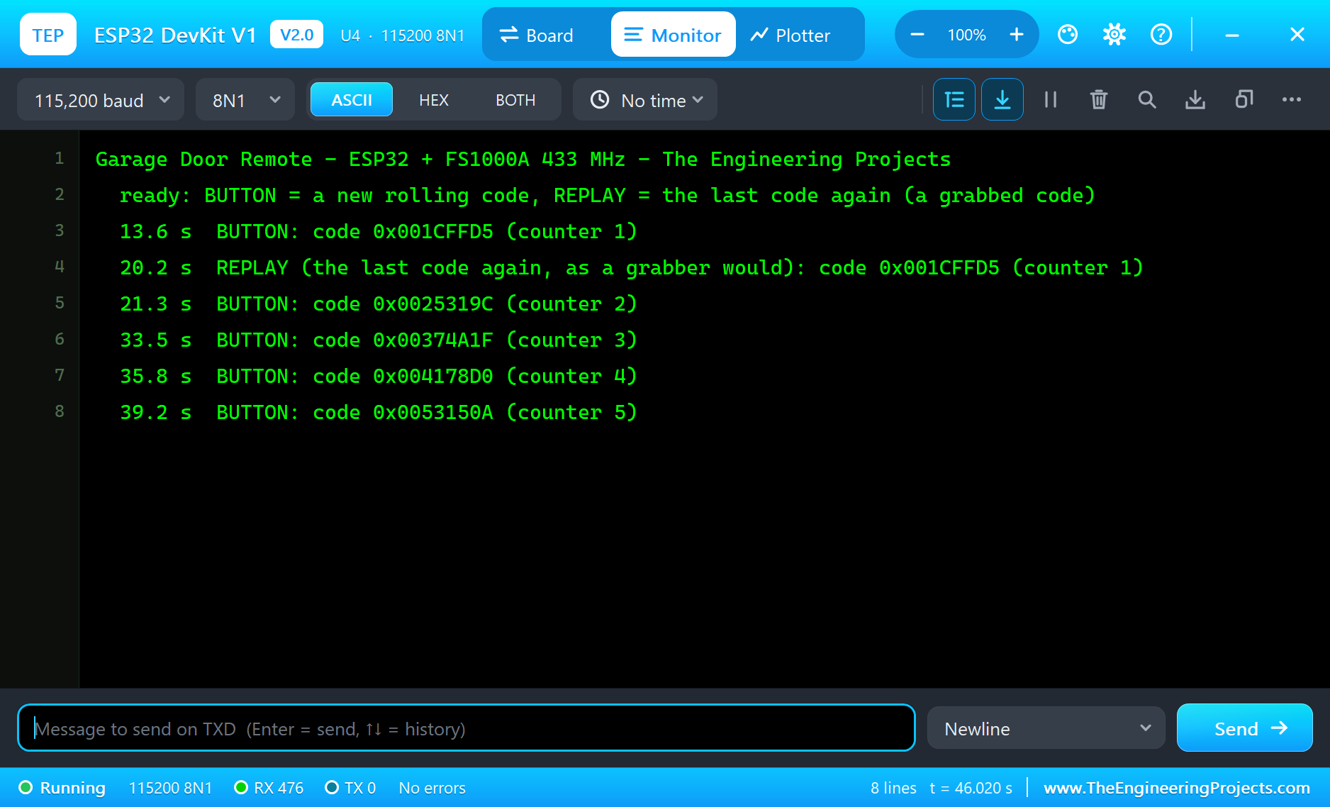
The remote's first press sends code 0x001CFFD5, counter 1. The opener checks it and at 13.4 s: "code 0x001CFFD5 accepted: counter 1", "OPENING - the remote". The BTS7960 drives LPWM, the rod comes in at 12 mm/s, and the amber lamp flashes. The BTS7960's pop-up shows 0.77 A through the left half-bridge and 0.062 V on L_IS, exactly the 62 mV of the worked example above; at the very start it caught a peak of 9.6 A, the inrush the opener ignores. At 17.8 s the rod reaches the end, the actuator's limit switch opens and the current falls to zero: "OPEN - the limit switch cut the motor (4.4 s, up to 0.78 A)". The receiver's pop-up shows the code heard, 32 bits, protocol 1, a 353 us pulse, all six frames; the transmitter's, the six frames it keyed in 331 ms.
REPLAY: a Grabbed Code Is Refused
Now the remote's REPLAY button sends 0x001CFFD5 again, word for word, what a code grabber would do with a recording. The check is perfect, because it is a real code; but its counter is 1, and the opener has already used counter 1. At 20.0 s: "code 0x001CFFD5 refused: counter 1 was used before (a replay)". The door does not move.
The Beam: Something in the Doorway
The second press, counter 2, is accepted at 21.1 s and the door starts down. Then something steps into the doorway: the FC-51 sees an object at 10 cm and pulls its output low. At 23.0 s: "OPENING - something in the beam - the door opens again", and at 24.9 s the door is open once more.
An Obstacle: the Current Rises
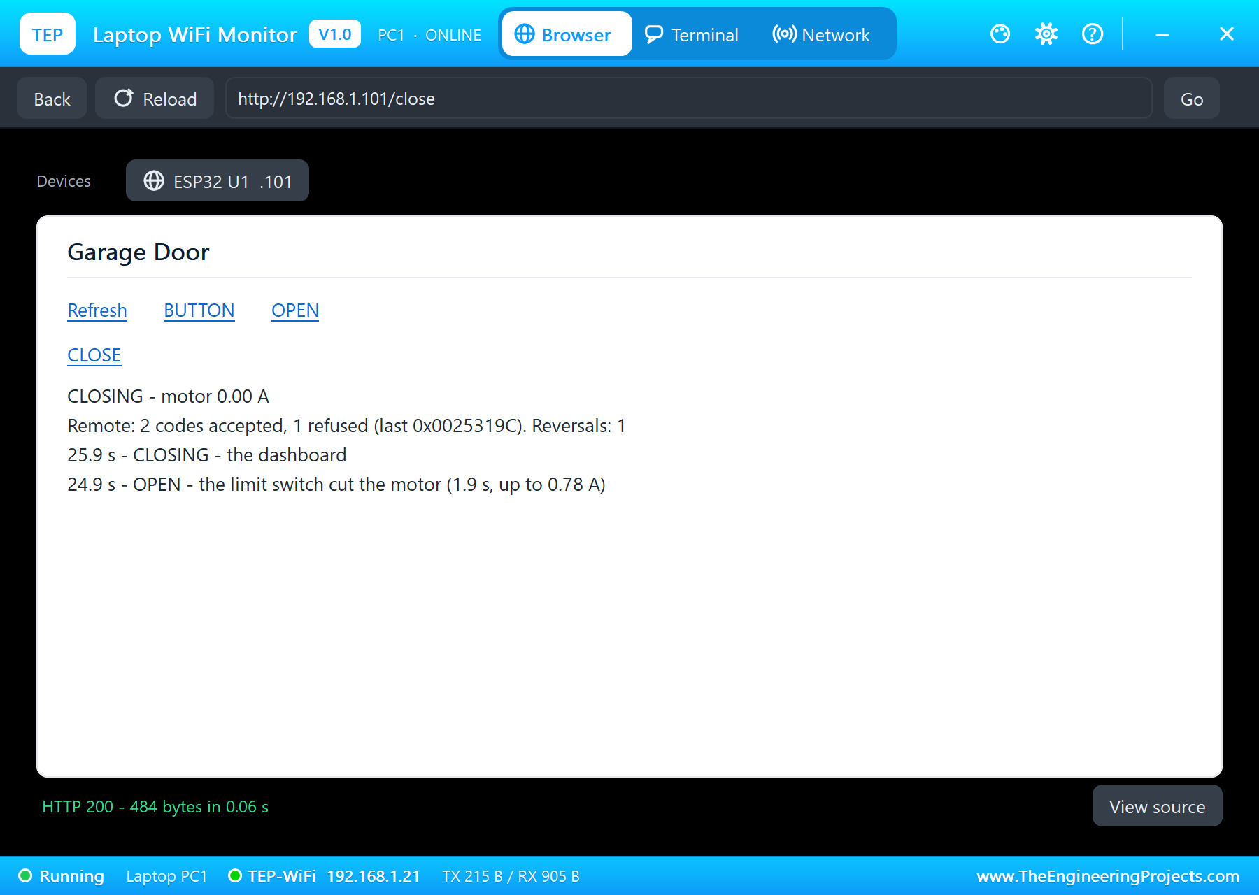
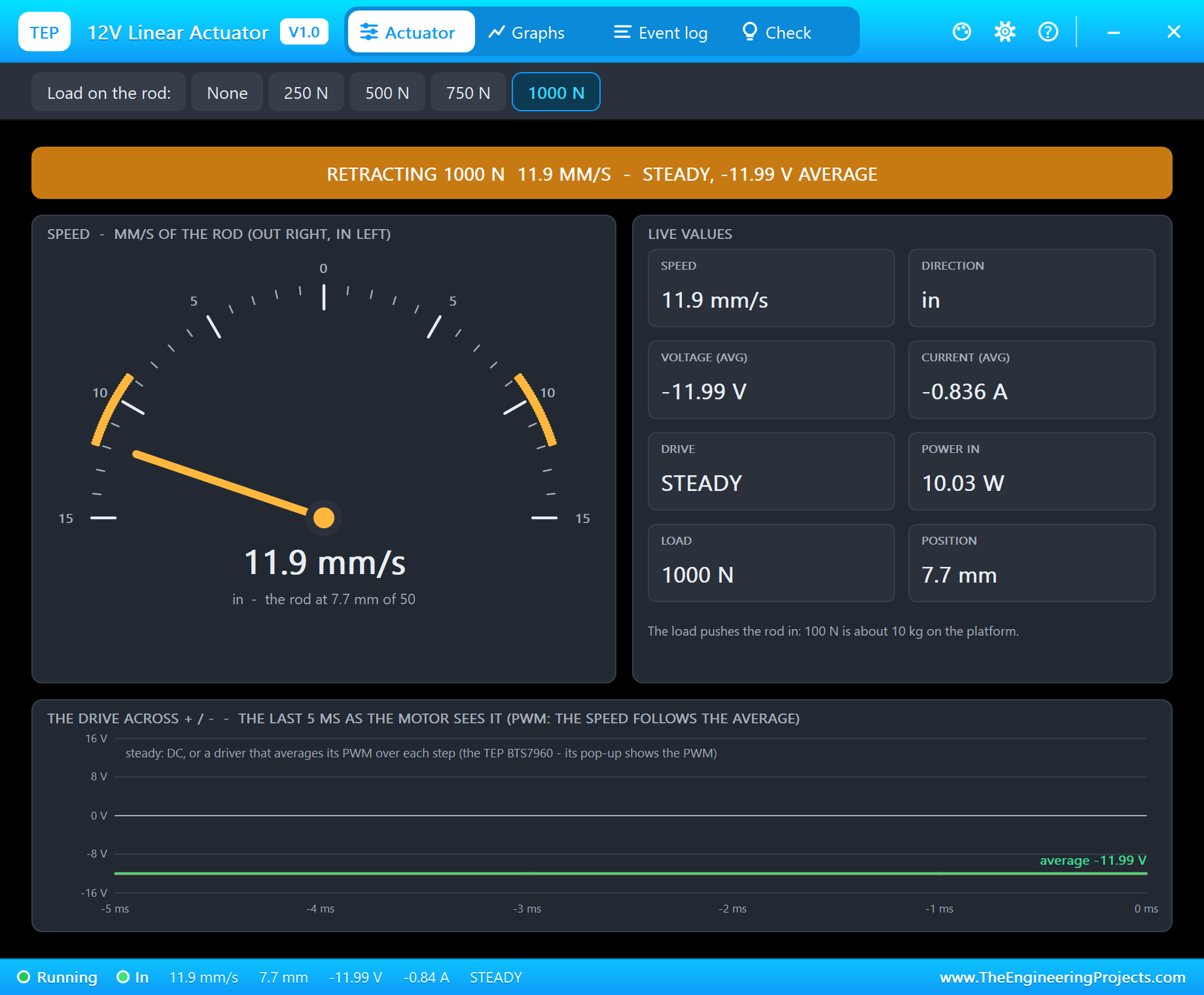
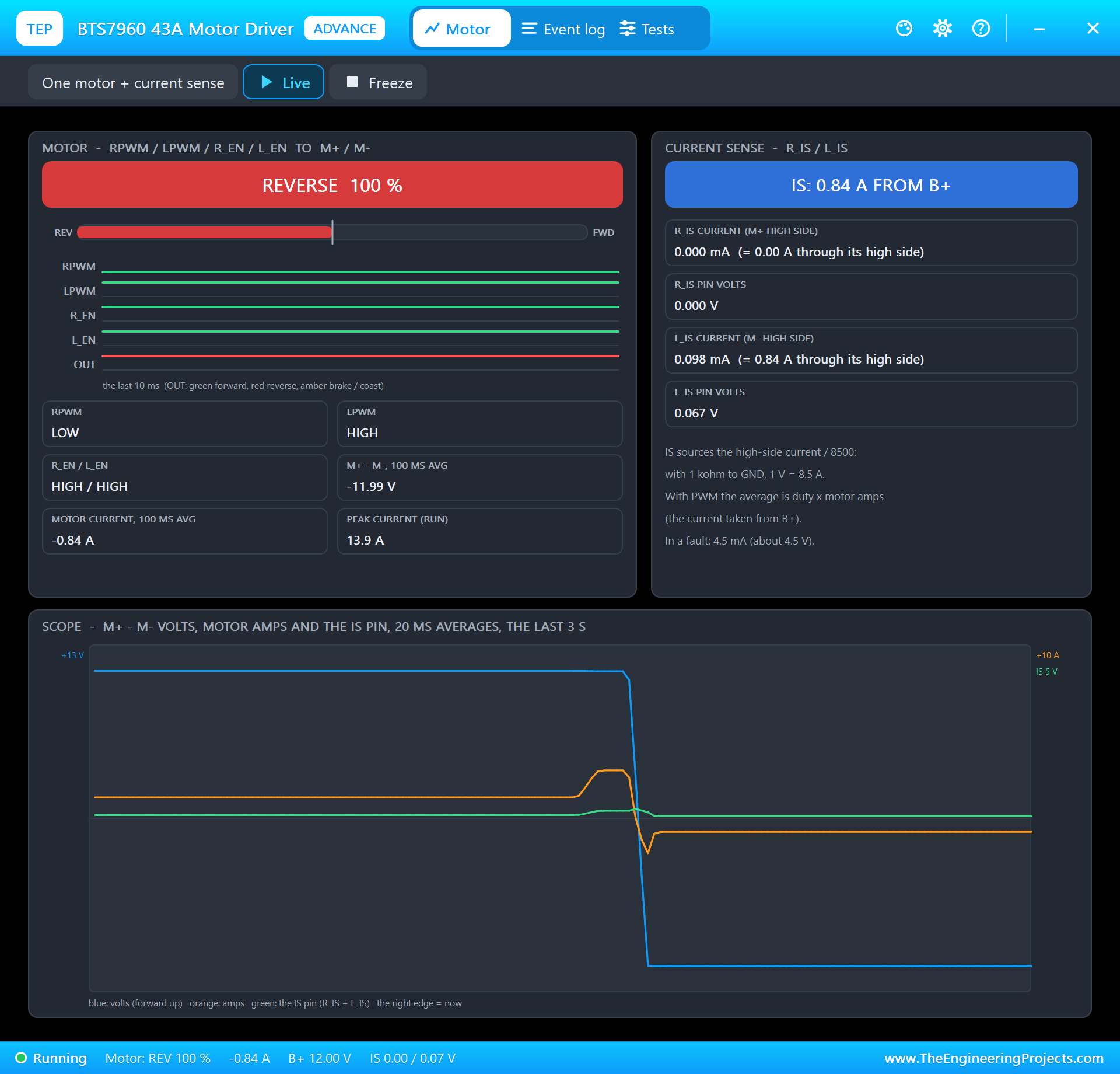
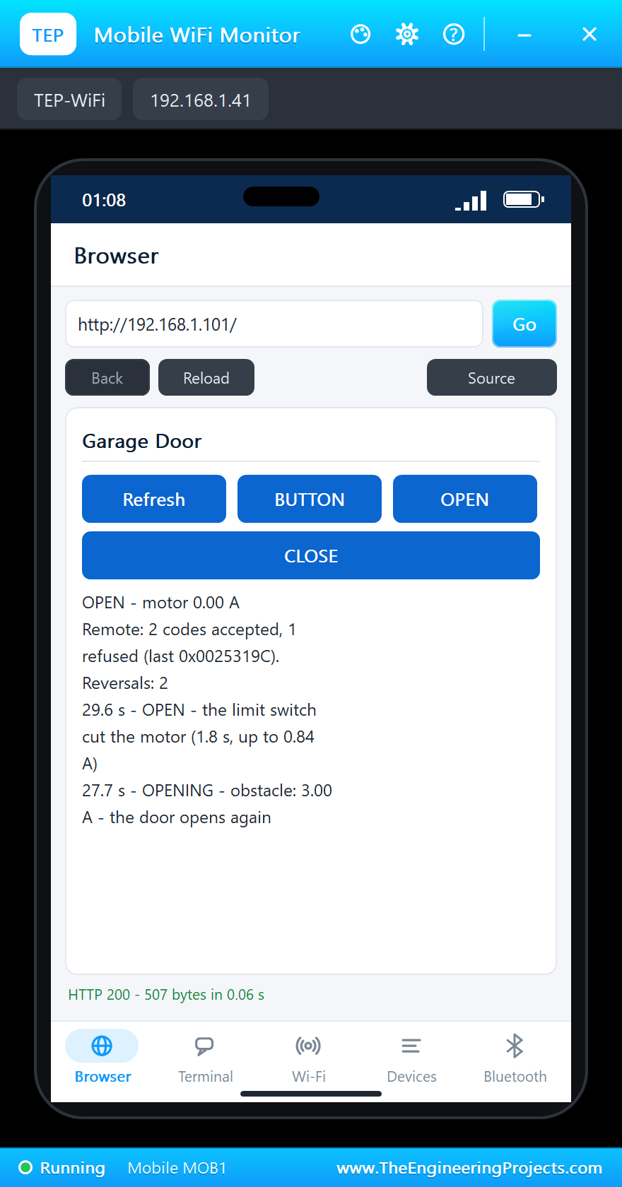
With the beam clear, CLOSE on the laptop starts the door down at 25.9 s. This time something heavy is in the way: on the actuator's pop-up the load goes up to 1000 N while the rod pushes out. The motor works harder, the current climbs past 2 A, and at 27.7 s: "OPENING - obstacle: 3.00 A - the door opens again". The actuator's and the BTS7960's pop-ups, taken just after, show the door already going back up, now helped by the 1000 N; the BTS7960 recorded a peak of 13.9 A at the start of a move. At 29.6 s the door is open again, and the dashboard counts two reversals.
Out of Range, and Back
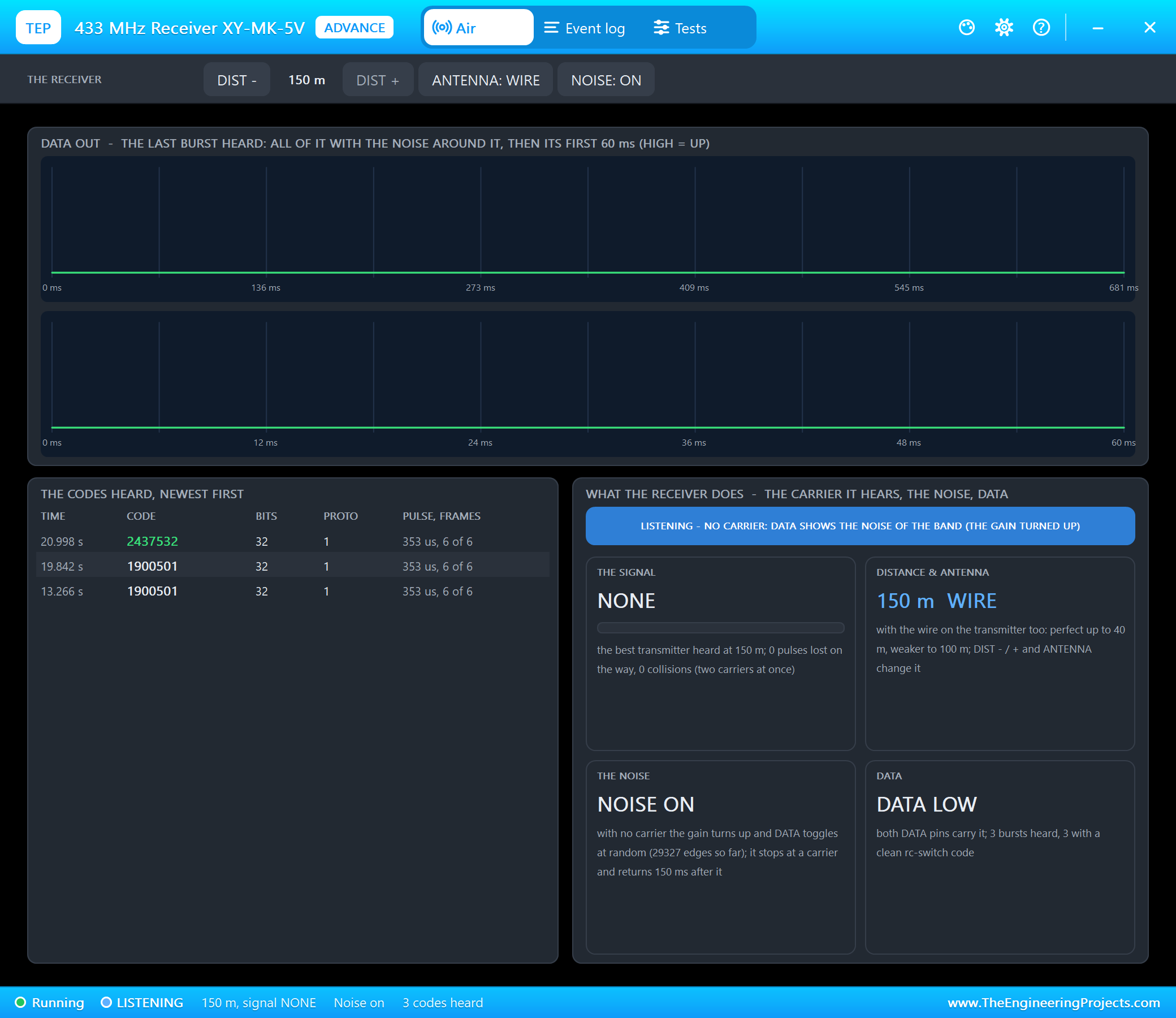
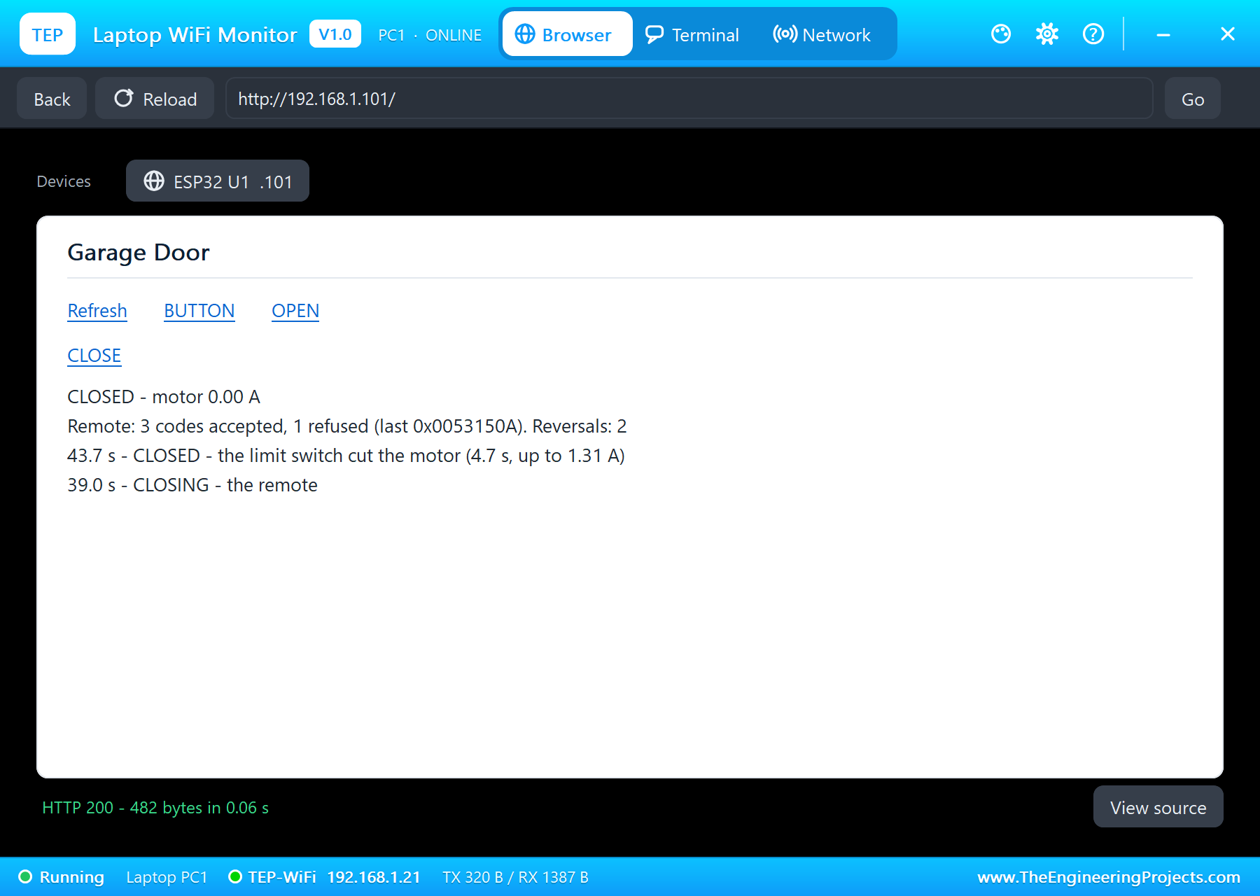
Finally the receiver goes 150 m away on its pop-up: far beyond the 433 MHz link's reach. The remote is pressed twice: "BUTTON: code 0x00374A1F (counter 3)" at 33.5 s and "code 0x004178D0 (counter 4)" at 35.8 s. The opener hears nothing; its receiver's pop-up shows signal NONE and still only the first three codes. Back at 10 m, the next press is counter 5, two ahead of what the opener expects, but inside the window of 16: at 39.0 s, "code 0x0053150A accepted: counter 5 (2 presses missed)", and the door closes. At 43.7 s it is down: "CLOSED - the limit switch cut the motor (4.7 s, up to 1.31 A)" - closing takes more current than opening, because now the motor lifts against the door's weight on the rod.
| What | Result |
|---|---|
| Counter 1 | accepted; opened in 4.4 s, up to 0.78 A; the start peak 9.6 A, ignored |
| REPLAY of counter 1 | refused: used before (a replay) |
| Counter 2 + the beam | closing, the beam broken at 10 cm: opened again |
| 1000 N while closing | an obstacle at 3.00 A: opened again |
| 150 m | counters 3 and 4 never arrived |
| Counter 5 at 10 m | accepted, 2 presses missed; closed in 4.7 s, up to 1.31 A |
| Simulation | 46 s of simulation; 3 codes accepted, 1 refused, 2 reversals |
Download the Project Files
Click the button below to download ESP32-Garage-Door-Opener-433MHz-Rolling-Code-Proteus-Simulation-v1.0.zip (about 5.0 MB, without the source code of the models):
433 MHz Rolling-Code Garage Door Opener on ESP32 - Proteus Simulation V1.0- Proteus Simulation: ESP32-Garage-Door-Opener.pdsprj, both HEX files and copies of the models.
- Arduino Code: ESP32_Garage_Opener and ESP32_Garage_Remote, the two sketches.
- Proteus Library Files: the LIB files of the ESP32 DevKit V1, the 433 MHz modules, the BTS7960, the linear actuator, the FC-51, the SMD LED and resistor, the push button and the two WiFi Monitors.
- Proteus Model Files: the DLL models.
- README.txt: the installation steps, the properties, the test results and the links to every library post.
No Proteus yet? Read How to Download and Install Proteus 7 and 8. New to libraries? Follow How to Install a New Library in Proteus.
How to Install the Project Files
- Close Proteus and extract the whole zip file, for example to your Desktop.
- Copy the files from Proteus Library Files into the LIBRARY folder of Proteus.
- Copy the files from Proteus Model Files into the MODELS folder.
- Start Proteus and open the project from the Proteus Simulation folder.
Changing the Code
Both sketches compile in the Arduino IDE with our TEP Boards for Proteus package: install rc-switch from the Library Manager, export the compiled binary of each sketch and set U1's or U4's PROGRAM property to the new file. Change SECRET in both sketches to pair your own remote; the window, the current thresholds and the inrush time are at the top of the opener's sketch.
Ideas to Extend the Project
- Keep the counter in the ESP32's flash (Preferences) on both sides, so a power cut does not reset it.
- Pair more remotes, each with its own ID and counter, and a learn button on the opener.
- Add the two-press resynchronisation for remotes pressed more than 16 times out of range.
- Replace the teaching check with AES from mbedTLS, which the ESP32 has built in.
- Close the door by itself after a few minutes open, if the beam is clear.
- Send a notification to a phone when the door opens, over MQTT or Telegram.
From Simulation to Real Hardware
- Antennas: a 17.3 cm wire on both modules, a quarter of the 433 MHz wavelength, gives the range a garage needs.
- Check your band: 433.92 MHz is licence-free in most of the world, with power and duty-cycle limits; in some countries remotes use 315 MHz instead.
- A real door: use the opener's motor and its own limit switches, a proper photo-eye pair, and set the obstacle current from a test with the real door.
- IS readings: add a small capacitor across the 680 ohm and average several readings; the start-up inrush is several times the running current.
- Safety first: a real garage door can injure; test the reversal with a solid object before anyone relies on it.
Troubleshooting
- Nothing is received: DATA must be on D27 at both ends, and the receiver within range on its pop-up.
- "The check does not match": SECRET must be the same in both sketches.
- "Too far ahead": the remote was pressed more than 16 times out of range; restart the opener or widen WINDOW.
- The door never stops at its ends: L_IS and R_IS must reach D34 and D35 with 680 ohm to GND.
- Obstacles are not found: lower JAM_A, or put more load on the rod in the simulation.
Limitations of the Simulation
- Both boards are on one sheet; the distance between the radios is the setting on the receiver's pop-up, and the noise is the model's.
- The door is a 50 mm actuator: a scale model of a real door's drive, not the door itself.
- The obstacle is a load set on the actuator's pop-up, and the beam is broken from the FC-51's pop-up.
- The network to the laptop and the phone is simulated inside Proteus.
- ESP32 is a product of Espressif Systems and the BTS7960 a driver of Infineon; the rolling code here is a teaching scheme, not KeeLoq or any product's code; this project is not made or endorsed by them or by Labcenter.
So, that was all about the 433 MHz Rolling-Code Garage Door Opener on ESP32 (Proteus Simulation). I hope it helps you understand how a 433 MHz remote talks, why a rolling code defeats a code grabber, how a motor driver's current sense tells you what the motor is doing, and why a door must reverse on an obstacle, all tested in a simulation before you go near a real garage door. More IoT projects with the ESP32 and the Raspberry Pi 5 are coming in this series. If you have any questions, ask in the comments and I will help you out. Till the next tutorial, take care and have fun!