Hello friends! In this tutorial, we will install the Arduino Library for Proteus and use it to simulate a small Arduino circuit. This package brings several classic Arduino board components together, so you can choose a board that matches your project without installing each original library separately.
Arduino Library for Proteus
Latest version: Arduino Library for Proteus V4.0 (October 2026): six boards with working LEDs, a RESET button and a built-in serial monitor
Earlier versions: V3.0 (2023) · V2.0 (2021) · V1.0 (2015, this tutorial)
One board only? UNO · Mega 2560 · Mega 1280 · Nano · Pro Mini · Mini (V4.0)
Helping Tools
- Serial Monitor Advance: a serial terminal window for the UART of your board
- Serial Monitor Expert: the serial monitor with extra debugging tools
- LCD Library for Proteus V3.0: 16x2, 20x4 and I2C LCDs to show your readings
We will begin with the included boards, then install the library and prepare a compiled program. Our first example uses an Arduino UNO and an LED. After that, we will discuss how to move the same source code to another board without overlooking processor, clock or pin differences.
The original download, screenshots and demonstration video remain attached. This is the V1.0 tutorial; newer versions are linked below. The goal is to understand the complete workflow, including what a board library provides and what still depends on the simulator's processor and peripheral support.

What Is Included in This Arduino Library?
The combined library contains six classic board components: UNO, Mega 2560, Mega 1280, Nano, Mini and Pro Mini. These boards do not all use the same microcontroller. Their drawings can look similar while their available memory, interfaces and compiler targets differ.
| Board | Processor family represented | Useful reason to choose it |
|---|---|---|
| Arduino UNO | ATmega328P | A familiar starting point for simple circuits and introductory lessons |
| Arduino Mega 2560 | ATmega2560 | More I/O, program space and hardware serial interfaces |
| Arduino Mega 1280 | ATmega1280 | Reproducing projects intended for the earlier Mega board |
| Arduino Nano | Classic ATmega328-family board | A compact breadboard-oriented project layout |
| Arduino Mini | Classic AVR Mini variant | Projects using that board's particular connections |
| Arduino Pro Mini | Classic AVR Pro Mini variant | Compact projects with an external programming interface |
Confirm the exact device and clock in the component you place. Classic Mini and Pro Mini boards have existed in different processor or voltage variants. The board label is the beginning of target selection, not a substitute for checking the component properties and matching IDE option.
The Mega 1280 and Mega 2560 are not interchangeable processors merely because their boards look alike. Compile for the intended target. The official Mega 2560 reference describes its ATmega2560, 54 digital I/O pins, 16 analog inputs and four UARTs, which explains why it can suit projects with several peripheral connections.
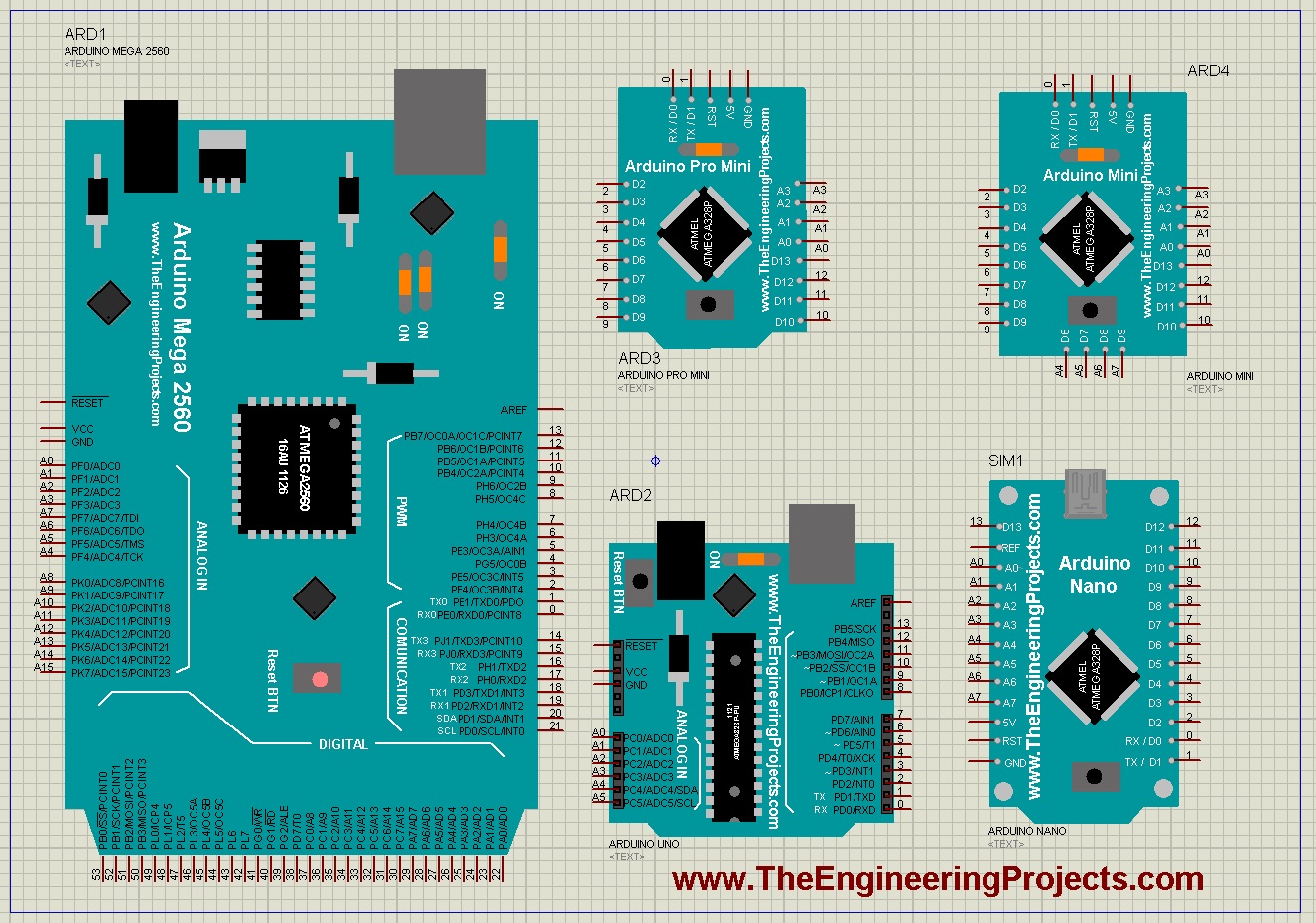
The historical group image does not show every included board separately. Use the component picker and the package's device names to identify the actual selection rather than inferring the complete contents from that illustration.
Original and Newer Library Releases
For the newer combined release, see Arduino Library for Proteus V4.0. Its guide covers the six boards with working LEDs, reset controls and built-in serial monitors. Earlier combined releases are documented as V3.0 and V2.0.
Keep the files from a chosen release together. Installing one version's library file with another version's support files can produce confusing errors. The original package described here should be evaluated using its own features, not the user interface shown in a newer tutorial.
Download and Install the Library
Download the original combined archive below. Its stored attachment uses a RAR archive, so extract it with a tool that supports that format. Do not simply rename its extension to ZIP.
Arduino Library for ProteusThe original installation uses ArduinoTEP.LIB and ArduinoTEP.IDX. These are Proteus library files. They belong in the library location used by Proteus, whereas Arduino IDE libraries contain source code and are installed through a different workflow.
- Close Proteus before copying the library files.
- Extract the downloaded archive into a working directory.
- Locate the LIB and IDX files in the extracted contents.
- Find the library directory used by your Proteus installation.
- Copy the matching file pair into that directory.
- Restart Proteus and open the component picker.
- Search for ArduinoTEP, then select the board needed for your circuit.
Do not assume that a Library folder inside an arbitrary program directory is the one your installation searches. Check the configured paths or follow the Proteus library-installation guide. Preserve a known working release before replacing it in an existing project.
If you installed several original board-specific packages previously, the search results may contain multiple related components. Select the intended library entry and record its release with your project. A board already placed on a schematic may retain its existing definition; copying a new file does not necessarily rebuild that placed instance.
What Installation Does Not Guarantee
A component appearing in the picker confirms that its library information was found. Running its firmware also requires an appropriate processor simulation model and any supporting peripheral models. A symbol with the correct artwork is not by itself a complete executable simulation.
Use a properly licensed Proteus configuration that supports the intended processor. If the simulation log reports a missing model, investigate that specific requirement. Reinstalling the Arduino IDE or changing the sketch's LED pin will not fix a missing processor simulation capability.
Prepare Firmware for the Selected Board
Arduino source code normally lives in an .ino sketch, while the AVR simulation loads a compiled program such as an Intel HEX file. Compilation translates the code for a particular processor and links the Arduino core functions and any required source libraries.
Select the board before building. For the first example, choose Arduino UNO in the Arduino AVR Boards platform. The official Arduino AVR board definitions show why this matters: board selections provide processor, clock and variant settings to the build process.
Compile the sketch and export the compiled binary using your IDE's export command. For direct loading into this simulation, use the ordinary application HEX unless the chosen model documents a different requirement. A separate with_bootloader image is intended for a different programming situation and should not be selected only because its filename looks more complete.
Keep the exported file alongside the schematic in a recognizable folder. A temporary build path can change between sessions, while a manually copied file can become outdated if you forget to replace it after editing the sketch. Establish one clear place for the executable you intend to simulate.
Build an Arduino UNO LED Test
Place the UNO component and connect D13 through a resistor to the anode of a red LED. Connect the cathode to ground. Use the board's documented power arrangement and a common ground for the circuit.
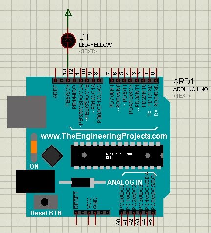
An external LED makes the test independent of whether the original board graphic animates its onboard indicator. It also lets you follow the complete current path. The resistor can be placed on either side of the LED as long as it remains in series.
For a simple estimate, assume 5 V at the output, a 2 V LED drop and a target current of 5 mA. The required resistance is (5 - 2) / 0.005 = 600 ohms. A 680-ohm resistor gives approximately 4.4 mA under these assumptions. Check actual output and LED characteristics when moving to hardware.
const byte ledPin = 13;
void setup() {
  pinMode(ledPin, OUTPUT);
  digitalWrite(ledPin, LOW);
}
void loop() {
  digitalWrite(ledPin, HIGH);
  delay(500);
  digitalWrite(ledPin, LOW);
  delay(500);
}
Double-click the UNO model, set Program File to the exported HEX and confirm its 16 MHz clock. Start the simulation. The expected waveform is high for half a second and low for half a second, giving a one-second period, 1 Hz frequency and 50 percent duty cycle.
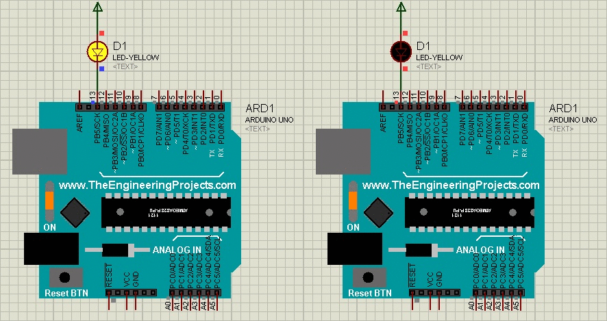
The animation is retained from the original demonstration. It illustrates the intended result; it is not a new execution report for every installed Proteus version. If the observed result differs, compare the actual schematic, compiled target and model properties before changing the example.
Move a Sketch Between Boards Correctly
Source-code portability and binary compatibility are different questions. A sketch using standard Arduino functions may compile for several boards, but the executable must still target the processor in your simulation. Do not load an ATmega328P image into a Mega model and expect the board library to translate it.
When changing boards, first update the IDE target and clock option, then rebuild. Next check every connection by its Arduino pin label and peripheral function. The physical position of a pin on one drawing does not identify the corresponding pin on another board.
| Item to review | Why it matters |
|---|---|
| Processor selection | Instruction target, registers and memory layout must match |
| Clock selection | Delays, UART baud and timer behavior depend on it |
| Peripheral pins | I2C and SPI appear at different header locations across boards |
| Serial port object | A Mega can use additional hardware UARTs that a classic UNO does not have |
| Logic voltage | External devices must tolerate the actual signal levels |
| Memory usage | A sketch that fits one processor can exceed another's resources |
For example, classic UNO I2C uses A4 for SDA and A5 for SCL, while Mega boards expose the corresponding bus through different Arduino pin assignments. Replacing the board graphic without checking the bus wiring can leave a correctly compiled program communicating with no connected device.
Likewise, a Pro Mini may use an 8 MHz configuration rather than the UNO's 16 MHz setting. Code built for 16 MHz and run at 8 MHz takes roughly twice as long for clock-dependent operations. If blinking and serial communication both behave incorrectly after a board change, inspect this mismatch first.
Keep a Small Board Test
Save the working LED example separately from the main project. For each board variant, compile it with that board's settings and check the expected timing. This provides a known starting point before you introduce a sensor library, communication protocol or larger application.
Write down the intended board, processor, clock and HEX path in the project notes. When you return to the project later, those four details are more useful than a filename such as final2.hex that does not identify its target.
Add Sensors and Communication in Stages
Once the board test runs, add a single peripheral. Establish its power and signal interface before adding application logic. A digital sensor model may use an interactive test input, a fixed stimulus or a register interface; follow that model's documentation rather than assuming its artwork reproduces every physical behavior.
For I2C, check the sensor address, SDA/SCL connections and pull-up arrangement. Two devices with the same fixed address cannot be independently selected on one bus without an additional arrangement. A successful scan confirms an address response, not necessarily correct measurement conversion or unit scaling.
For UART, connect transmit to receive in each direction and configure the same baud rate and framing at both ends. A simulated UART terminal and a physical computer serial port are separate interfaces. Do not assume the IDE Serial Monitor automatically connects to the board inside Proteus.
For SPI, check clock polarity, clock phase, bit order and chip selection as well as the shared data lines. A wrong chip-select connection can look like a software-library failure even when the compiled program is running correctly.
Our related models include GPS, XBee, ultrasonic sensing, PIR sensing, Bluetooth and flame sensing. Each requires its own model-specific setup.
Separate Electrical Tests from Application Tests
Consider a motion-controlled lamp. First establish that the sensor's simulated output changes. Next confirm the Arduino reads the assigned pin. Then check the program's decision and delay logic. Finally, test the output driver. Combining all four steps at once makes an unexpected result much harder to explain.
Use low-voltage indicators while developing control logic. A real relay, motor or high-power load needs a suitable driver and supply arrangement. The Arduino board model does not make a direct microcontroller connection suitable for every load shown on a schematic.
Read Simulation Results Carefully
Watch the simulated timebase when measuring delays. The host computer can run a complex simulation slower than real time, so wall-clock observation is not a reliable way to determine the firmware's interval. Use a logic analyzer, oscilloscope or the simulator's timing tools when the waveform matters.
For a digital output, record the high time, low time and repetition period. For serial data, inspect the transmitted bytes and line settings. For analog input, compare the applied voltage, reference voltage and expected ADC result. A visual change alone may not establish the numerical behavior required by the application.
As an illustrative ten-bit ADC calculation, an ideal converter with a 5 V reference has a nominal step of 5 / 1024, approximately 4.88 mV. A midscale input near 2.5 V should produce a code near 512. Real reference error, sensor error and converter characteristics still matter on physical hardware.
Do not infer battery life, radio range or regulator temperature from a processor-level simulation unless the specific models and measurements support that conclusion. Simulation is particularly useful for repeatable firmware inputs and logic behavior; physical implementation adds effects that may not be represented.
Troubleshooting Checklist
| Observed problem | Useful next step |
|---|---|
| No ArduinoTEP search results | Confirm extraction and the configured library directory, then restart Proteus |
| Several similar boards appear | Identify the intended library release and avoid mixing components accidentally |
| Missing simulation model error | Check the processor support required by that component |
| HEX file loads but nothing happens | Check target, power, reset state and a minimal output test |
| Timing differs by a fixed ratio | Compare the compiled clock with the model's clock |
| Peripheral fails after replacing the board | Review pin mapping, bus instance and voltage assumptions |
| New code seems ignored | Rebuild and confirm the selected HEX file's location and timestamp |
Change one suspected cause at a time. If you replace the model, rewire the sensor and modify the sketch together, a successful result will not tell you which change fixed the issue. Keep a short record of the configuration that first produces the expected output.
Library Review and Version-Specific Guides
The combined package is convenient for learning and for projects that use several classic Arduino board layouts. Its value is easier component selection and a consistent starting workflow. It does not promise that every Arduino product or every third-party peripheral is supported.
Individual V4.0 tutorials are available for UNO, Mega 2560, Mega 1280, Nano, Mini and Pro Mini. Choose the guide matching the component you actually install.
For further work, see the Genuino library, LCD Library V3.0, Serial Monitor Advance and Serial Monitor Expert. Add those components after your selected board passes its simple firmware test.
The original video remains below as a visual reference for the historical installation and demonstration. Menu appearance and library features can differ in newer versions.
Frequently Asked Questions
Does this archive include every Arduino board?
No. It contains the six classic board models listed in this tutorial. Boards such as Due, Yún and newer Nano variants need their own appropriate models and firmware targets.
Can one compiled HEX file run on all six boards?
No. Recompile for the selected processor and clock. Similar source code can be portable while the resulting machine-code image remains target-specific.
Do I install ArduinoTEP.LIB through Arduino Library Manager?
No. It is a Proteus library file. Arduino Library Manager installs source libraries used during compilation; the two installation paths are separate.
Why is Mega 1280 not shown separately in the old board image?
The historical illustration did not show it separately. It is listed as part of the package, but it remains a distinct processor target from Mega 2560 and must be selected accordingly.
Should I replace an existing working library immediately?
Keep the working project and its dependencies first. Test a newer release in a separate example, compare its documented features and then migrate deliberately rather than changing several dependencies at once.