Hello friends, I hope you all are doing great. Today, I am going to share the new Toroid Inductor Library for Proteus. Open a PC power supply, a solar charge controller, an amplifier or a motor drive and you will find a few doughnuts of copper wire: toroid inductors. A toroid is a coil wound round a ring, and that ring shape keeps its magnetic field almost entirely inside the core. It disturbs its neighbours very little, it picks up very little from them, and it packs a lot of inductance into a small, flat part. That is why the toroid is the classic choice for the power inductor of a buck converter and for the filters on a supply line.
Toroid Inductor Library for Proteus
Latest version: V1.0 (November 2026, this tutorial)
Other component libraries: C945 Transistor · PC817 Optocoupler · Relay Module · Resistor · 5 mm LED · Designer Colour LED · Push Button · Active Buzzer · Electrolytic Capacitor · Ceramic Capacitor · Tantalum Capacitor · Film Capacitor · 1N4007 Diode · Zener Diode · Schottky Diode · Supercapacitor · Photodiode · RGB LED · Bridge Rectifier · Flashing LED · Bi-Colour LED · SMD LED · Slide Switch · Toggle Switch · Rocker Switch · Micro Limit Switch · Emergency Stop Switch · SMD Resistor · Power Resistor · Resistor Network · Potentiometer · Trimmer Potentiometer · Slide Potentiometer · NTC Thermistor · DIP Switch · Fuse · Passive Buzzer · Mini Speaker · 7-Segment Display · LED Bar Graph · IR / UV LED · Small Transistors · TIP122 Darlington · N-MOSFET · P-MOSFET · PC817 Optocoupler · Filament Bulb · Power LED · Voltage Regulator · SCR and TRIAC · Inductor · Crystal
Helping Tools
- Serial Monitor Advance: a serial terminal window for the UART of your board
- Serial Monitor Expert: the serial monitor with extra debugging tools
- LCD Library for Proteus V3.0: 16x2, 20x4 and I2C LCDs to show your readings
Our library has a 100 µH powdered-iron toroid at true scale, 21.8 mm across and lying flat on the board, as the Bourns 2100LL-101-H-RC: 36 mΩ of winding resistance and a 4.3 A rating, at which its inductance has fallen to 46.2 µH. A powdered-iron core loses its inductance gradually instead of at a sudden knee, and the model follows that curve through both datasheet points. The model also has the winding's resistance and its heat, and the pop-up shows the field circling inside the ring, a scope of the current, and the inductance curve with the working point on it. The demo builds an Arduino buck converter that makes 5 V from 12 V, first at 1 A and then at 2 A.
NOTICE: Our team has put a lot of effort into these small parts: the bodies, the animation and the pop-ups are all our own design, and you get them free. Your feedback is the fuel that keeps us going, so please tell us what you think in the comments below or in the Toroid Inductor board of our forum. And if our free libraries help you, you can buy us a coffee. So, let's get started with the Toroid Inductor Library for Proteus:
What is a Toroid Inductor?
A toroid inductor is a coil of insulated copper wire wound through and around a ring-shaped magnetic core, the toroid. Like every inductor it stores energy in its magnetic field and resists changes of its current: V = L di/dt, the voltage across it equals its inductance times the rate of change of its current. What makes it special is the shape. In a straight coil or a drum core the field leaves one end, loops through the air and comes back at the other end; in a ring it simply goes round and round inside the core, which is a closed path with no ends.
| The toroid in the library | |
|---|---|
| Like | Bourns 2100LL-101-H-RC |
| Size | 21.8 mm across, lying flat; two leads 10.16 mm apart |
| Core | powdered iron |
| Inductance | 100 µH at no current |
| At its rated current | 46.2 µH at 4.3 A |
| Winding resistance | 36 mΩ |
| Rated current | 4.3 A |
| Made for | power converters and supply filters |
Why a Ring?
A closed magnetic path has three benefits. The first is containment: almost no field leaks out, so a toroid can sit next to a sensitive circuit or another inductor without coupling into it. The second is efficiency: every turn of wire links the whole flux, so fewer turns give the inductance, and fewer turns mean less wire and less resistance. The third is immunity: an outside field passes through the ring in both directions and cancels, so the toroid picks up little noise. The price is the winding: wire has to be threaded through the hole turn by turn, so toroids cost more to make than drum cores.
Powdered Iron and Soft Saturation
Every magnetic core can only carry so much flux. As the current rises the core fills up, its permeability falls and the inductance falls with it. In a solid ferrite core this happens late but suddenly: the inductance holds almost steady and then drops off a cliff. A powdered-iron core is different. It is made of tiny iron grains insulated from each other and pressed together, so its air gap is spread through the whole core. It saturates softly: the inductance starts to fall at a few hundred milliamps and keeps sliding down, with no cliff.
That changes how its datasheet reads. The 2100LL's rating of 4.3 A is not where it stops working: at 4.3 A it still has 46.2 µH, less than half of its no-current value. The model's curve runs through both of those points. It is 10 % down at 1.48 A, the point the model calls its saturation current, about 25 % down at 2.5 A and 54 % down at 4.3 A. A designer working with a powdered-iron toroid plans for the inductance at full load, not the value printed on it.
The Rated Current and the Winding Resistance
The other limit is heat. The 36 mΩ winding turns I² x R into heat: 36 mW at 1 A, 144 mW at 2 A, 666 mW at the 4.3 A rating, which warms the part about 40 °C. Copper's resistance rises 0.39 % for every degree, so a hot winding loses a little more. Thick wire on a big ring is why this toroid can carry many amps with a fraction of the resistance of a small drum core.
The Buck Converter
A buck converter makes a lower voltage from a higher one, with almost no loss in between. A switch connects the input to the switch node for part of each cycle, the duty cycle D. While it is on, the inductor has the input minus the output across it, 12 - 5 = 7 V, and its current ramps up. When the switch turns off, the inductor keeps its current flowing through a diode from ground; now the output, 5 V, is across it the other way and the current ramps down. The capacitor smooths what is left, and the output settles at D x Vin: 5 V from 12 V needs a duty of about 42 %, a little more to cover the losses.
The inductor's current is a triangle riding on the load current. Its peak-to-peak ripple is (Vin - Vout) x D x T / L: with 7 V, a 42 % duty, the 32 µs period of 31.25 kHz and 100 µH it is about 0.94 A. The average of the triangle is the load current, so at 1 A the current swings between about 0.5 and 1.5 A and never reaches zero: that is continuous mode. The inductance sits in the denominator, so when it falls the ripple grows: this is where a powdered-iron core shows itself.
That ripple current flows into the output capacitor, and the capacitor's own series resistance, its ESR, turns it into a ripple voltage: about ΔI x ESR. A general-purpose electrolytic of 0.5 Ω would put about 0.5 V of ripple on a 5 V output with 1 A of ripple current; a low-ESR type of 0.1 Ω brings it down to about 0.1 V. That is why switching supplies use capacitors rated for low ESR and high ripple current.
Switching the High Side
The switch of a buck converter sits between the 12 V supply and the inductor, on the high side. A P-MOSFET suits that place: it turns on when its gate is pulled below its source, and its source sits on 12 V. An Arduino pin can only reach 5 V, so a small NPN transistor does the work: when D9 is high, the 2N2222A pulls the gate down to ground and the IRF4905 turns on; when D9 is low, a 470 Ω resistor pulls the gate back up to 12 V and it turns off.
Where Toroids Are Used
Toroids are the power inductors of buck and boost converters, solar charge controllers and LED drivers. Wound with two windings they become common-mode chokes on mains inputs, and with two separate windings they become transformers for audio amplifiers and power supplies. Small powdered-iron toroids tune radio circuits, and large ones smooth the current of motor drives and inverters.
Features of the Toroid Inductor Library for Proteus
- The real look, at true scale: a dark powdered-iron ring, 21.8 mm across, wound all round with copper, its two leads 10.16 mm apart, with our small TEP signature.
- A warming winding: the copper darkens on the sheet as it heats.
- Soft saturation: the inductance falls gradually with the current, through 100 µH at no current and 46.2 µH at 4.3 A, as a powdered-iron core does.
- The winding's heat: its 36 mΩ turns current into heat, the rated current raises it 40 °C, and its resistance rises with it.
- Any value: type the inductance; AUTO scales the resistance and the currents from the 100 µH part, or type your own.
- A pop-up: the ring with the field circling inside its core, a scope of the current and the voltage, the inductance curve with the working point, eight live values, graphs, an event log and a check page.
- A complete package: about 3.5 MB with the library, our Arduino UNO V4.0, our MOSFETs, transistor, Schottky diode, capacitors and resistors and the demo, without the source code of the model.
The Toroid Inductor in Proteus
The device is TOROIDINDUCTORTEP in TEPTOROID.LIB, under Inductors, with the prefix L and the model TEPTOROID.DLL. Search TOROID in Pick Devices. The part lies flat, seen from above, with its pins 1 and 2 at the end of its two leads. An inductor has no polarity, so either way round is fine.
The Properties
| Property | What it does |
|---|---|
| Inductance (VALUE) | 100u, 47u, 220u or 1m; a bare number is in µH |
| Winding resistance (DCR) | in ohms, or AUTO to scale it from the 100 µH part |
| Current 10 % down (ISAT) | in amps, or AUTO: where the inductance has fallen 10 %; the curve keeps falling past it |
| Rated current (IRMS) | in amps, or AUTO: the current that warms the winding 40 °C |
Download Toroid Inductor Library for Proteus
Click the button below to download Toroid-Inductor-Library-for-Proteus-v1.0.zip (about 3.5 MB, without the source code of the models):
Toroid Inductor Library for Proteus V1.0- README.txt: installation, the demo, the buck converter's wiring, troubleshooting and the limits.
- Proteus Library Files:
TEPTOROID.LIB, our P-MOSFET, small transistor, N-MOSFET, Schottky diode, electrolytic capacitor, resistor and power resistor libraries, and ourArduinoV4TEP.LIB. - Proteus Model Files:
TEPTOROID.DLL, the DLLs of those parts andTEPARDUINO.DLL. - Arduino Code: the demo sketch.
- Proteus Simulation: the demo project, its HEX file and copies of the DLLs.
No Proteus yet? Read How to Download and Install Proteus 7 and 8. New to libraries? Follow How to Install a New Library in Proteus.
How to Install Toroid Inductor Library for Proteus
- Close Proteus and extract the whole zip file, for example to your Desktop.
- Copy the files from Proteus Library Files into the LIBRARY folder of Proteus.
- Copy the files from Proteus Model Files into the MODELS folder.
- Delete
TEPTOROID.IDXfrom the LIBRARY folder if it is there. - Start Proteus, press P and search for TOROID.
Demo: A Buck Converter, 12 V to 5 V
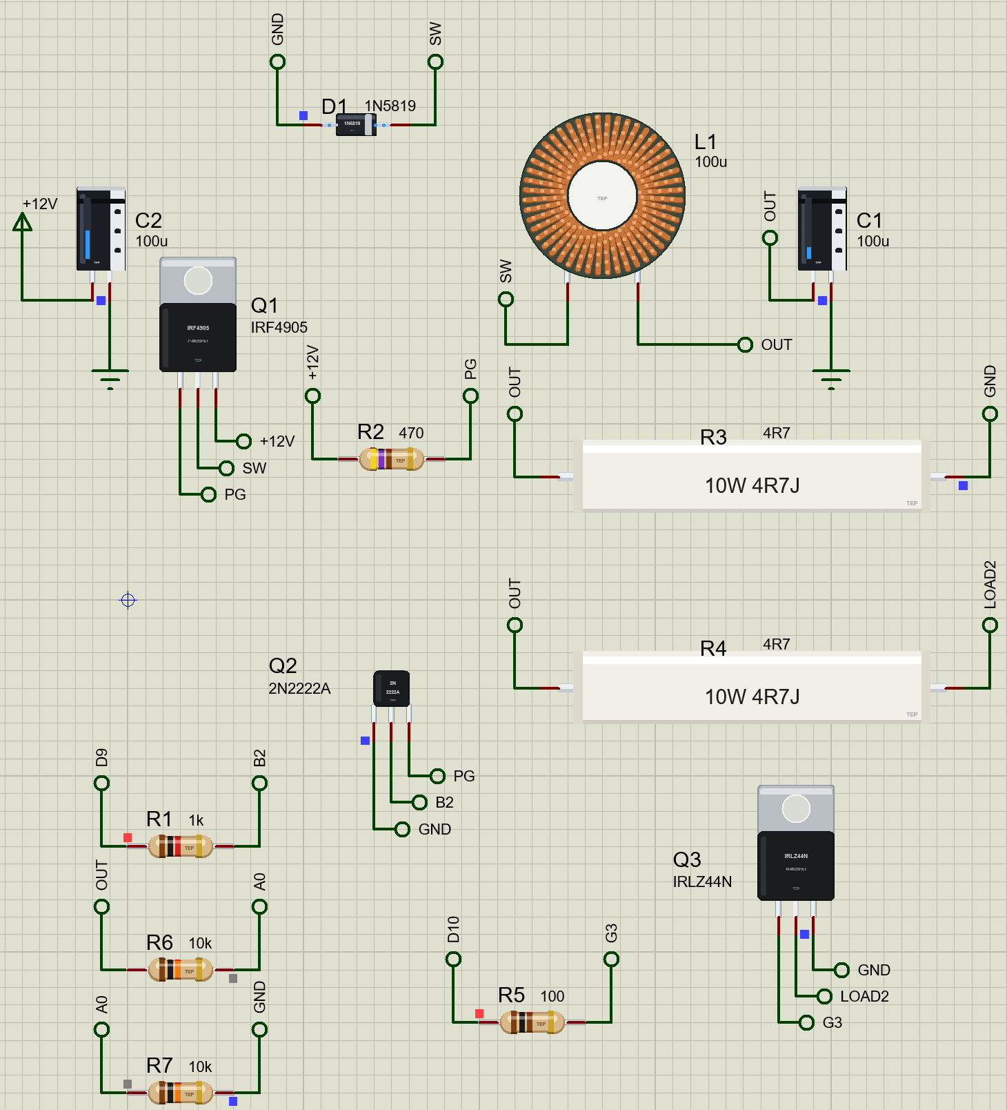
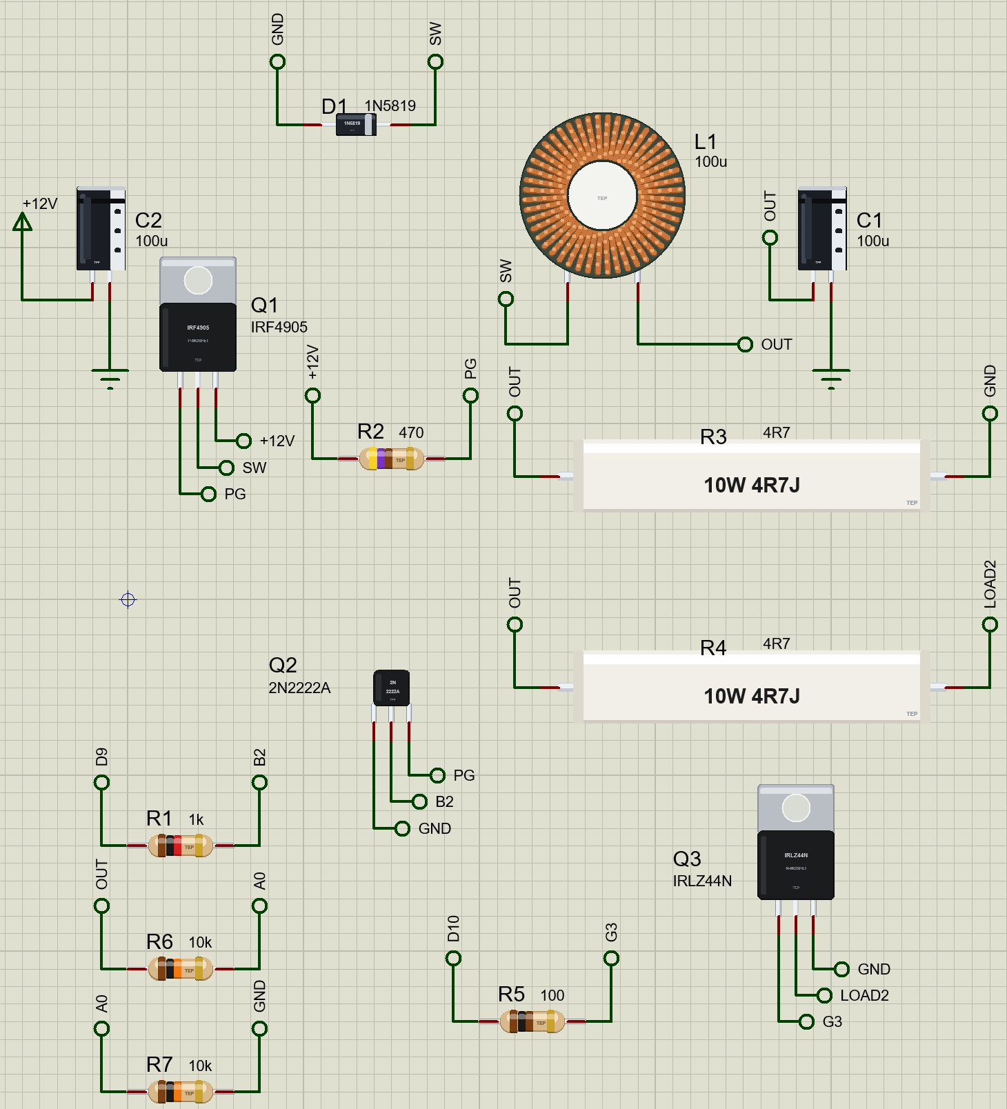
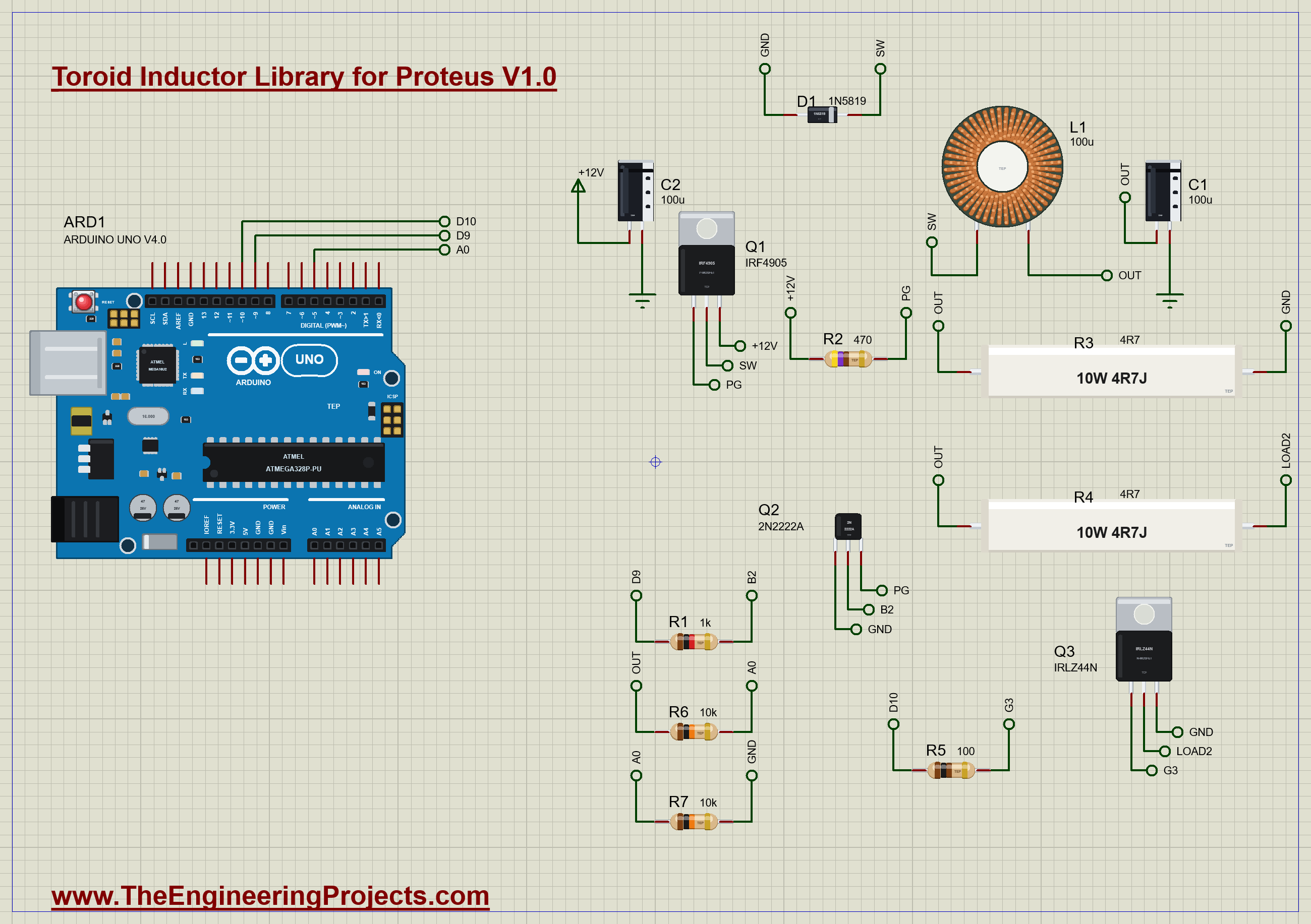
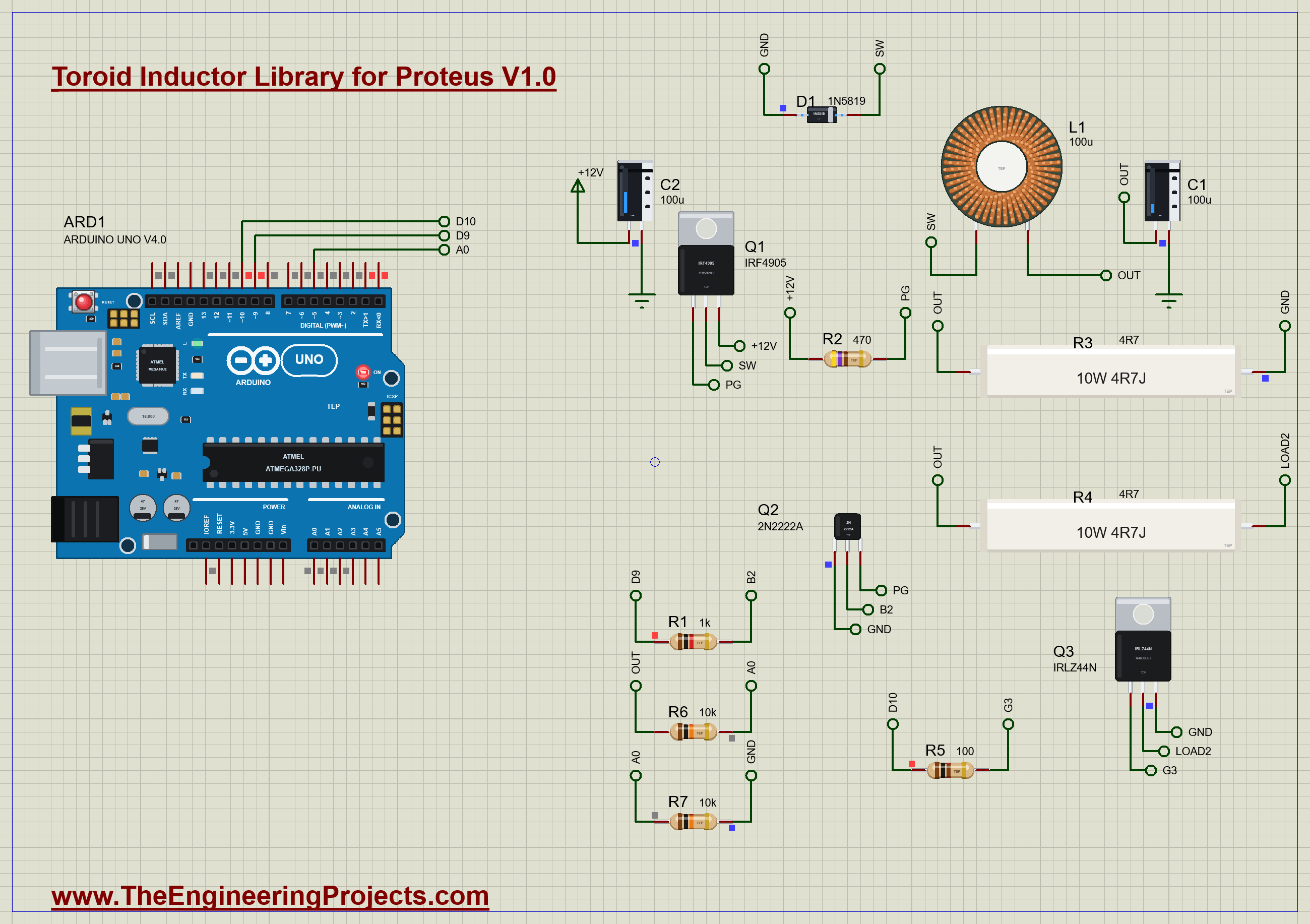
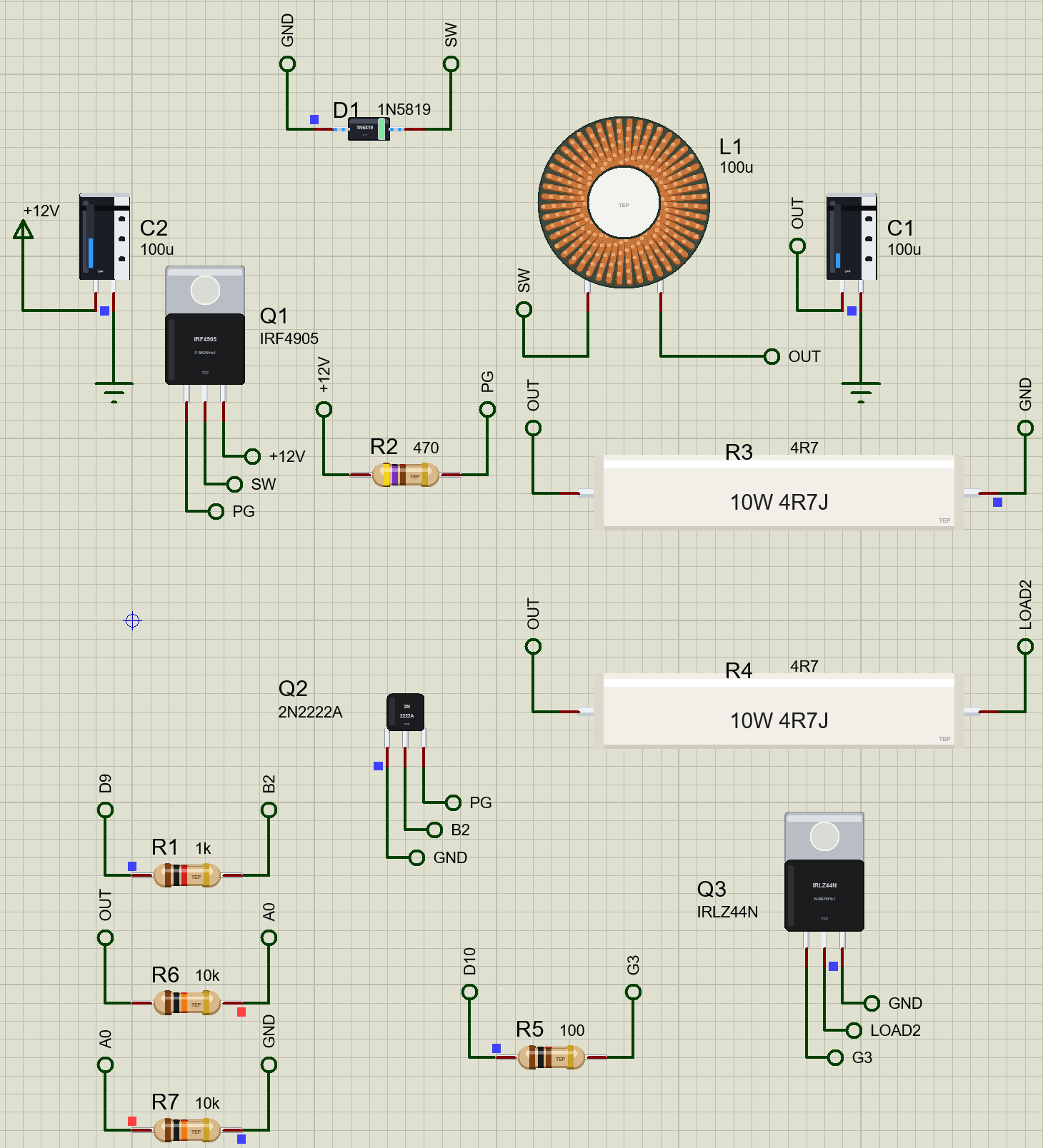
The converter runs from a 12 V supply with C2 (100 µF) on its input. Q1, an IRF4905 P-MOSFET, switches the 12 V onto the switch node SW; Q2, a 2N2222A, pulls its gate down from D9 through R1 (1k), and R2 (470 Ω) pulls it back up. D1, a 1N5819 Schottky diode, carries the current while Q1 is off. L1, the 100 µH toroid, and C1 (100 µF, a general-purpose electrolytic with 0.5 Ω of ESR) smooth SW into the output. R3, 4.7 Ω, is a 1 A load; at 0.8 s Q3, an IRLZ44N on D10, adds R4, another 4.7 Ω, for 2 A. R6 and R7 (10k / 10k) give A0 half of the output.
Open Toroid-Buck-ArduinoUnoV4.pdsprj. It runs on our Arduino UNO Library for Proteus V4.0, with its built-in monitor, the same window as our TEP Serial Monitor Advance for Proteus. The switch comes from our P-MOSFET Library for Proteus, its driver from our Small Transistors Library for Proteus, the load switch from our N-MOSFET Library for Proteus, the diode from our Schottky Diode Library for Proteus, the capacitors from our Electrolytic Capacitor Library for Proteus and the loads from our Power Resistor Library for Proteus.
| Part | Connection | Job |
|---|---|---|
| Q1 IRF4905, R2 470 | S to +12V, D to SW, G to PG; R2 from +12V to PG | the high-side switch |
| Q2 2N2222A, R1 1k | C to PG, E to GND; D9 - R1 - B | the gate driver |
| D1 1N5819 | A to GND, K to SW | the current path while Q1 is off |
| L1 toroid 100 µH, C1 100 µF | SW - L1 - OUT; C1 on OUT | the filter |
| R3 4R7 10 W | OUT to GND | the 1 A load |
| R4 4R7 10 W, Q3 IRLZ44N, R5 100 | OUT - R4 - Q3 to GND; D10 - R5 - gate | the second load, on at 0.8 s |
| R6 / R7 10k / 10k | OUT - A0 - GND | the feedback |
| C2 100 µF | on +12V | the input capacitor |
The Sketch
Timer1 drives the switch. A 9-bit fast PWM counts from 0 to 511 and gives 31.25 kHz on OC1A, which is D9:
  TCCR1A = _BV(WGM11);                                  // fast PWM, TOP = ICR1; OC1A joins D9 once the duty is above zero
  TCCR1B = _BV(WGM13) | _BV(WGM12) | _BV(CS10);         // no prescaler
  ICR1 = TOP;
C1's ESR leaves about half a volt of ripple on the output, so one reading of A0 lands anywhere on that ripple. The sketch takes eight readings, which spread over almost a millisecond and many switching cycles, and uses their mean:
    long sum = 0;
    for (byte k = 0; k < 8; k++) sum += analogRead(A0);
    const float v = sum / 8.0 * SCALE;
Every millisecond the sketch moves the duty one step up while the output is low and one step down while it is high. It keeps the duty under 94 % so the P-MOSFET's gate always gets a moment to recover:
    if (v < TARGET - 0.02 && duty < MAX_DUTY) duty++;
    else if (v > TARGET + 0.02 && duty > 0) duty--;
    OCR1A = duty;
A Trap: a Duty of Zero Is Not Off
The first version of this sketch connected D9 to the timer in setup() with the duty at zero, and the simulation stopped within a tenth of a second. The reason is a property of the timer's fast PWM mode: with OCR1A at zero, the pin still goes high for one timer clock at the start of every cycle. On its own such a spike is harmless, but here the 2N2222A amplifies it. It pulls the IRF4905's gate down hard, the MOSFET turns fully on, and then it turns off slowly through the 470 Ω pull-up, 31,250 times a second, before the converter has even started. A real board would do exactly the same. The fix is to leave D9 off the timer while the duty is zero:
    if (duty > 0) TCCR1A |= _BV(COM1A1);
    else TCCR1A &= ~_BV(COM1A1);
At 0.8 s it turns on the second load with D10 and says so, and every 250 ms it prints the output, the duty and the load.
Run the Demo
Press Run. The duty starts at zero and climbs a step every millisecond until the output reaches 5 V. Here is the complete circuit running:
The Toroid at 1 A
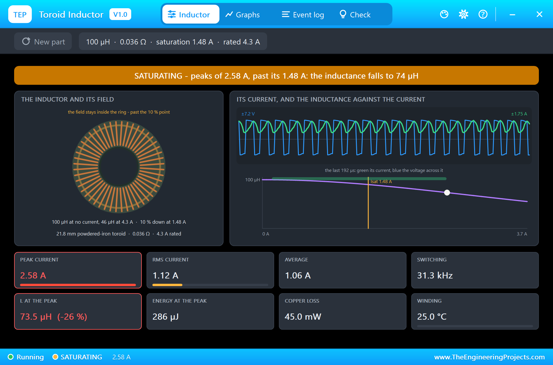
Click L1 at 0.6 s, with 1 A of load. The banner is amber: SATURATING, because the largest current of the last 50 ms, 2.58 A, is past the 1.48 A where the inductance is 10 % down; at that current the curve gives 73.5 µH, 26 % down. The scope tells the everyday story. The voltage across the toroid jumps to +7.2 V while Q1 is on (12 V in, 5 V out) and swings negative while D1 carries the current; the green current climbs in a straight ramp to about 1.7 A, falls back, and never touches zero, so the converter runs in continuous mode. The occasional larger peak comes from the regulation: every millisecond the sketch moves the duty, and the output filter answers with a slow swing on top of the ripple. The RMS current is 1.12 A, the average 1.06 A, the copper loses only 45.0 mW and the winding stays at 25.0 °C:
The Toroid at 2 A
At 0.8 s the second load comes on. Click L1 again at 1.5 s: the average current is now 2.11 A and the RMS 2.15 A, half of the 4.3 A rating. The peaks reach 3.00 A and the white dot has slid down the curve to 66.6 µH, 33 % below the value printed on the part. The energy stored at the peak is 368 µJ. The copper loss is 167 mW, about four times the 1 A figure for twice the current, as I² x R says, and the winding is still at 25.1 °C: its thermal time constant is minutes, not milliseconds:
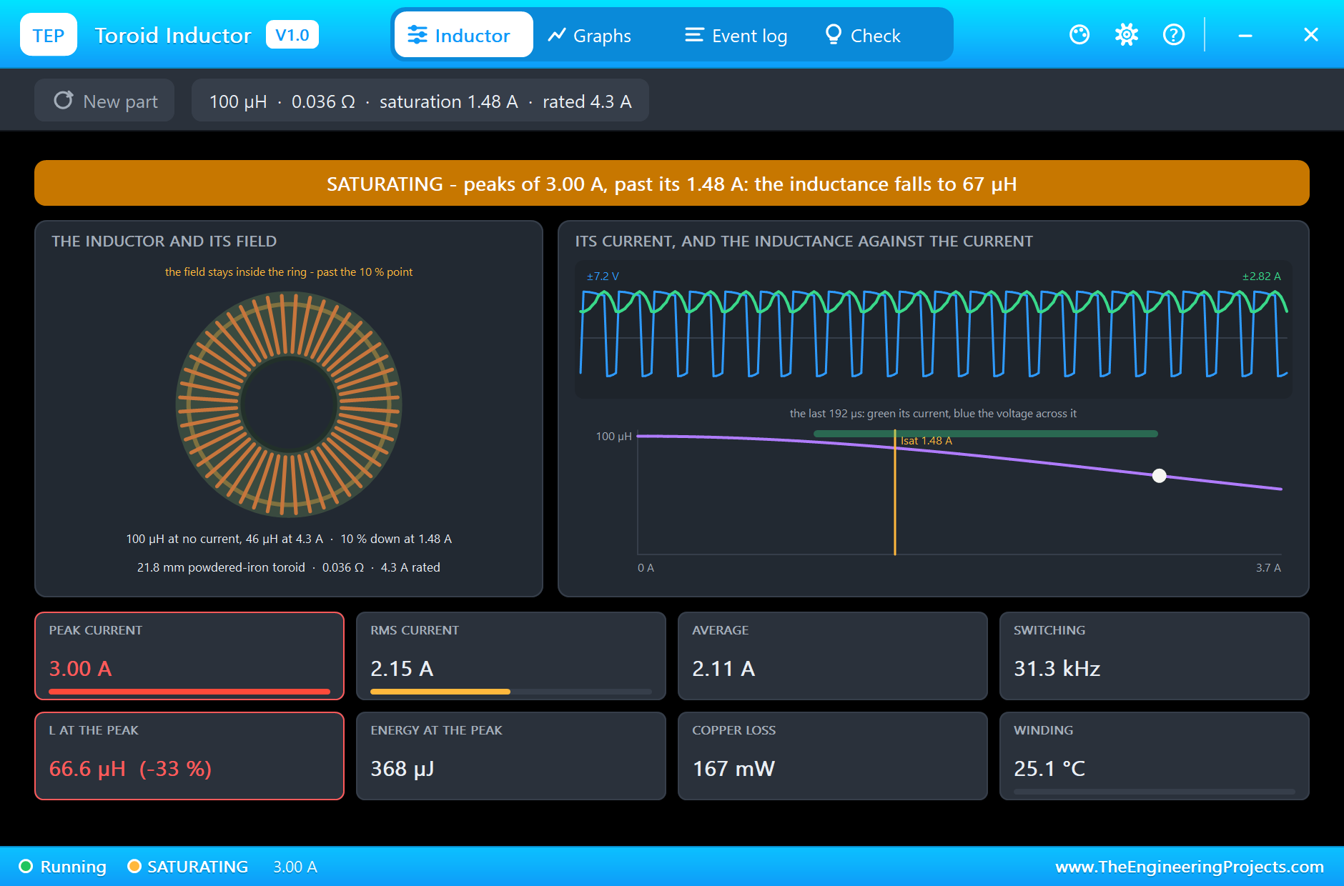
This is the lesson of the toroid. At half its rated current it is cool and comfortable, yet its inductance is already a third down at the peaks. That is not a fault: a powdered-iron core is meant to be used this way, and its rating is about heat, not inductance. What changes is the ripple: with less inductance the current ramps faster, so the peaks climb further. A designer picks the inductance from the curve at the full-load peak, here about 67 µH, not from the 100 µH printed on the part. And the field still circles inside the ring, so the parts around it hardly feel it.
The Monitor
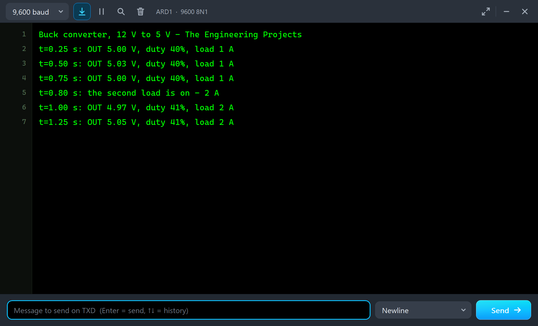
The monitor shows the regulation. At 1 A the output reads 5.00 to 5.03 V with a duty of 40 %. When the second load comes on at 0.80 s it dips to 4.97 V, the sketch raises the duty to 41 %, and by 1.25 s it reads 5.05 V. Notice the duty: 5 V from 12 V should need about 42 %, yet the sketch sets only 40 %. The P-MOSFET explains it. Q1 turns off only when R2 has charged its gate back up, which takes a microsecond or two, so the toroid sees the 12 V for about 45 % of each cycle, a little longer than the timer's pulse:
The Graphs, the Log and the Check Page
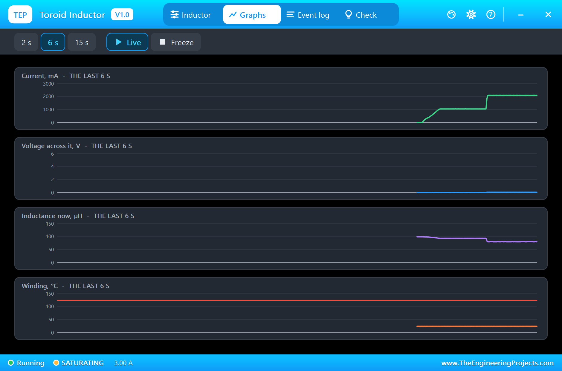
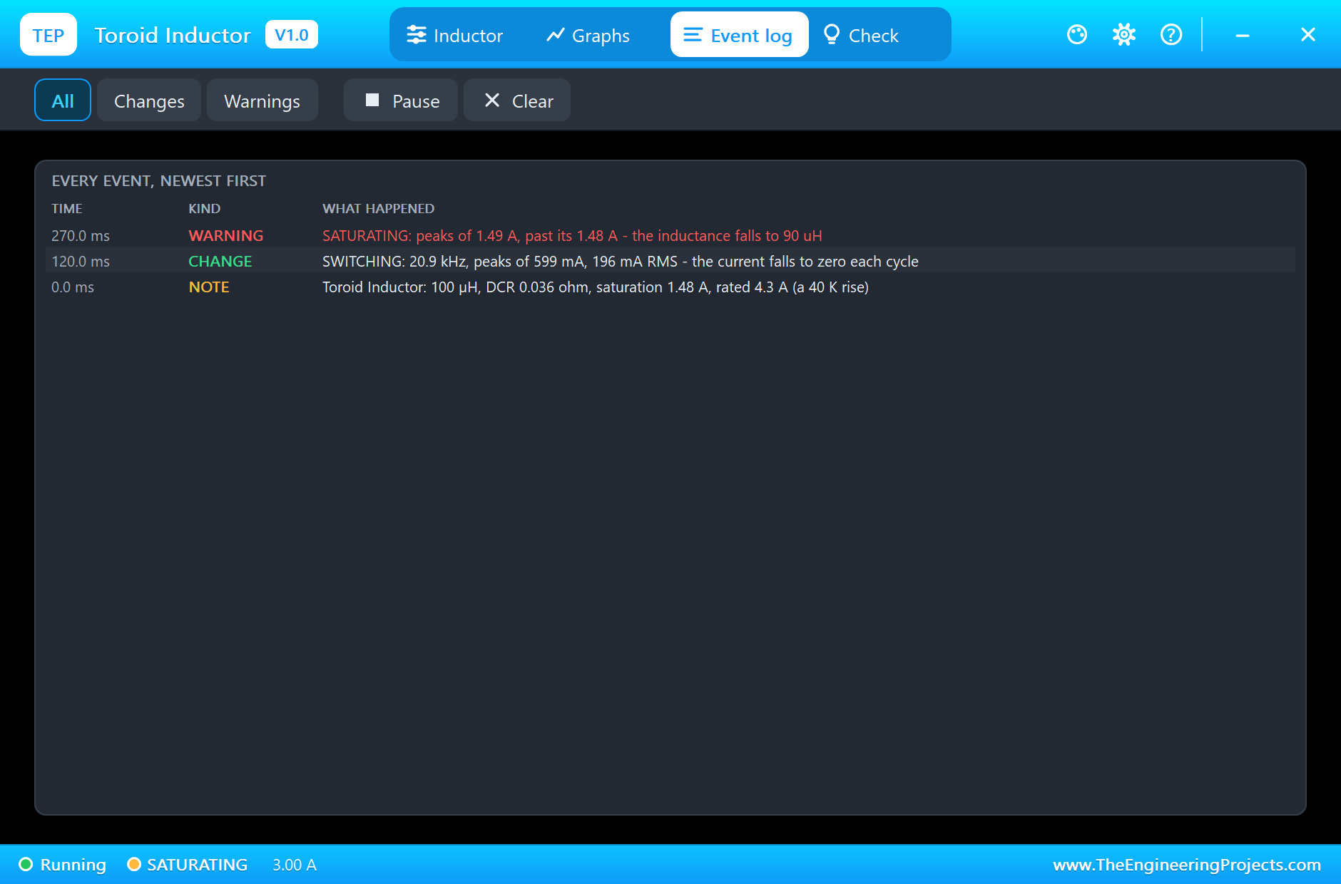
The Graphs page shows the whole run: the current climbing to 1 A as the converter starts, holding, and stepping to 2.1 A at 0.8 s; the inductance stepping down with it; the average voltage across the toroid at zero, as it must be, because in steady operation the volt-seconds of the ramp up and the ramp down cancel; and the winding flat at 25 °C, far under the red 125 °C line. The Event log tells the start: at 120 ms the toroid began switching in discontinuous mode, its current falling to zero each cycle while the output was still rising, and at 270 ms its peaks passed the 1.48 A point:
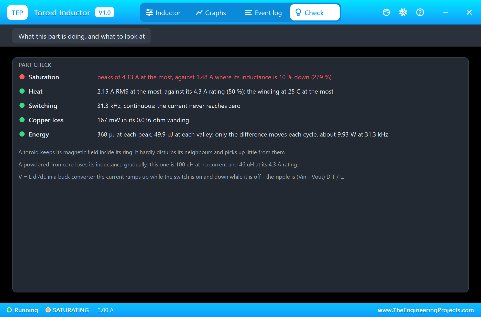
The Check page sums it up. Saturation is red: the largest peak of the whole run was 4.13 A, 279 % of the 10 % point but still under the 4.3 A rating, where this core keeps 46 µH. Heat is green: 2.15 A RMS is half the rating and the winding never left 25 °C. The converter runs in continuous mode and the copper loses 167 mW. The energy row shows why a buck's inductor works less hard than its peak suggests: of the 368 µJ stored at each peak, 49.9 µJ is still there at the valley, so only the difference moves each cycle:
Try It Yourself
- Set L1 to 47u: the ripple doubles and the peaks climb further down the curve.
- Set L1 to 220u: the triangles flatten, and AUTO raises the winding resistance with the turns.
- Change R3 to 2R2 so the first load takes over 2 A, and watch the inductance at the peak.
- Lower the target to 3.3 V in the sketch and watch the duty fall to about 30 %.
- Set C1's ESR to 0.1 Ω, a low-ESR type: the ripple shrinks, but L1's peaks grow, because the ESR was also damping the output filter's ringing.
Ideas to Extend the Demo
- Add a current-sense resistor and make a constant-current LED driver.
- Swap the toroid for the radial drum core of our Inductor Library for Proteus and compare the two at 2 A.
- Build a boost converter with the same toroid, an N-MOSFET and the Schottky diode.
- Measure the efficiency: input power against output power at both loads.
Your Own Sketches
The demo sketch is in the zip file, and you can change it in the Arduino IDE. New to Arduino? Start with our Arduino Tutorial for Beginners. Export the compiled binary, and set the UNO's PROGRAM property to the new file. Our guide on How to get the HEX file from Arduino shows you where the file ends up.
Things to Know Before Using a Real Toroid
- Read the curve, not the value: a powdered-iron toroid has much less than its printed inductance at full current.
- Check two currents: the peak against the inductance you need, the RMS against the rated current.
- Mount it firmly: a heavy toroid needs glue, a clip or a screw through the hole with an insulating washer; never a metal screw that makes a shorted turn.
- Keep the switching loop small: the switch, the diode and the input capacitor carry the fast edges.
- Powdered iron warms at high frequency: its core loss rises with the ripple and the frequency, on top of the copper loss.
Troubleshooting
- SATURATING: the peaks are past the 10 % point; for a powdered-iron toroid that is a gentle slope, but the ripple grows. Use a bigger part if the inductance falls too far.
- OVER RATING: the RMS current is past the rating; the winding heats.
- BURNT OPEN: the winding passed 180 °C; use New part and fix the current.
- The output will not rise: check the P-MOSFET's pins, the NPN's base resistor and the diode's direction.
- Timestep too small at the start: your sketch leaves the PWM pin on the timer at a duty of zero; it still pulses once a cycle.
- The part is not simulated:
TEPTOROID.DLLis missing from MODELS and from the project folder.
Limitations of the Simulation
- The core's losses at high frequency, the self-resonance and the winding's capacitance are not modelled.
- The values come from distributor listings of the Bourns part; the curve between its two points is the model's own smooth fit.
- A switching demo is slow to simulate: each second of the demo takes several minutes.
- Arduino is a name of Arduino; this library is not made or endorsed by Arduino or Labcenter.
- Tested in Proteus 8.5 in November 2026 (the demo as shipped). Proteus 7 is not supported.
So, that was all about the Toroid Inductor Library for Proteus. I hope it helps you see why a ring keeps its field to itself, how a powdered-iron core gives up its inductance gently, and what really happens inside a buck converter. If you have any questions, ask in the comments and I will help you out. Till the next tutorial, take care and have fun!