Hello friends, I hope you all are doing great. Today, I am going to share the new SCR and TRIAC Library for Proteus. Thyristors are the switches of the AC world: the part inside every light dimmer, the speed control of a drill or a fan, the heater control of a soldering station and the solid-state relay. They behave like no other transistor. A tiny pulse on the gate turns them on, and then they stay on by themselves, gate or no gate, until the current through them dies away. That one property is what makes them so useful on AC, and so puzzling the first time you meet them.
SCR and TRIAC Library for Proteus
Latest version: V1.0 (November 2026, this tutorial)
Other component libraries: C945 Transistor · PC817 Optocoupler · Relay Module · Resistor · 5 mm LED · Designer Colour LED · Push Button · Active Buzzer · Electrolytic Capacitor · Ceramic Capacitor · Tantalum Capacitor · Film Capacitor · 1N4007 Diode · Zener Diode · Schottky Diode · Supercapacitor · Photodiode · RGB LED · Bridge Rectifier · Flashing LED · Bi-Colour LED · SMD LED · Slide Switch · Toggle Switch · Rocker Switch · Micro Limit Switch · Emergency Stop Switch · SMD Resistor · Power Resistor · Resistor Network · Potentiometer · Trimmer Potentiometer · Slide Potentiometer · NTC Thermistor · DIP Switch · Fuse · Passive Buzzer · Mini Speaker · 7-Segment Display · LED Bar Graph · IR / UV LED · Small Transistors · TIP122 Darlington · N-MOSFET · P-MOSFET · PC817 Optocoupler · Filament Bulb · Power LED · Voltage Regulator · Inductor · Toroid Inductor · Crystal
Helping Tools
- Serial Monitor Advance: a serial terminal window for the UART of your board
- Serial Monitor Expert: the serial monitor with extra debugging tools
- LCD Library for Proteus V3.0: 16x2, 20x4 and I2C LCDs to show your readings
Our library has two thyristors at true scale in their TO-220 packages: the BT151 SCR (500 V, 12 A) and the BT136-600E triac (600 V, 4 A, the sensitive-gate version made to be driven from a microcontroller). The model has the gate junction, the latch with its gate trigger, latching and holding currents from the datasheets, the triac's four quadrants, the on-state voltage, and the heat. The pop-up shows the latch step by step for the SCR, and a small oscilloscope of the last two AC cycles with the firing angle for the triac. The demo builds an SCR latch on DC and a triac light dimmer on AC, timed by an Arduino from a PC817 zero-crossing detector.
NOTICE: Our team has put a lot of effort into these small parts: the bodies, the animation and the pop-ups are all our own design, and you get them free. Your feedback is the fuel that keeps us going, so please tell us what you think in the comments below or in the SCR and TRIAC board of our forum. And if our free libraries help you, you can buy us a coffee. So, let's get started with the SCR and TRIAC Library for Proteus:
What is a Thyristor?
A thyristor is a four-layer semiconductor, P-N-P-N, with three terminals. The easiest way to understand it is as two transistors wired into each other: a PNP and an NPN, each one's collector feeding the other one's base. As long as neither conducts, nothing happens and the device blocks the full voltage across it. Push a little current into the gate, the base of the NPN, and the NPN starts to conduct; that turns on the PNP, which feeds even more current into the NPN's base, and in a few microseconds both are fully on and holding each other on. That is a latch: the gate only starts it, and once it runs it keeps itself going.
| BT151-500R SCR | BT136-600E triac | |
|---|---|---|
| Pins (TO-220) | 1 K, 2 A, 3 G; the tab is A | 1 T1, 2 T2, 3 G; the tab is T2 |
| Blocking voltage | 500 V both ways | 600 V both ways |
| Current | 12 A RMS, 100 A surge | 4 A RMS, 25 A surge |
| Gate trigger current | 2 mA typical, 15 mA max | 2.5 / 4 / 5 / 11 mA typical in Q1 to Q4 |
| Latching current | 10 mA typical, 40 mA max | 2.5 to 10 mA typical |
| Holding current | 7 mA typical, 20 mA max | 2.2 mA typical, 15 mA max |
| On-state voltage | 1.4 V at 23 A | 1.4 V at 5 A |
| Junction to tab / to air | 1.3 / 60 °C/W | 3.0 / 60 °C/W |
The SCR
The SCR, silicon controlled rectifier, is the basic thyristor. Its terminals are the anode, the cathode and the gate. With the anode positive it blocks until a gate current of a few milliamps flows from the gate to the cathode; then it switches on and conducts from anode to cathode with a drop of about one volt. With the anode negative it blocks like a diode, whatever the gate does. In the TO-220 package of the BT151 the tab is the anode, so a heatsink on it is live.
Latching and Holding Current
Two small currents decide how an SCR behaves once fired. The latching current, IL, is the anode current the SCR needs before the gate can go away: if the gate pulse ends while less than IL flows, the regenerative action has not taken hold and the SCR drops out again. For the BT151 that is about 10 mA, and up to 40 mA for the worst parts. The holding current, IH, is the least current that keeps a latched SCR on: about 7 mA. A lamp that takes hundreds of milliamps latches at once; a load of a few milliamps may never latch at all. Both currents, and the gate trigger current, fall as the junction warms.
Turning an SCR Off
The gate cannot turn an ordinary SCR off. On DC there are three ways: break the circuit, briefly short the SCR so that its current drops under the holding current, or reverse the voltage across it. Shorting it for a moment with a transistor is called forced commutation, and it is what our demo does. On AC the problem solves itself: the current passes through zero a hundred times a second, and each time the SCR turns off. That is called natural commutation, and it is the reason thyristors are so at home on AC.
The TRIAC
A triac is, in effect, two SCRs back to back in one chip, with one gate. It conducts in both directions, so it can switch both halves of an AC wave. Its main terminals are T1 (or MT1) and T2 (MT2), and the gate is measured against T1. It can be fired with a positive or a negative gate current, whatever the polarity of T2, which gives four combinations called quadrants. Q1 is T2 positive with a positive gate, Q2 is T2 positive with a negative gate, Q3 is T2 negative with a negative gate and Q4 is T2 negative with a positive gate.
The quadrants are not equally sensitive. The BT136-600E needs about 2.5 mA in Q1, 4 mA in Q2 and 5 mA in Q3, but 11 mA in Q4, and up to 25 mA for the worst parts. A microcontroller that drives the gate with positive pulses uses Q1 in the positive half-cycles and Q4 in the negative ones, so its gate resistor must be sized for Q4. Opto-triac drivers and many triac circuits drive the gate negative instead, to stay in Q2 and Q3.
Phase Control
A triac turns off at every zero of its current. To keep a lamp on, it needs a new gate pulse in every half-cycle, and that is exactly what makes dimming possible. If the pulse comes right after the zero, the lamp gets nearly the whole half-cycle. If it comes later, the triac blocks for the first part and conducts only for the rest. The delay from the zero to the pulse is the firing angle, measured in degrees of the 180° half-cycle (10 ms at 50 Hz). For a resistive load the share of full power is 1 - α/π + sin(2α)/(2π):
| Delay after the zero (50 Hz) | Firing angle | Share of full power |
|---|---|---|
| 1 ms | 18° | about 99 % |
| 2 ms | 36° | about 95 % |
| 5 ms | 90° | 50 % |
| 8 ms | 144° | about 5 % |
| 9.5 ms | 171° | well under 1 % |
Zero-Crossing Detection
To fire at a set delay, the controller must know where the zeros are. A common way is an optocoupler: the AC drives its LED through a resistor, so the output transistor conducts in every positive half-cycle and the controller sees an edge at each zero. A diode across the LED carries the negative half-cycles. The LED needs about a volt before it lights, so the edges come a little after the zero on the way up and a little before it on the way down; at 12 V AC that is about a quarter of a millisecond, and a careful sketch corrects for it.
Heat and Inrush
A thyristor drops about a volt when it conducts, so it turns roughly one watt per amp into heat: 1.5 W for a 21 W lamp at 12 V. With about 60 °C/W from the junction to the air, that is too much for a bare TO-220 for long. Filament lamps add a second trap: a cold filament has about a tenth of its hot resistance, so the first half-cycles draw ten times the running current. The surge rating, ITSM, exists for exactly this.
Where They Are Used
Triacs dim lights, control the speed of universal motors in drills, mixers and fans, switch heaters, and form the output of most AC solid-state relays. SCRs rectify and control power in battery chargers and motor drives, fire camera flashes and ignition systems, latch alarms, and protect power supplies as crowbars that short the output when the voltage climbs too high. On the mains they are always driven through isolation, usually an opto-triac.
Features of the SCR and TRIAC Library for Proteus
- The real look, at true scale: the TO-220 body, the tab with its hole and three legs 2.54 mm apart, printed BT151 / 500R or BT136 / 600E, with our small TEP signature.
- A real latch: fired by the gate past IGT, latched past IL, held down to IH, with the datasheet values, falling as the junction warms.
- The triac's four quadrants: each with its own gate trigger and latching current.
- A real on-state: about a volt plus a series resistance, so the heat follows the current.
- Breakover: past its rated voltage by a quarter it fires with no gate, as the datasheet warns.
- The heat path: junction, tab and air, the heatsink a property: NONE, SMALL or LARGE.
- A pop-up for each part: the part and its glowing symbol, the latch with its currents (SCR) or a scope of the last two cycles with the firing angle and the quadrants (triac), eight live values, graphs, an event log and a check page.
- A complete package: about 2.9 MB with the library, our Arduino UNO V4.0, our bulbs, PC817, 1N4007, MOSFET and resistors and the demo, without the source code of the model.
The Thyristors in Proteus
The devices are SCRBT151TEP and TRIACBT136TEP in TEPTHYR.LIB, under Thyristors, SCRs and Triacs, with the prefix Q and the model TEPTHYR.DLL. Search BT1 in Pick Devices. Each is drawn from the front at true scale with its legs pointing down: the SCR's pins are K, A and G from left to right, the triac's T1, T2 and G.
The Properties
| Property | What it does |
|---|---|
| Part (VALUE) | the label: BT151 or BT136 |
| Heatsink | NONE (the bare tab, about 60 °C/W to the air in all), SMALL (15 °C/W from the tab) or LARGE (5 °C/W) |
Download SCR and TRIAC Library for Proteus
Click the button below to download SCR-and-TRIAC-Library-for-Proteus-v1.0.zip (about 2.9 MB, without the source code of the models):
SCR and TRIAC Library for Proteus V1.0- README.txt: installation, the demo, the wiring of both parts, the quadrants, troubleshooting and the limits.
- Proteus Library Files:
TEPTHYR.LIB, our resistor, N-MOSFET, bulb, optocoupler and diode libraries, and ourArduinoV4TEP.LIB. - Proteus Model Files:
TEPTHYR.DLL, the DLLs of those parts andTEPARDUINO.DLL. - Arduino Code: the demo sketch.
- Proteus Simulation: the demo project, its HEX file and copies of the DLLs.
No Proteus yet? Read How to Download and Install Proteus 7 and 8. New to libraries? Follow How to Install a New Library in Proteus.
How to Install SCR and TRIAC Library for Proteus
- Close Proteus and extract the whole zip file, for example to your Desktop.
- Copy the files from Proteus Library Files into the LIBRARY folder of Proteus.
- Copy the files from Proteus Model Files into the MODELS folder.
- Delete
TEPTHYR.IDXfrom the LIBRARY folder if it is there. - Start Proteus, press P and search for BT1.
Demo: An SCR Latch and a TRIAC Dimmer
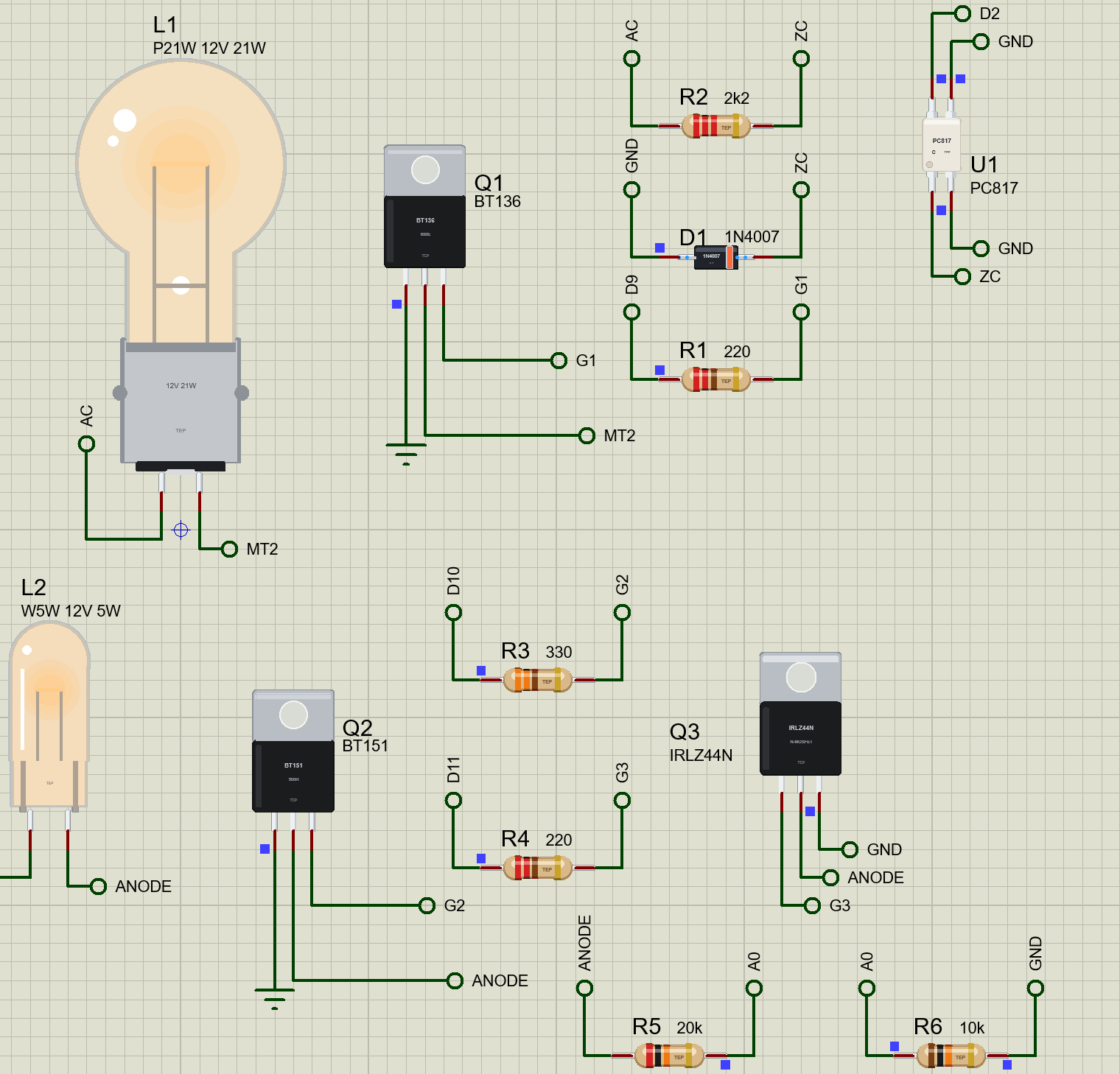
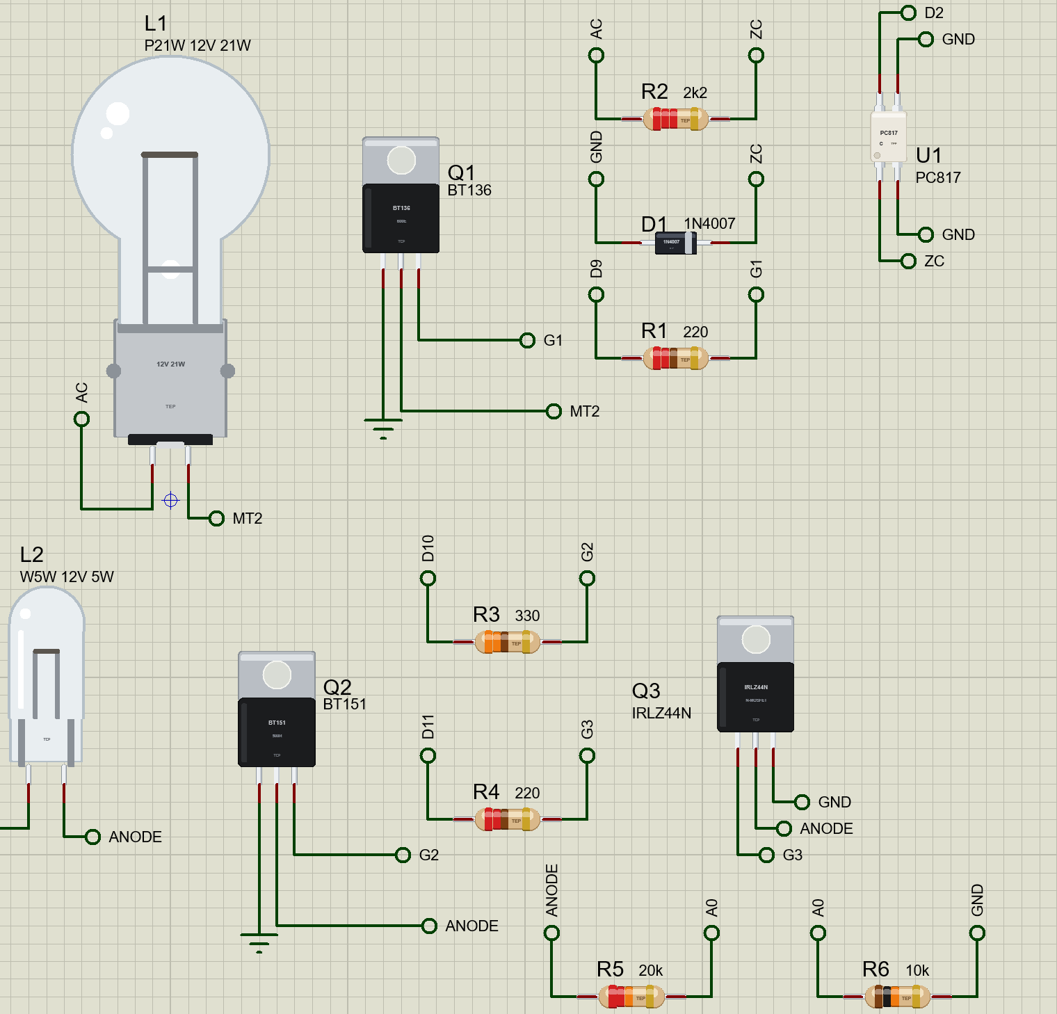
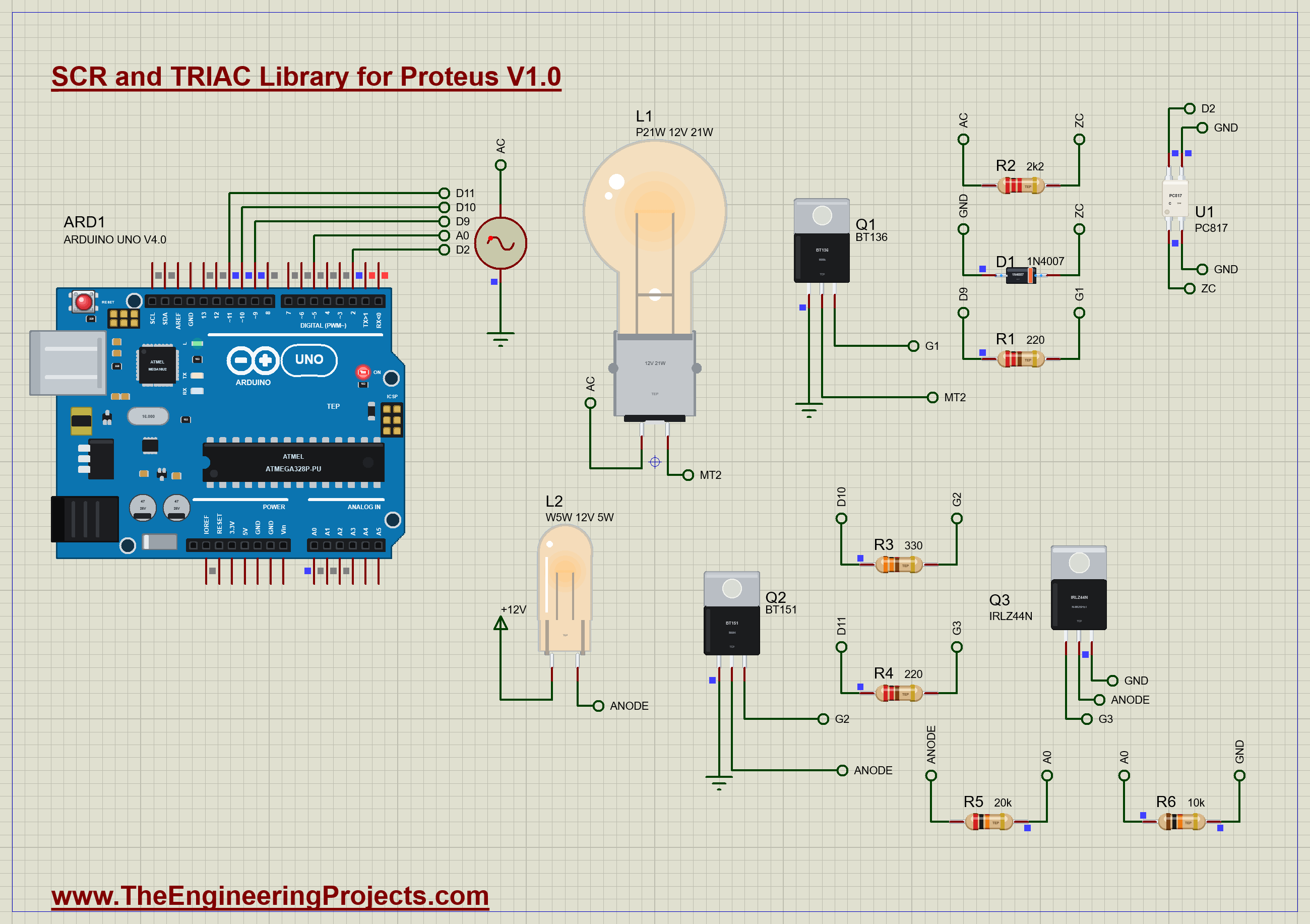
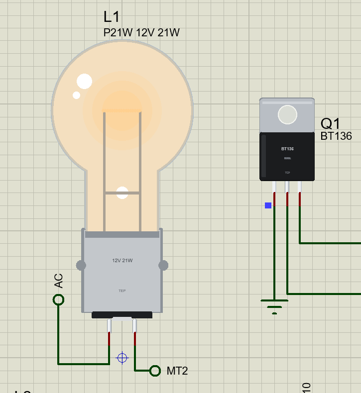
The sheet has two circuits. The dimmer: V1, Proteus's own AC source, gives 12 V RMS at 50 Hz to L1, a 12 V 21 W car bulb, through Q1, the BT136 triac. The Arduino fires Q1's gate from D9 through R1 (220 Ω). U1, a PC817, watches the AC through R2 (2.2k) with D1, a 1N4007, across its LED, and its output pulls D2 low in every positive half-cycle. The latch: L2, a 12 V 5 W bulb, runs from a 12 V DC supply through Q2, the BT151 SCR, fired from D10 through R3 (330 Ω). Q3, an IRLZ44N across the SCR, can short it from D11 through R4 (220 Ω), and R5 / R6 (20k / 10k) let A0 read a third of the SCR's anode voltage.
Open SCR-and-TRIAC-ArduinoUnoV4.pdsprj. It runs on our Arduino UNO Library for Proteus V4.0, with its built-in monitor, the same window as our TEP Serial Monitor Advance for Proteus. The bulbs come from our Filament Bulb Library for Proteus, the zero-crossing detector from our PC817 Optocoupler Library for Proteus and 1N4007 Diode Library for Proteus, and Q3 from our N-MOSFET Library for Proteus.
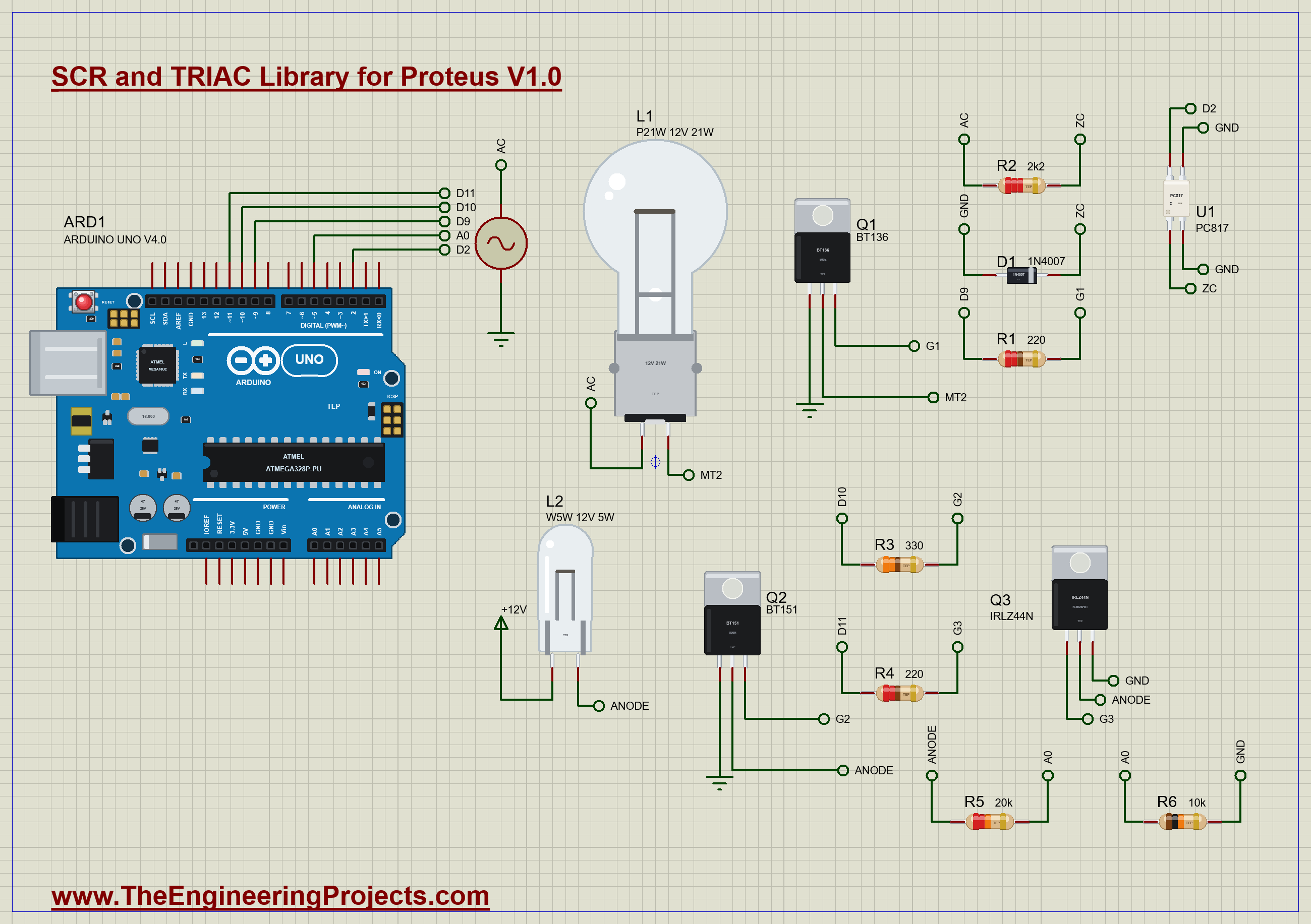
| Part | Connection | Job |
|---|---|---|
| V1, L1 P21W, Q1 BT136, R1 220 | AC - L1 - T2, T1 to GND, gate from D9 | the dimmer |
| R2 2k2, U1 PC817, D1 1N4007 | AC - R2 - LED, output to D2 | the zero-crossing detector |
| L2 W5W, Q2 BT151, R3 330 | +12V - L2 - A, K to GND, gate from D10 | the latch |
| Q3 IRLZ44N, R4 220 | across Q2, gate from D11 | turns the SCR off |
| R5 20k, R6 10k | anode - A0 - GND | reads the SCR |
The Sketch
An interrupt on D2 catches every edge from the PC817. Because the PC817 only sees the AC above about a volt, the true zero was a quarter of a millisecond before a falling edge and comes a quarter of a millisecond after a rising one:
void zero() {                  // an edge of D2: the zero was ZC_US before a fall, and comes ZC_US after a rise
  if (digitalRead(ZERO) == LOW) zeroAt = micros() - ZC_US;
  else zeroAt = micros() + ZC_US;
  zeroSeen = true;
}
The loop waits until the firing delay has passed since that zero and gives the triac's gate a 200 µs pulse. Nothing else in the loop waits, so the pulses stay on time; the SCR's steps are timed by the clock the same way:
    if ((long)(micros() - target) >= 0) {
      zeroSeen = false;
      pulse(TRIAC_GATE, 200);
    }
Run the Demo
The SCR Latches
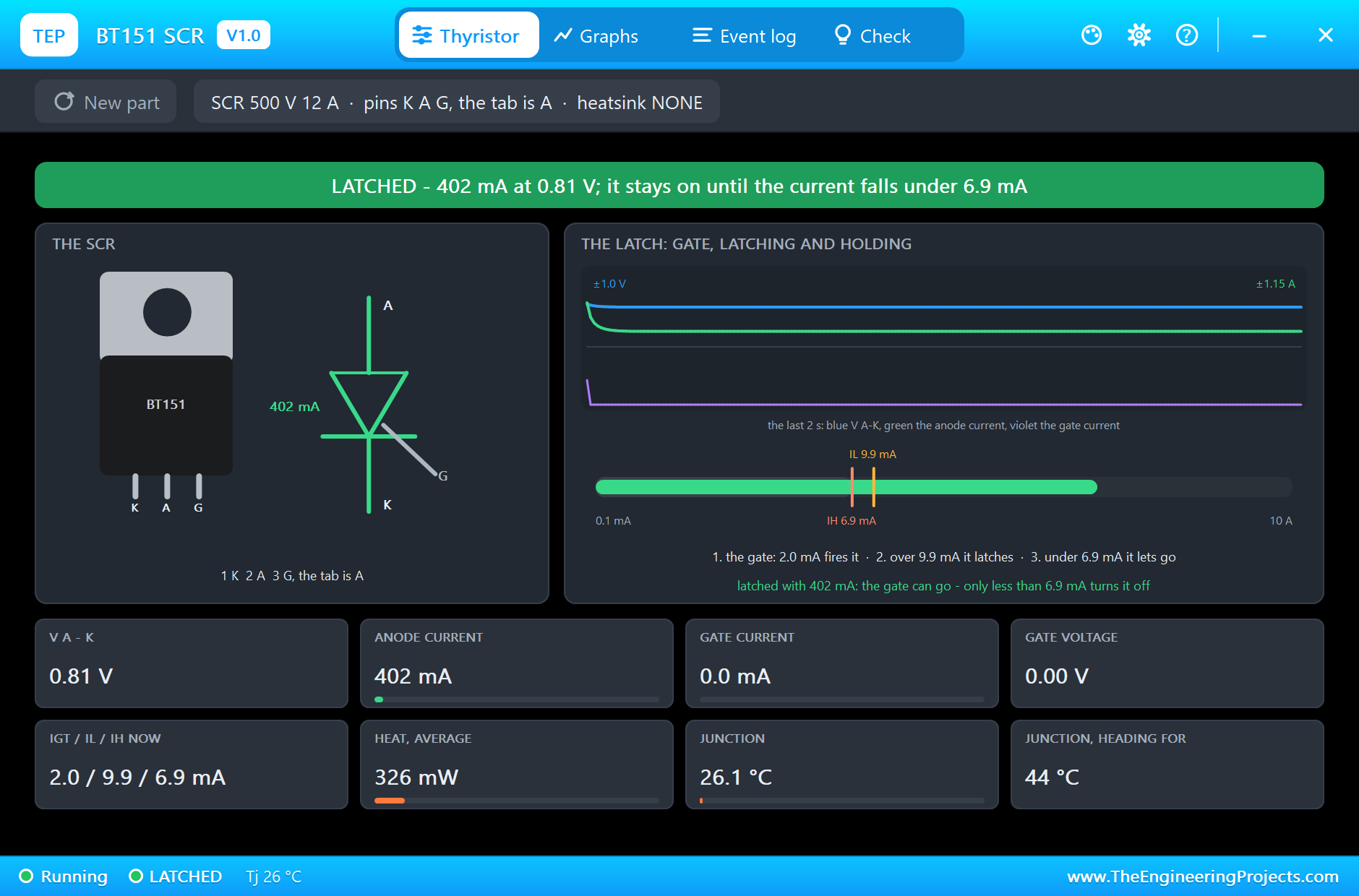
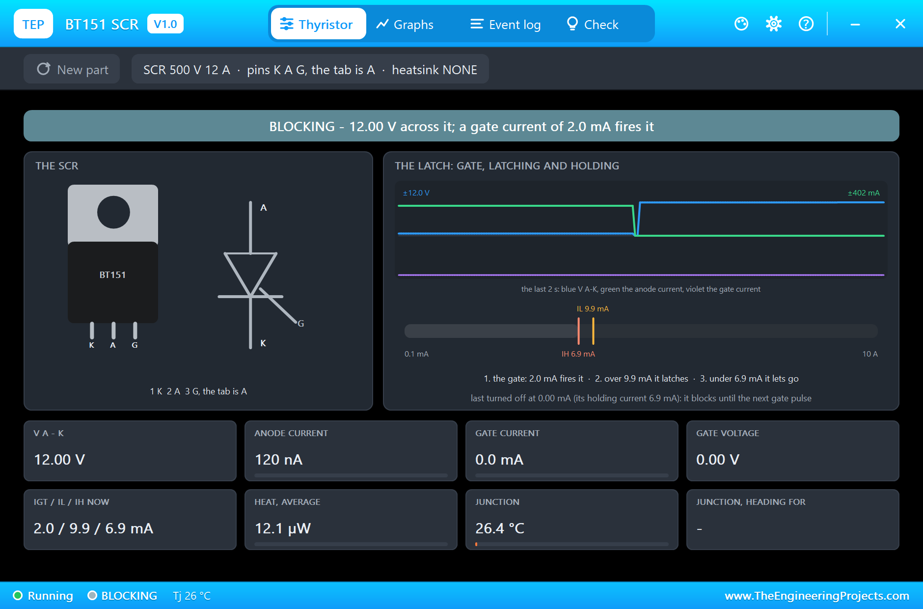
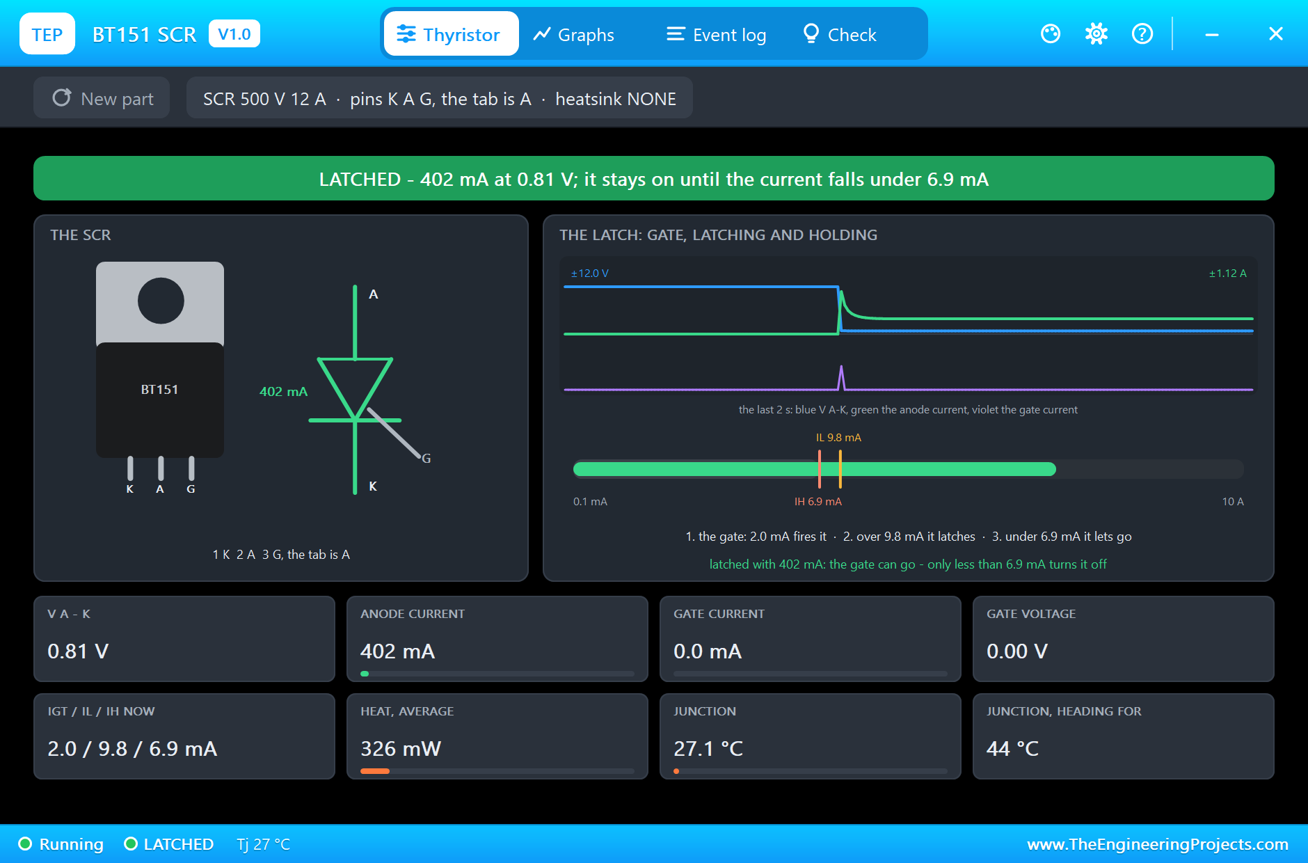
Press Run. At one second the sketch gives the SCR a 1 ms gate pulse of about 12.4 mA, and L2 lights. The pulse is long gone, but the bulb stays on: 402 mA flows, far above the 10 mA latching current, and the SCR holds itself on with 0.81 V across it. The Event log records something else: at the moment it latched, 5.3 A flowed. That is the cold filament of the bulb, whose resistance rises tenfold as it heats; the pop-up's scope of the last two seconds shows the current still settling from that inrush to its steady value. The bar below shows the anode current against the holding and latching currents:
Here is the complete circuit running:
The Triac at Two Milliseconds
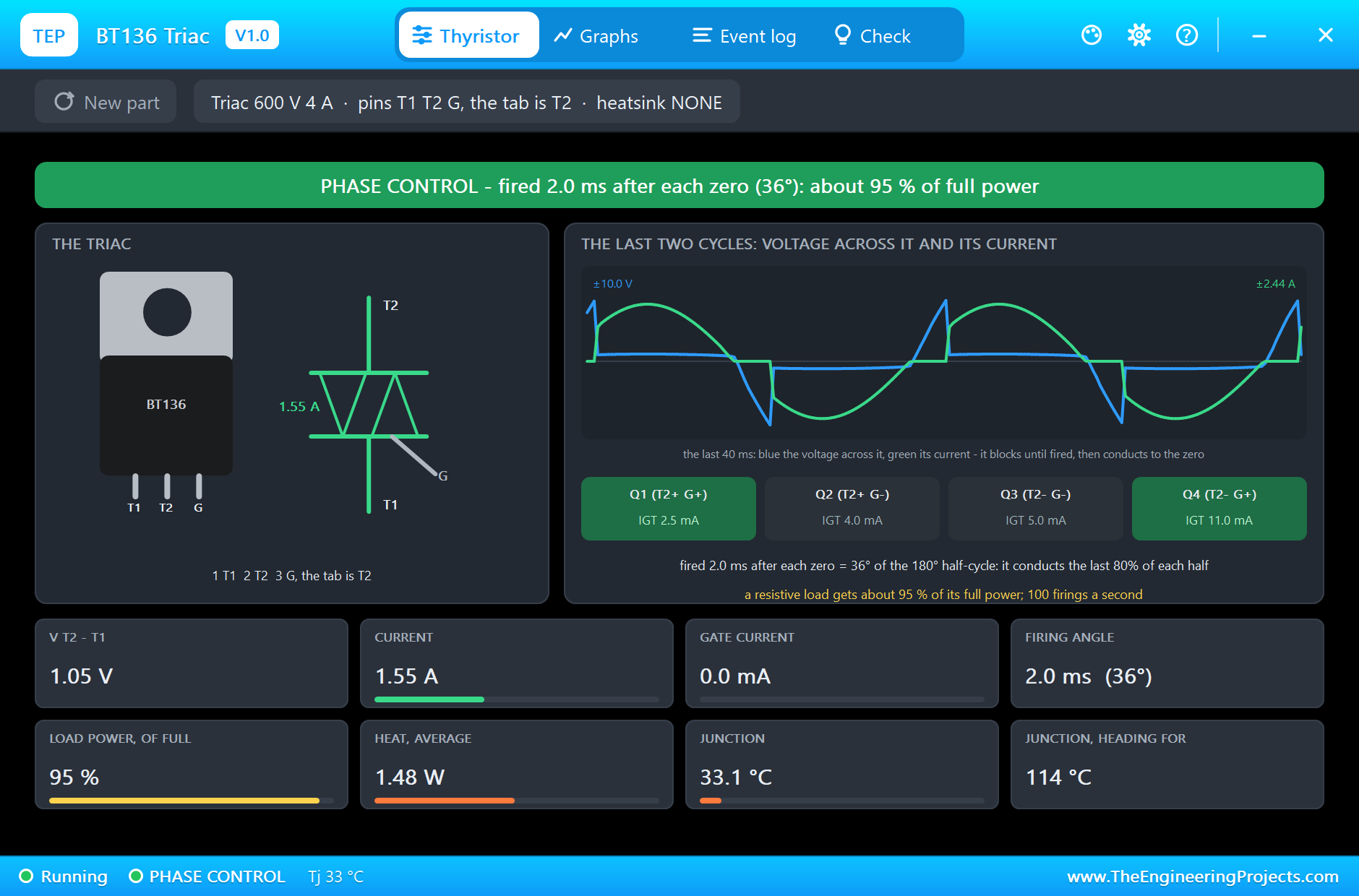
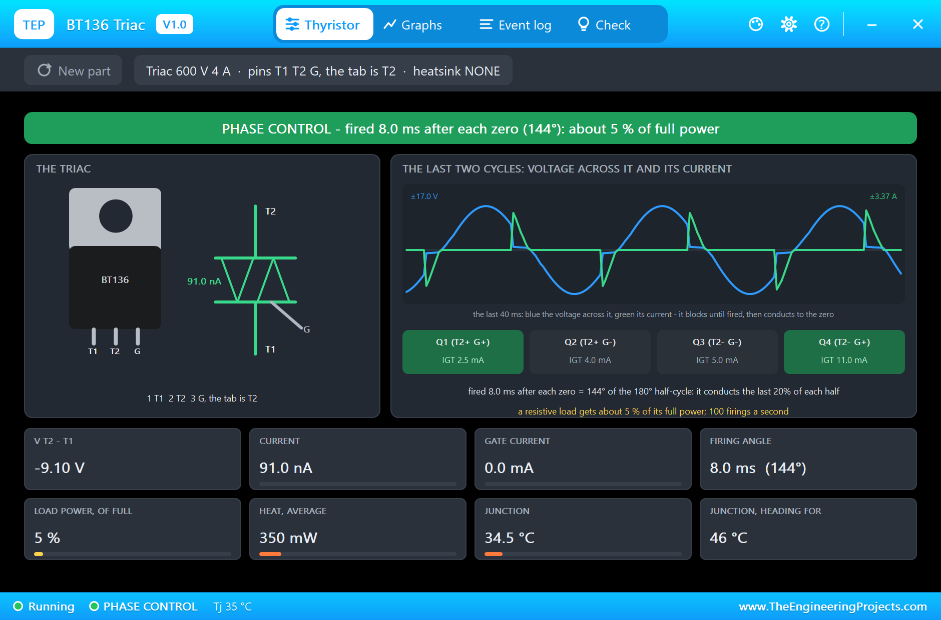
From half a second the sketch fires the triac 2 ms after each zero. The pop-up measures the delay itself, from the zero of the voltage across the triac to the moment it fires: 2.0 ms, or 36° - the sketch's correction for the PC817 lands the pulses on time. The scope shows the voltage across the triac (blue) rising with the AC until the pulse, then collapsing to a volt while the current (green) takes over to the end of the half-cycle. The quadrant row shows it firing in Q1 in the positive half-cycles and Q4 in the negative ones, and the lamp gets about 95 % of full power:
Half Power, and the SCR Turned Off
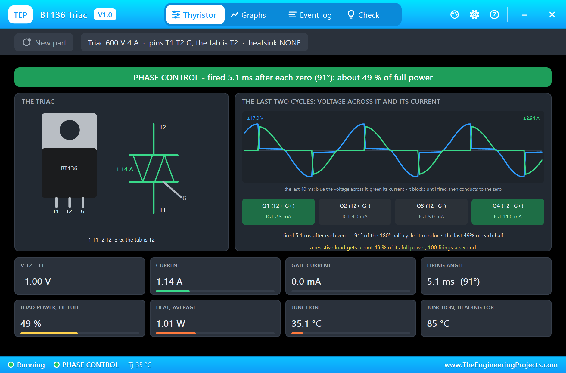
At 3.5 s the delay becomes 5 ms. The triac now blocks for the first half of each half-cycle: the scope shows the voltage across it following the AC up to its peak before the current flows. The pop-up measures 5.0 ms (90°) and about 50 % of full power, and the bulb glows a deep orange:
At 5 s the sketch turns Q3 on for 20 ms. The MOSFET takes the bulb's current away from the SCR, whose current drops to 0.00 mA, under its 6.9 mA holding current, and it turns off. When Q3 lets go, the SCR blocks and L2 stays dark:
Dim, and the SCR Again
At 6.5 s the delay becomes 8 ms: the triac conducts only the last fifth of each half-cycle, 8.0 ms after the zero (144°), and the lamp gets about 5 % of full power. Even so, the scope shows peaks of 3.4 A: the dim filament has cooled and its resistance has fallen. At 8 s the sketch fires the SCR again and it latches as before:
The Monitor
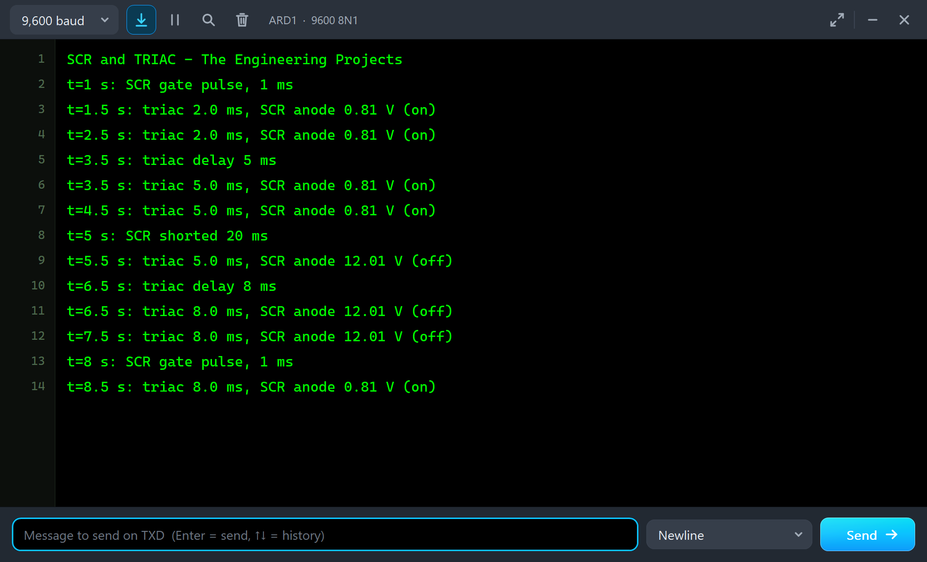
The monitor reports each step and, every second, the triac's delay and the SCR's anode voltage: 0.81 V while it is on, 12.01 V while it blocks:
The Graphs, the Logs and the Check Pages
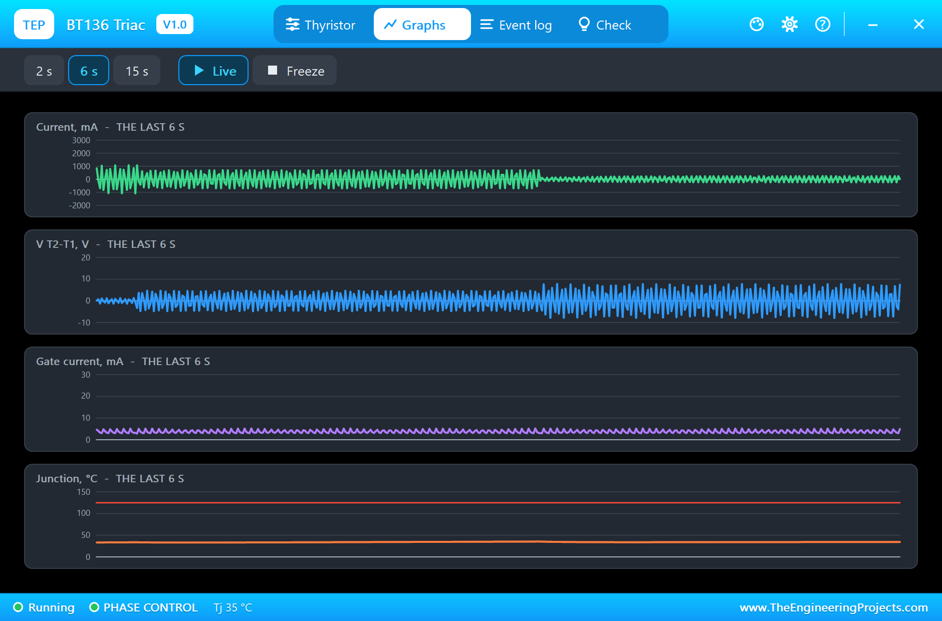
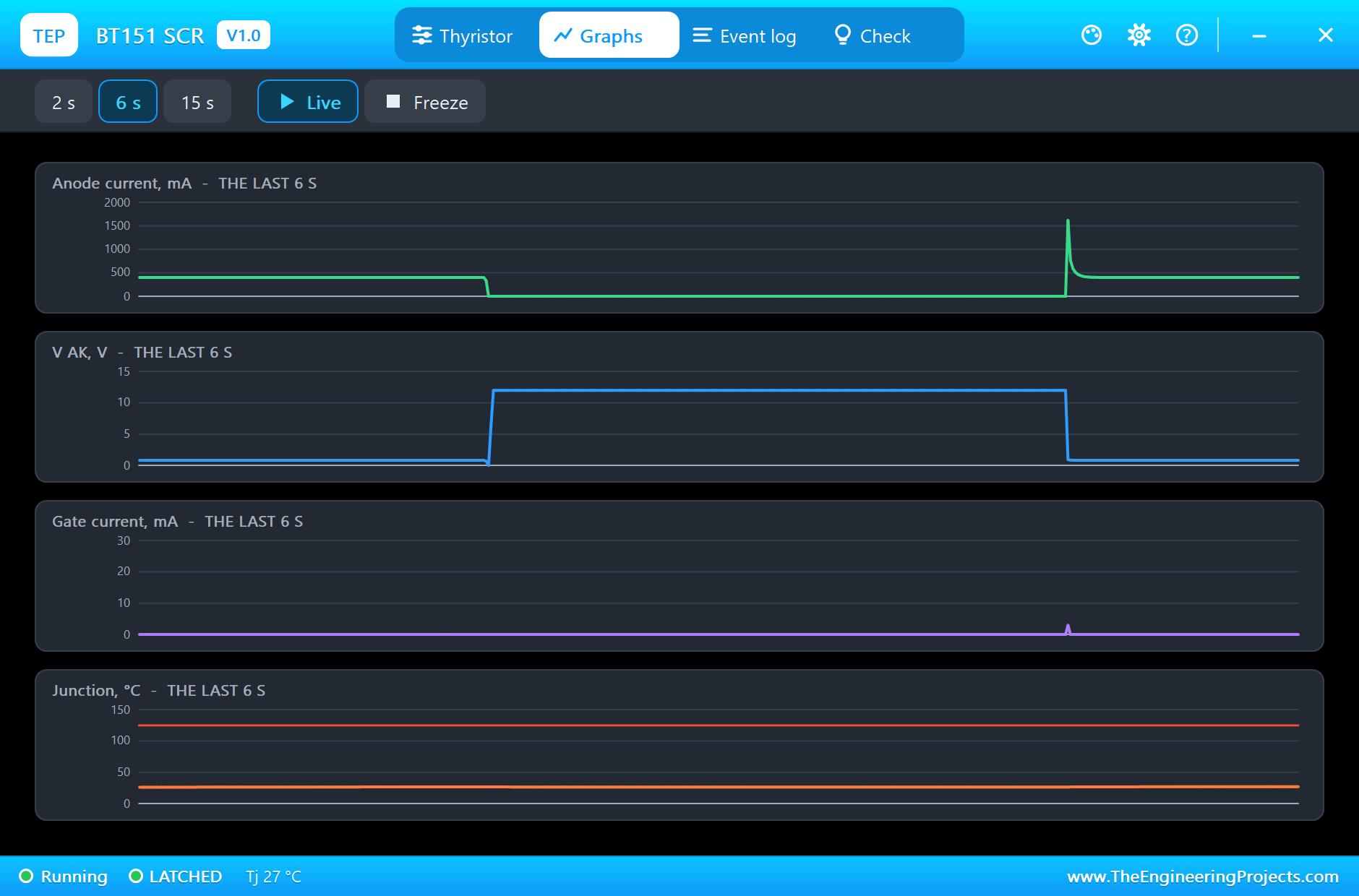
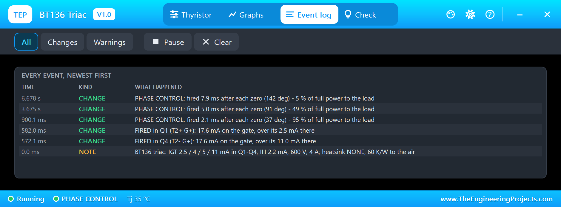
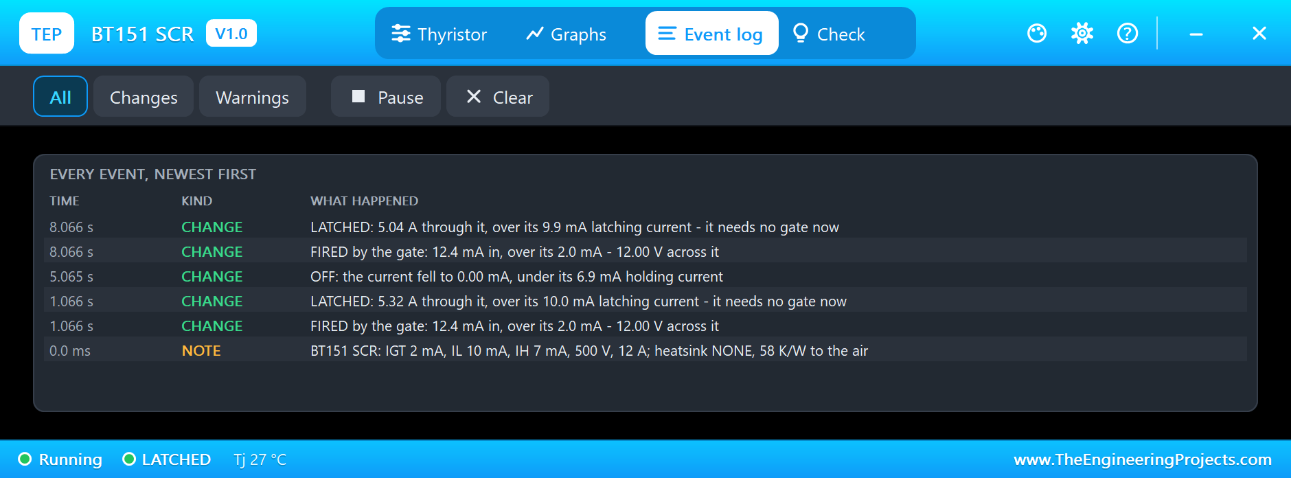
The triac's Graphs page shows the current growing narrower as the delay grows, and the SCR's shows its two latches and the turn-off between them. The Event log of the triac records the first firing in each quadrant and each new firing angle with its share of power; the SCR's records every firing, latch and turn-off with the currents involved:
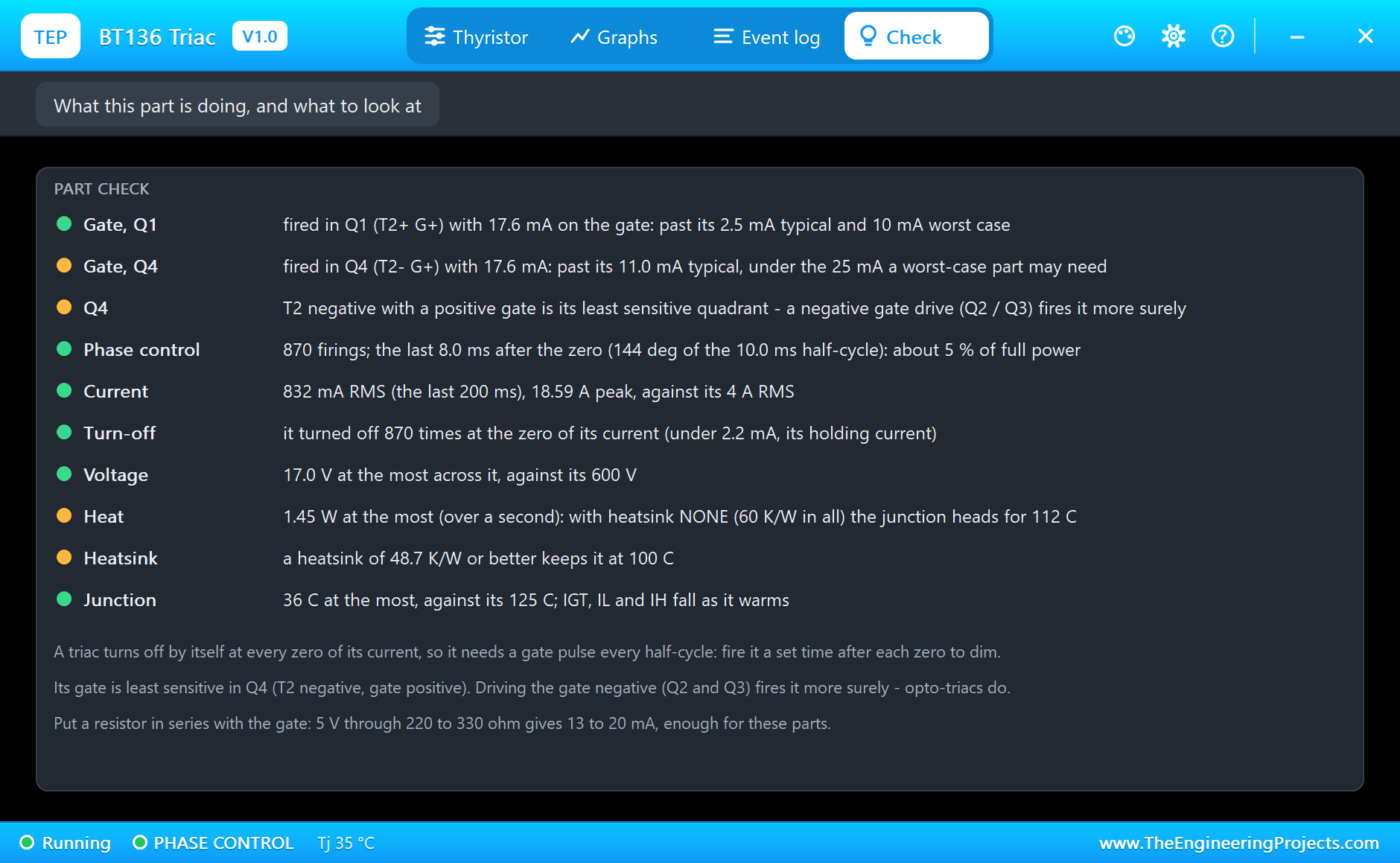
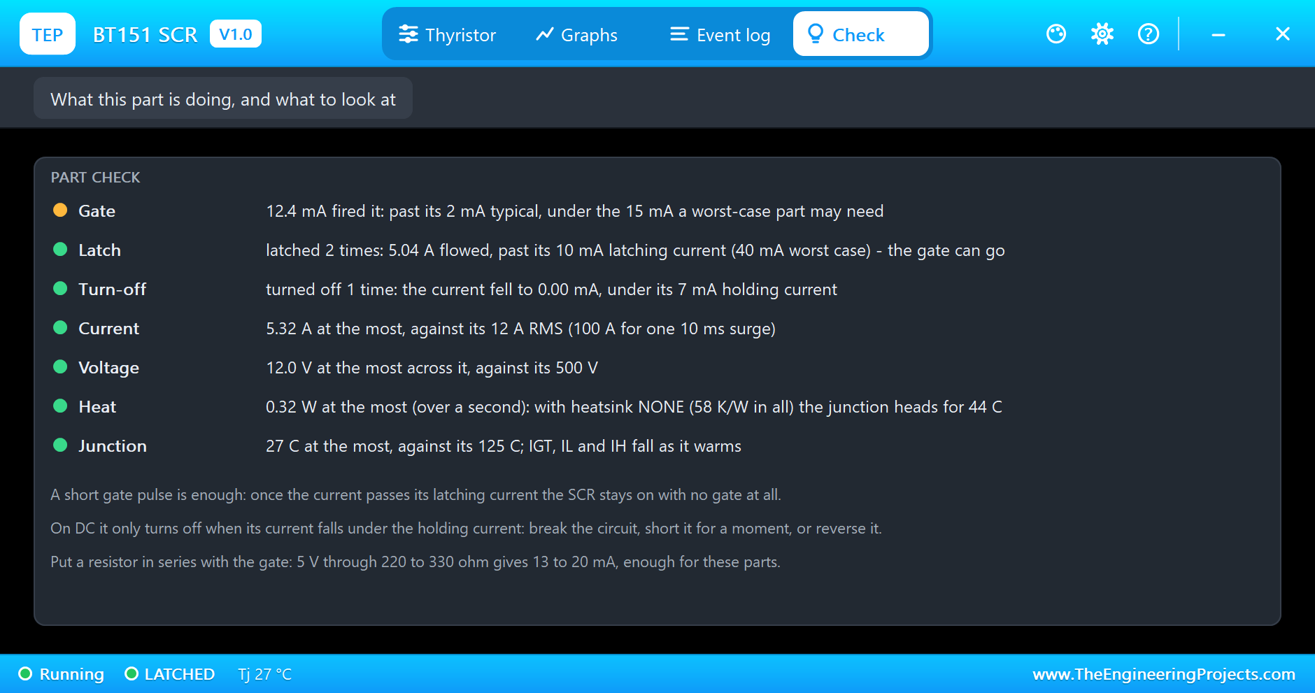
The triac's Check page judges the gate drive quadrant by quadrant: 17.6 mA fires every BT136-600E in Q1, but in Q4 it is past the typical 11 mA and short of the 25 mA a worst-case part may need, and it suggests a negative gate drive. It also counts the firings and the turn-offs at the current zeros and sizes a heatsink. The SCR's Check page confirms the gate current, the latch with its current, and the turn-off under the holding current:
Try It Yourself
- Change R3 to 2k2: about 2 mA reaches the SCR's gate, right at its trigger current - see whether it still fires.
- Replace L2 with a 4.7k resistor: only 2.5 mA flows, under the latching current, and the SCR drops out after each gate pulse.
- Set the triac's delay to 9.5 ms and watch the bulb nearly go out.
- Set Q1's heatsink to SMALL and compare the forecast at 2 ms.
- Take D1 away and see the PC817 lose its negative half-cycles.
Ideas to Extend the Demo
- Read a potentiometer on A1 and make a real dimmer knob.
- Ramp the delay up and down for a slow fade.
- Build a crowbar: fire the SCR across a supply when its voltage passes a limit.
- Count the half-cycles and switch the triac only at the zeros, as a zero-cross solid-state relay does.
Your Own Sketches
The demo sketch is in the zip file, and you can change it in the Arduino IDE. New to Arduino? Start with our Arduino Tutorial for Beginners. Export the compiled binary, and set the UNO's PROGRAM property to the new file. Our guide on How to get the HEX file from Arduino shows you where the file ends up.
Things to Know Before Using a Real Thyristor
- Mains is dangerous: our demo runs on 12 V AC. On the mains, isolate the controller with an opto-triac such as the MOC3021, use a fuse, and let someone qualified check the build.
- Size the gate resistor for the worst quadrant: 25 mA for the BT136-600E in Q4, 15 mA for the BT151.
- Plan the heat: about one watt per amp; the tab is live (A or T2), so insulate it from the heatsink.
- Mind the inrush: cold lamps and motors draw many times their running current.
- Add a snubber (a resistor and a capacitor across the triac) for inductive loads.
Troubleshooting
- It never fires: the gate current is under IGT, or there is no voltage across it.
- DID NOT LATCH: the load current was under the latching current when the gate pulse ended; use a longer pulse or a heavier load.
- It will not turn off on DC: its current must fall under the holding current; break, short or reverse it.
- The dimmer flickers: the firing pulses are late or missing; keep the loop free of waits.
- The part is not simulated:
TEPTHYR.DLLis missing from MODELS and from the project folder.
Limitations of the Simulation
- The turn-on takes one simulation step, not the datasheet's 2 µs, and the turn-off time is not modelled.
- Firing by a fast rise of voltage (dV/dt) and the triac's commutation limits are not modelled.
- The heatsink values are typical; IGT, IL and IH follow the junction temperature on one curve for both parts.
- Arduino is a name of Arduino; this library is not made or endorsed by Arduino or Labcenter.
- Tested in Proteus 8.5 in November 2026 (the demo as shipped). Proteus 7 is not supported.
So, that was all about the SCR and TRIAC Library for Proteus. I hope it helps you understand the latch, try phase control safely at 12 V, and design your own dimmers and switches. If you have any questions, ask in the comments and I will help you out. Till the next tutorial, take care and have fun!