Hello friends, I hope you all are doing great. Today, I am going to share the new Power LED Library for Proteus. A power LED is the LED of torches, bicycle lights, grow lights, spotlights and LED strips: a single emitter that takes a third or two thirds of an amp and gives a hundred or two hundred lumens, a hundred times the current of an indicator LED. That brings two problems an indicator LED never has. It gets hot, and its voltage changes as it does. Drive it the wrong way, or without a heatsink, and it fades, shifts and dies early.
Power LED Library for Proteus
Latest version: V1.0 (November 2026, this tutorial)
Other component libraries: C945 Transistor · PC817 Optocoupler · Relay Module · Resistor · 5 mm LED · Designer Colour LED · Push Button · Active Buzzer · Electrolytic Capacitor · Ceramic Capacitor · Tantalum Capacitor · Film Capacitor · 1N4007 Diode · Zener Diode · Schottky Diode · Supercapacitor · Photodiode · RGB LED · Bridge Rectifier · Flashing LED · Bi-Colour LED · SMD LED · Slide Switch · Toggle Switch · Rocker Switch · Micro Limit Switch · Emergency Stop Switch · SMD Resistor · Power Resistor · Resistor Network · Potentiometer · Trimmer Potentiometer · Slide Potentiometer · NTC Thermistor · DIP Switch · Fuse · Passive Buzzer · Mini Speaker · 7-Segment Display · LED Bar Graph · IR / UV LED · Small Transistors · TIP122 Darlington · N-MOSFET · P-MOSFET · PC817 Optocoupler · Filament Bulb · Voltage Regulator · SCR and TRIAC · Inductor · Toroid Inductor · Crystal
Helping Tools
- Serial Monitor Advance: a serial terminal window for the UART of your board
- Serial Monitor Expert: the serial monitor with extra debugging tools
- LCD Library for Proteus V3.0: 16x2, 20x4 and I2C LCDs to show your readings
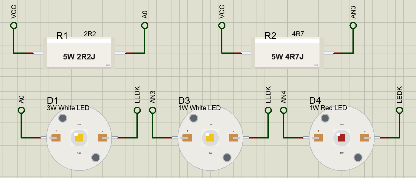
Our library has three power LEDs at true scale on their 20 mm round aluminium boards: a 1 W white (350 mA), a 3 W white (700 mA) and a 1 W red (350 mA). The model has the junction, whose forward voltage falls about 2 mV for every degree it warms; the heat path from the junction to the board and on to the air, through a heatsink you choose; and the light, which follows the current and falls with the heat. The pop-up shows each temperature on that path and forecasts where the junction is heading. The demo compares the two ways to feed a power LED, a resistor and a constant-current driver, side by side.
NOTICE: Our team has put a lot of effort into these small parts: the bodies, the animation and the pop-ups are all our own design, and you get them free. Your feedback is the fuel that keeps us going, so please tell us what you think in the comments below or in the Power LED board of our forum. And if our free libraries help you, you can buy us a coffee. So, let's get started with the Power LED Library for Proteus:
What is a Power LED?
A power LED is a light-emitting diode built for high current: a larger chip, a thermal pad underneath to carry its heat away, and a silicone lens on top. On its own it is a tiny square a few millimetres across, so it is sold soldered to a small aluminium board, a metal-core PCB that spreads the heat and can be screwed to a heatsink. The usual boards are 20 mm across, round or star-shaped, with a pad marked + and a pad marked - for the wires. White power LEDs are blue LEDs under a yellow phosphor, which is why their lens looks yellow when off; red ones use a different semiconductor and have a lower voltage.
| LED | Current | Forward voltage | Light | Maximum |
|---|---|---|---|---|
| 1 W white | 350 mA | 3.2 V | about 100 lm | 500 mA, 125 C |
| 3 W white | 700 mA | 3.4 V | about 200 lm | 1000 mA, 125 C |
| 1 W red | 350 mA | 2.3 V | about 40 lm | 500 mA, 125 C |
Why Heat Matters
Even a good white LED turns only about a quarter to a third of its electrical power into light; the rest becomes heat in the junction, a few square millimetres of semiconductor. A 3 W LED therefore has to get rid of more than 2 W from a speck the size of a grain of rice. The heat flows from the junction into the aluminium board and from the board into the air or a heatsink, and every step of that path has a thermal resistance in kelvins per watt. The junction runs hotter than the air by the power times the sum of those resistances. A bare 20 mm board in still air is about 35 K/W, so a 3 W LED on it heads for around 100 °C at the junction; on a proper heatsink it stays far cooler.
A hot junction costs in three ways. The light falls: about 0.3 % per degree for white and about 0.8 % for red. The colour shifts. And the life shortens sharply above about 100 °C, while the absolute limit is typically 125 °C. The heat does not arrive at once: the junction heats in a fraction of a second, but the board and heatsink take a minute or more, so an LED that looks fine in the first seconds may be heading somewhere much hotter.
The Forward Voltage Falls as It Warms
Like every diode, an LED's forward voltage falls as its junction warms, by about 2 mV per degree. That sounds small, but it decides how a power LED must be driven. With a resistor from a fixed supply, the current is the voltage left over after the LED, divided by the resistor. As the LED warms, its voltage falls, more voltage is left for the resistor, and the current rises; more current means more heat, and the voltage falls further. With a small resistor and a hot LED this can run away. A resistor feed is fine for indicator LEDs, but for power LEDs it is a compromise.
Constant Current
The right way to feed a power LED is a constant current: a circuit that sets the current itself, whatever the LED's voltage does. Dedicated LED driver chips do this efficiently, but the classic two-transistor circuit shows the idea best. A MOSFET passes the LED's current, which flows through a small sense resistor. A small NPN transistor watches the voltage across that resistor. When it reaches about 0.6 V, the NPN starts to conduct and pulls the MOSFET's gate down, so the current settles at about 0.6 V divided by the sense resistor: 600 mA with 1 Ω. The LED's voltage can do what it likes; the current holds.
Where They Are Used
Power LEDs light torches and headlamps, bicycle and car lights, spotlights and floodlights, grow lights for plants, stage lighting, and the backlights of signs. In a microcontroller project they are switched or dimmed through a MOSFET or a driver, and their heatsink is part of the design from the start.
Features of the Power LED Library for Proteus
- The real look, at true scale: 20 mm round aluminium boards with the emitter, its lens and phosphor or red die, the + and - pads and our small TEP signature.
- A glowing symbol: the lens and the board light up with the LED's output, and the board takes a warm tint as it heats.
- A real junction: its forward voltage set from the rating and falling about 2 mV per degree, so a resistor feed drifts as it would.
- The heat path: junction, board and air, each with its heat capacity, and the board's heatsink a property: NONE, SMALL or LARGE.
- A forecast: the pop-up shows where the junction is heading once the board has warmed, and the Check page sizes a heatsink to keep it under 100 °C.
- The light: it follows the current with a slight droop and falls with the junction temperature, red faster than white.
- A pop-up for each LED: the LED, the heat path, eight live values, graphs, an event log and a check page.
- A complete package: about 2.6 MB with the library, our Arduino UNO V4.0, our power resistors, MOSFETs, transistor and resistors and the demo, without the source code of the model.
The Power LEDs in Proteus
The devices are POWERLED1WWHITETEP, POWERLED3WWHITETEP and POWERLED1WREDTEP in TEPPOWERLED.LIB, under Optoelectronics, Power LEDs, with the prefix D and the model TEPPOWERLED.DLL. Search POWERLED in Pick Devices. Each is drawn from above at true scale, with its anode, +, on the left and its cathode, -, on the right.
The Properties
| Property | What it does |
|---|---|
| Part (VALUE) | the label: 1W White LED, 3W White LED or 1W Red LED |
| Heatsink | NONE (the bare board, 35 K/W), SMALL (12 K/W) or LARGE (4 K/W) |
Download Power LED Library for Proteus
Click the button below to download Power-LED-Library-for-Proteus-v1.0.zip (about 2.6 MB, without the source code of the models):
Power LED Library for Proteus V1.0- README.txt: installation, the demo, the two ways to feed a power LED, troubleshooting and the limits.
- Proteus Library Files:
TEPPOWERLED.LIB, our resistor, power resistor, N-MOSFET and small transistor libraries, and ourArduinoV4TEP.LIB. - Proteus Model Files:
TEPPOWERLED.DLL, the DLLs of those parts andTEPARDUINO.DLL. - Arduino Code: the demo sketch.
- Proteus Simulation: the demo project, its HEX file and copies of the DLLs.
No Proteus yet? Read How to Download and Install Proteus 7 and 8. New to libraries? Follow How to Install a New Library in Proteus.
How to Install Power LED Library for Proteus
- Close Proteus and extract the whole zip file, for example to your Desktop.
- Copy the files from Proteus Library Files into the LIBRARY folder of Proteus.
- Copy the files from Proteus Model Files into the MODELS folder.
- Delete
TEPPOWERLED.IDXfrom the LIBRARY folder if it is there. - Start Proteus, press P and search for POWERLED.
Demo: A Resistor Against a Constant Current
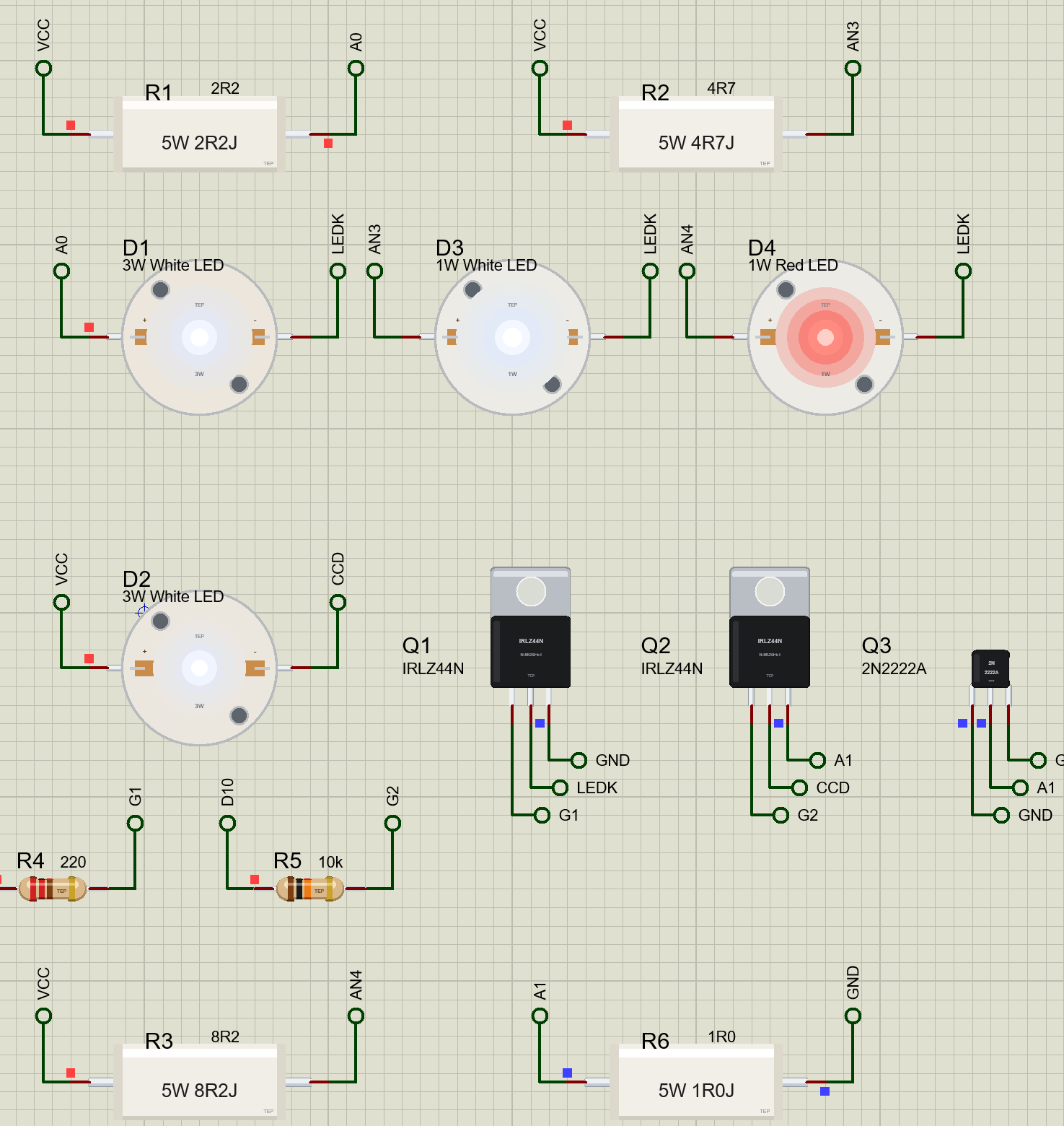
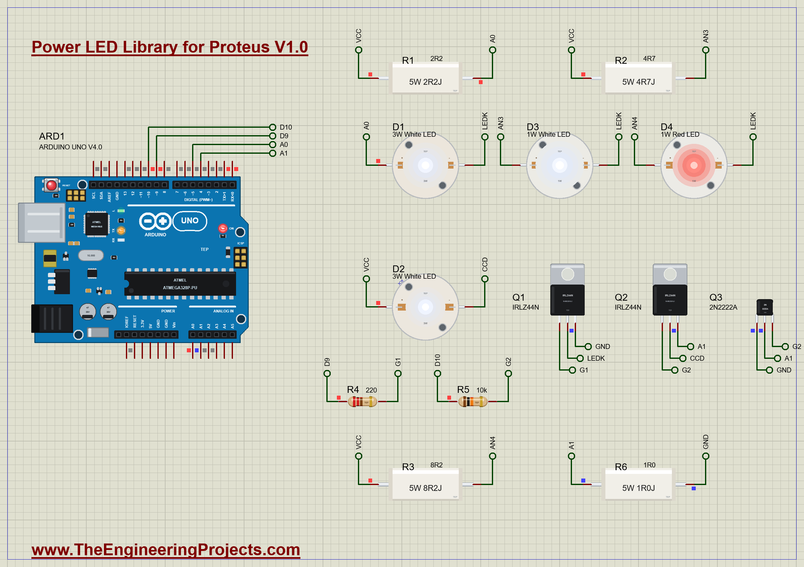
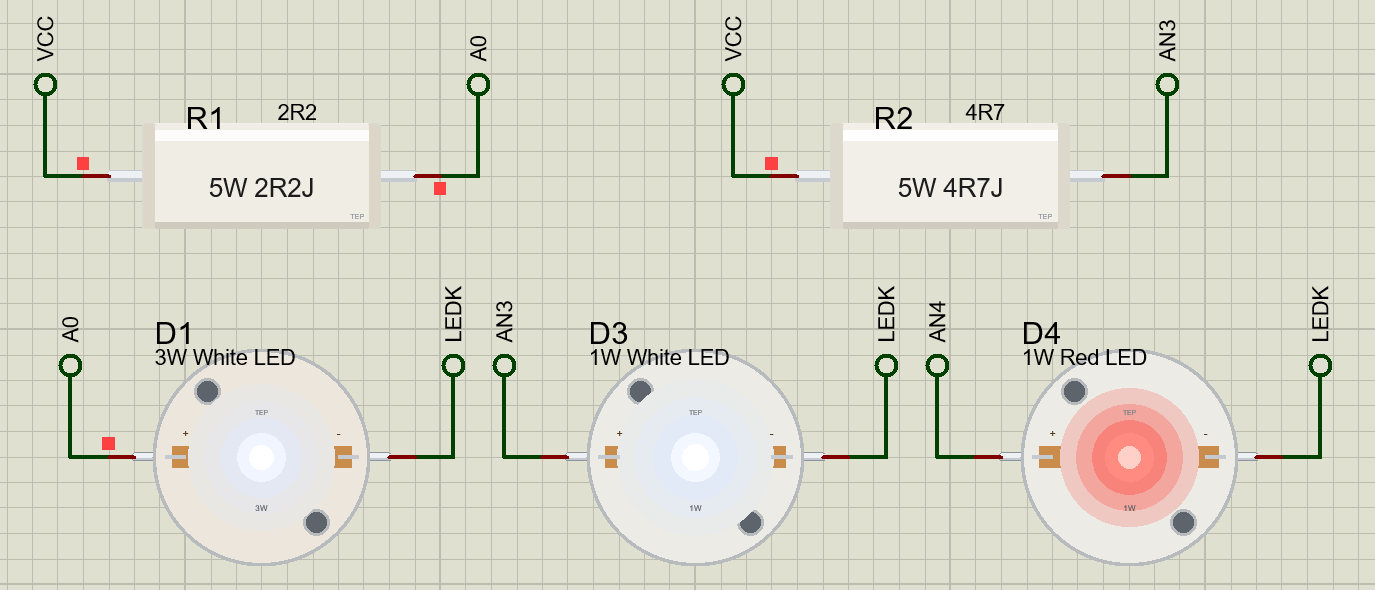
Two identical 3 W white LEDs on bare boards, fed two ways from the 5 V rail. D1 is fed through R1, a 2.2 Ω power resistor, and switched by Q1, an IRLZ44N on D9 through R4 (220 Ω). D2 is fed by the constant-current driver: Q2, an IRLZ44N, passes its current through R6, a 1 Ω sense resistor, and Q3, a 2N2222A, holds Q2's gate so that about 0.6 V stays across R6; D10 enables it through R5 (10k). Two 1 W LEDs share Q1 with D1: D3, white, on a small heatsink through R2 (4.7 Ω), and D4, red, on a large heatsink through R3 (8.2 Ω). The Arduino measures D1's current from the voltage on its resistor (A0) and D2's from the voltage on R6 (A1).
Open Power-LEDs-ArduinoUnoV4.pdsprj. It runs on our Arduino UNO Library for Proteus V4.0, with its built-in monitor, the same window as our TEP Serial Monitor Advance for Proteus. The resistors come from our Power Resistor Library for Proteus, the MOSFETs from our N-MOSFET Library for Proteus and the 2N2222A from our Small Transistors Library for Proteus.
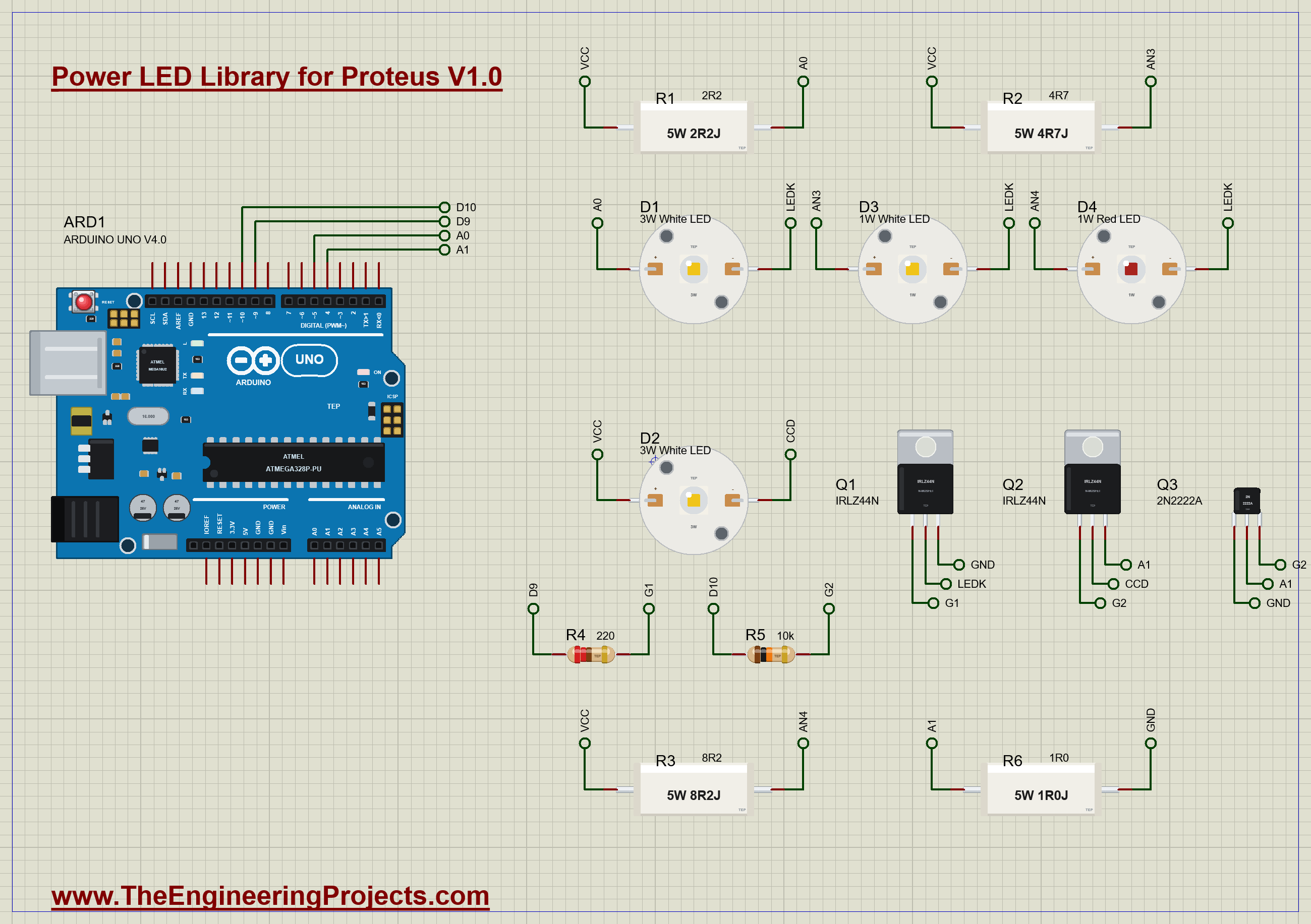
| Part | Connection | Job |
|---|---|---|
| D1 3W, R1 2R2, Q1 | VCC - R1 - D1 - Q1, A0 on the anode | the resistor feed |
| D2 3W, Q2, Q3, R6 1R0, R5 10k | VCC - D2 - Q2 - R6 - GND, A1 on R6 | the constant current |
| D3 1W white, R2 4R7 | VCC - R2 - D3 - Q1, small heatsink | a cool 1 W |
| D4 1W red, R3 8R2 | VCC - R3 - D4 - Q1, large heatsink | a cool red |
| R4 220 | D9 to Q1's gate | the switch |
The Sketch
The sketch switches everything on in setup. To read a voltage steadily it averages sixteen readings of the ADC:
float volts(byte pin) {
  long sum = 0;
  for (byte k = 0; k < 16; k++) sum += analogRead(pin);
  return sum / 16.0 * VREF / 1023.0;
}
Every 2 s it turns the two voltages into currents. D1's is the voltage across R1, 5 V minus its anode, divided by 2.2 Ω; D2's is the voltage on R6 divided by 1 Ω:
    const float i1 = (VREF - volts(ANODE_1)) / R1_OHMS;
    const float i2 = volts(SENSE_2) / R6_OHMS;
Run the Demo
At Switch-On
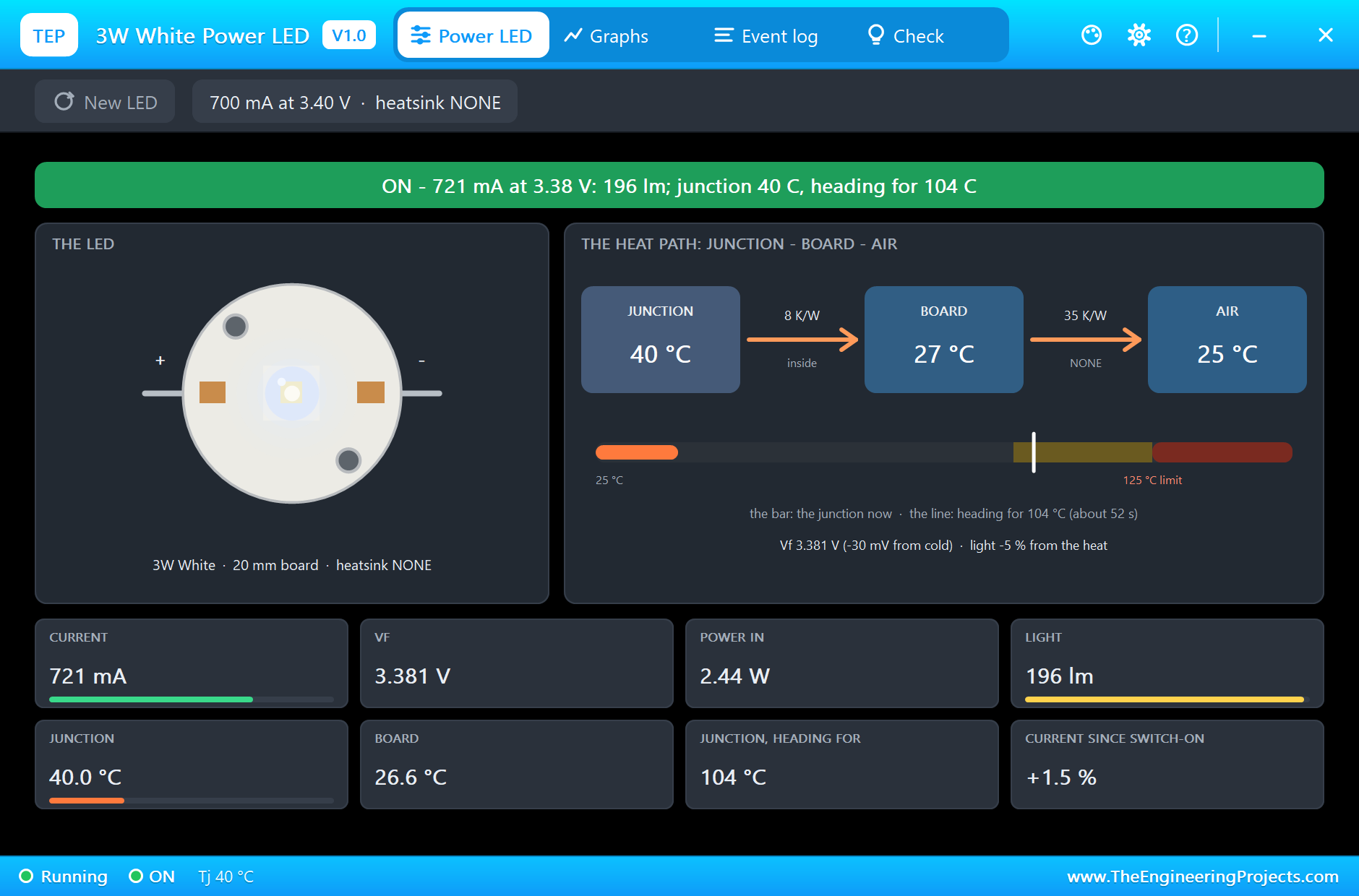
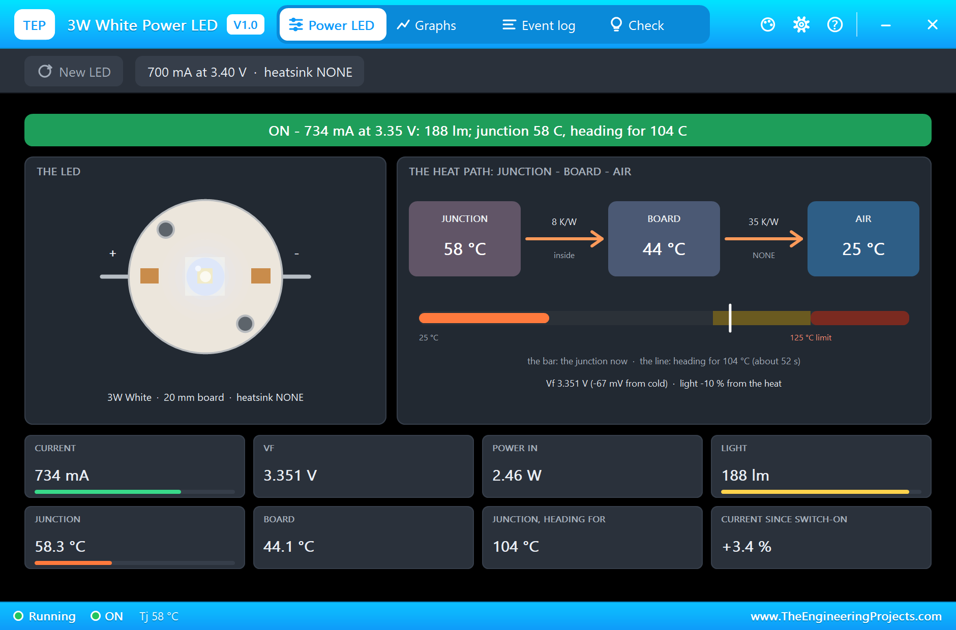
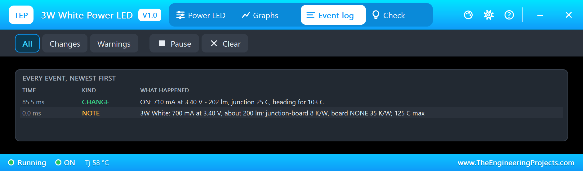
Press Run. At the moment it switches on, D1 takes 710 mA through its resistor, and its junction is still at room temperature. Within two seconds the junction has already warmed to 40 °C, because the heat reaches it first, and its current has risen to 721 mA. The pop-up shows the heat path: junction, board and air, with the bar of the junction temperature and a white line where it is heading, 104 °C on the bare board:
Here is the complete circuit running:
Twenty Seconds Later
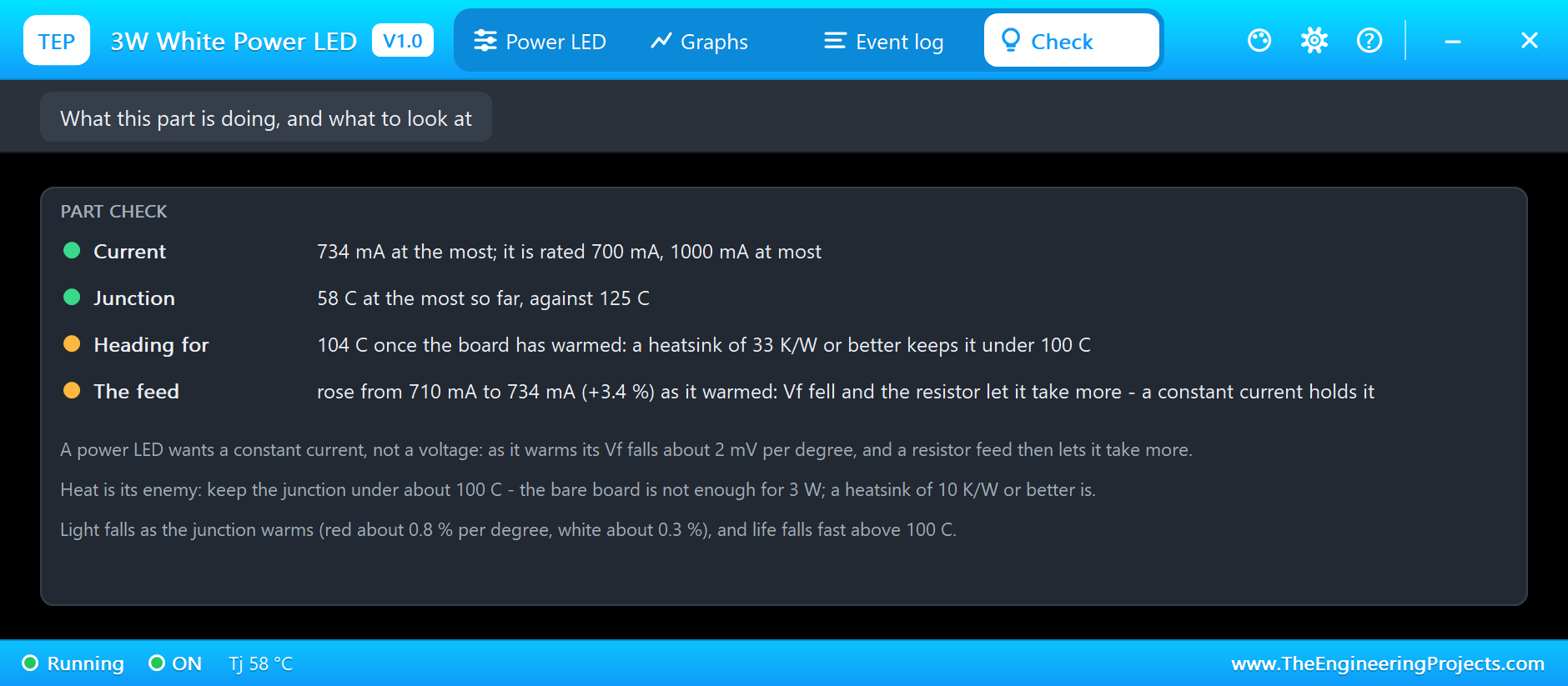
After twenty seconds D1's board has warmed to 44 °C and its junction to 58 °C. Its forward voltage has fallen by 66 mV, to 3.351 V, and through the same resistor its current has crept up to 734 mA, 3.4 % more than at switch-on, and still rising with the board. Its light is down about 10 % from the heat, to 188 lm:
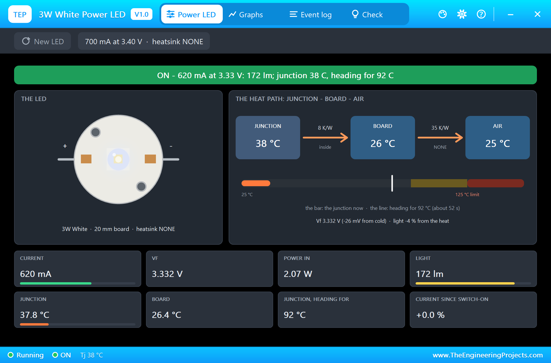
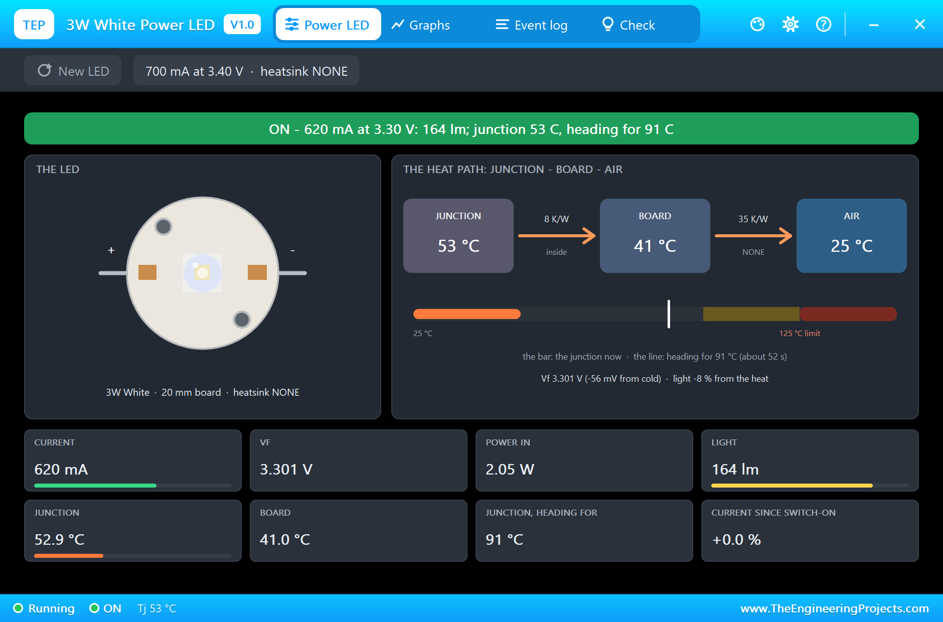
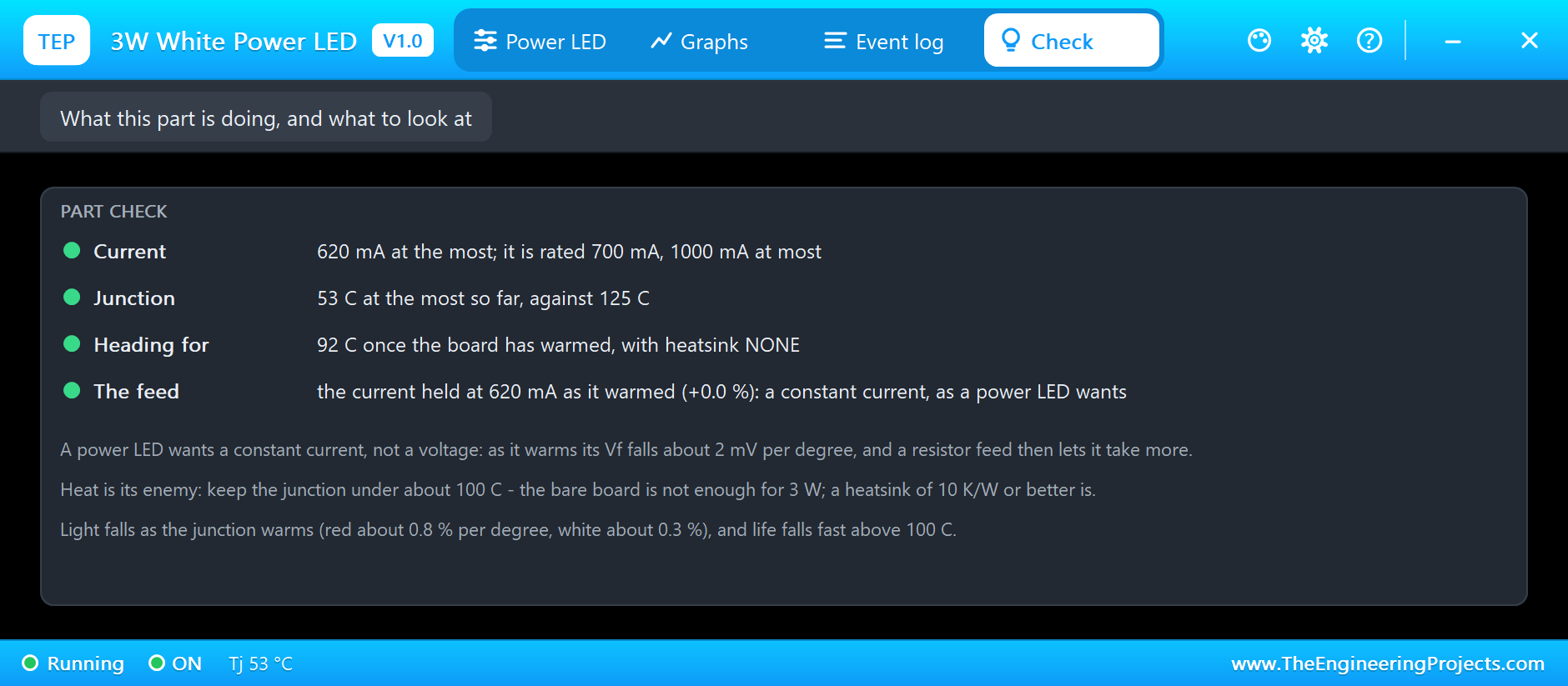
D2, on the constant-current driver, started at 620 mA and is still at 620 mA. Its forward voltage fell too, by 56 mV, but the driver simply let Q2 take the difference. Its junction is at 53 °C and heading for 91 °C, lower than D1 because it carries less current:
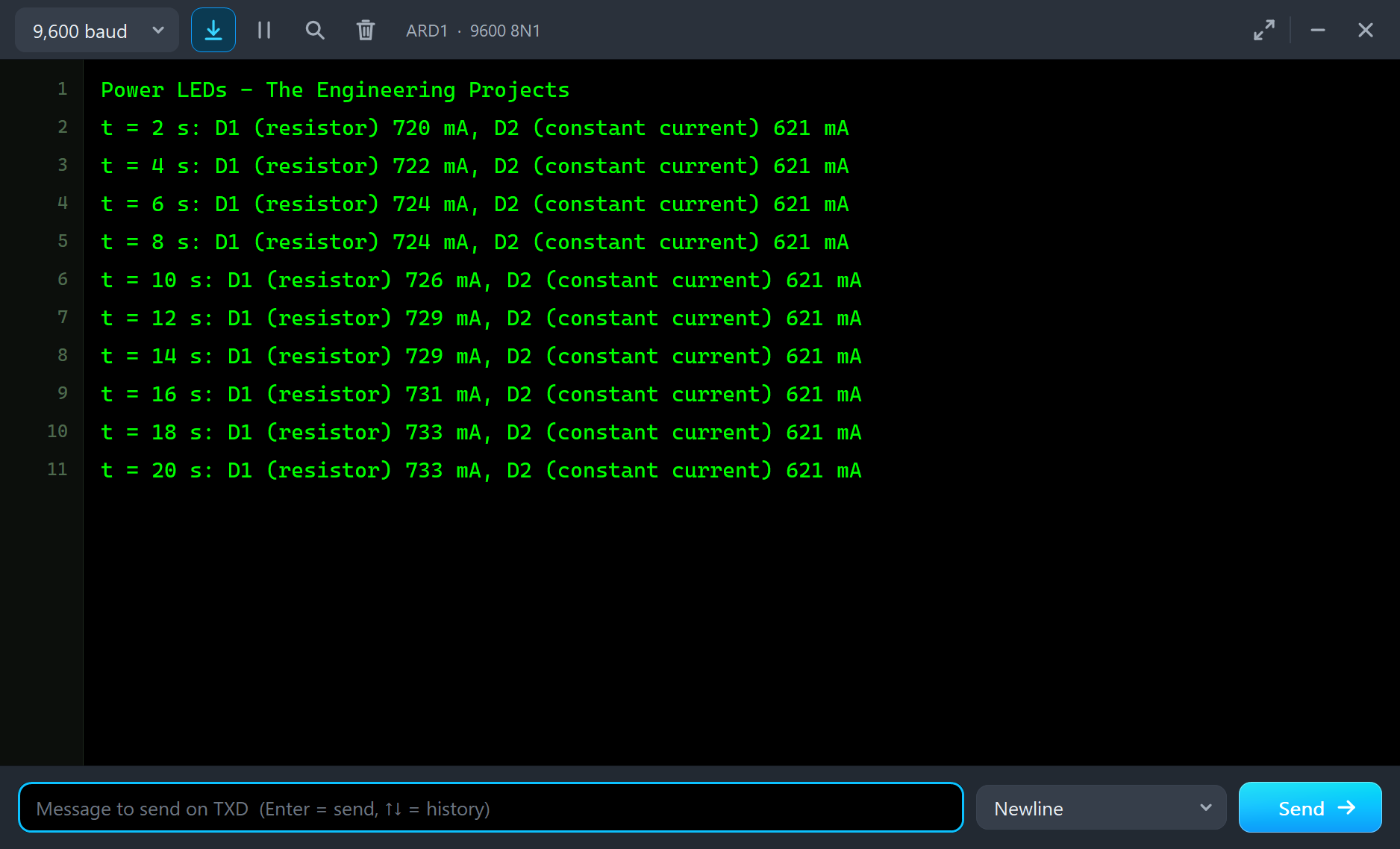
The Arduino sees exactly this. Every two seconds the monitor prints D1 creeping from 720 mA to 733 mA while D2 reads 621 mA every time:
Heatsinks
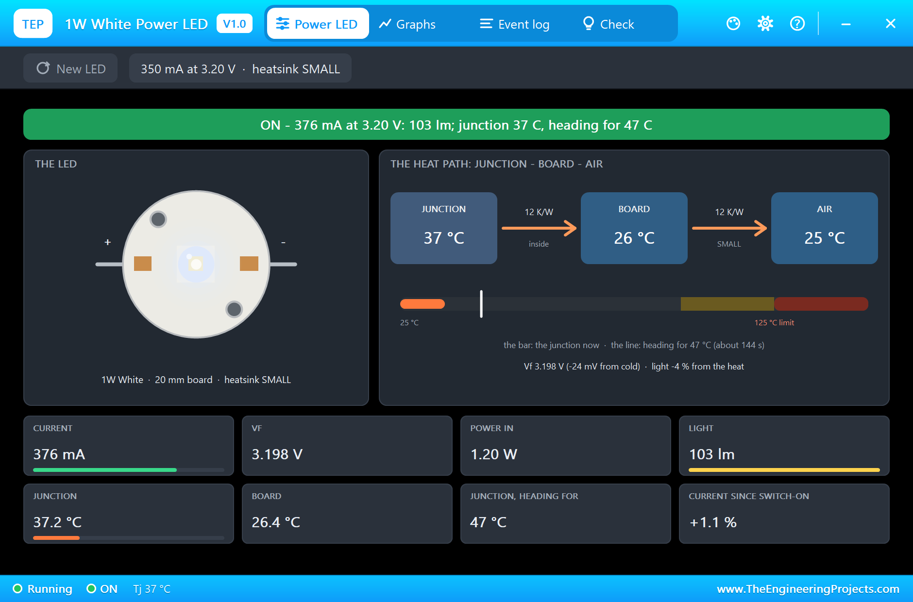
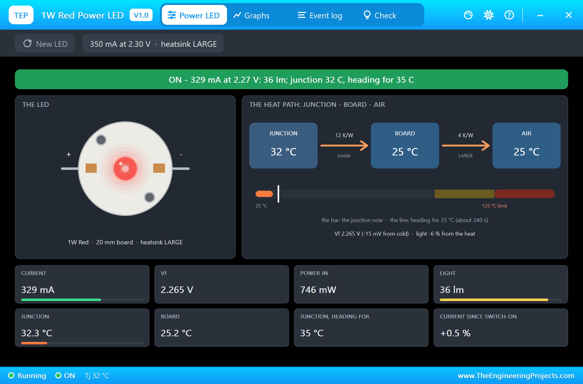
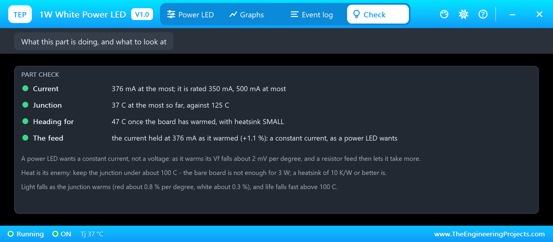
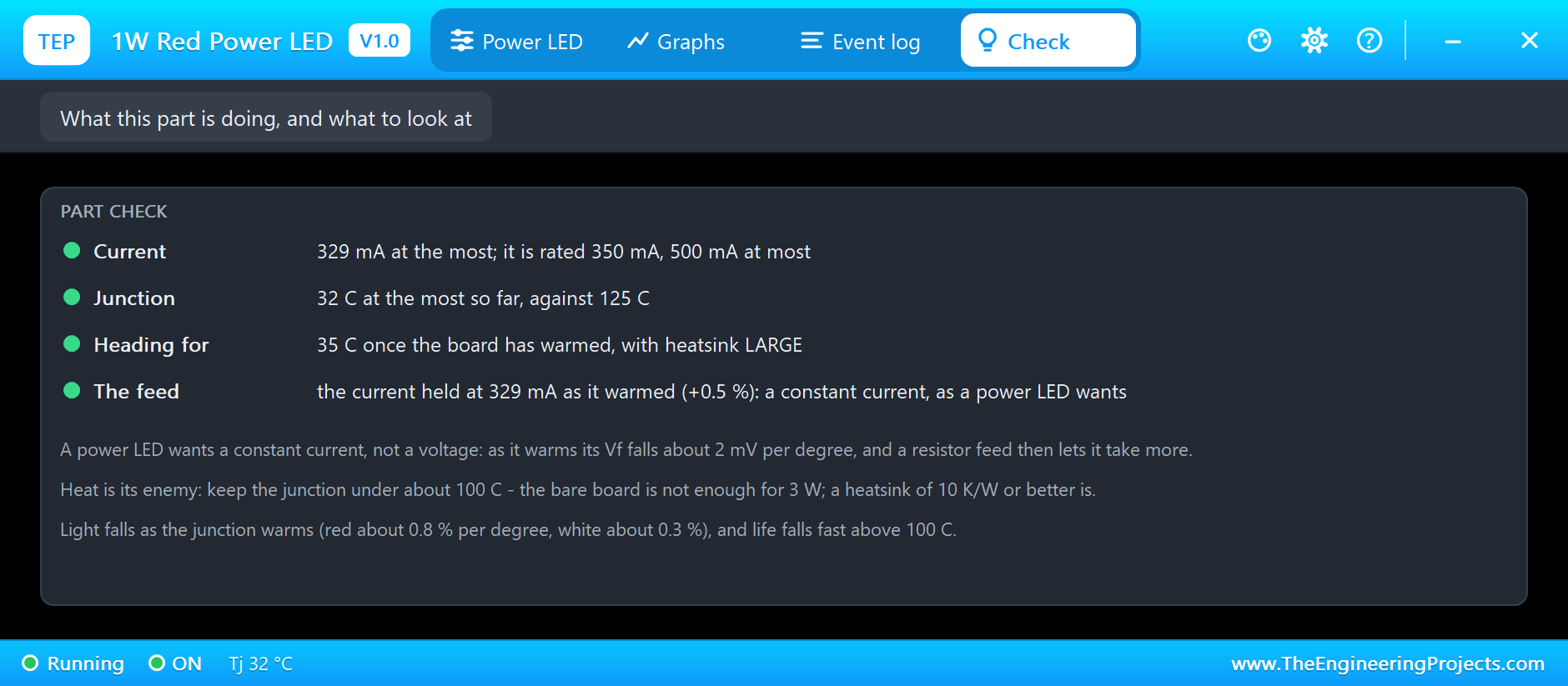
The two 1 W LEDs show what a heatsink does. D3, white, takes 376 mA on a small heatsink: its junction sits at 37 °C and is heading for only 47 °C. D4, red, takes 329 mA on a large heatsink: 32 °C, heading for 35 °C. Red LEDs lose light faster with heat, so they gain most from a good heatsink:
The Graphs, the Log and the Check Pages
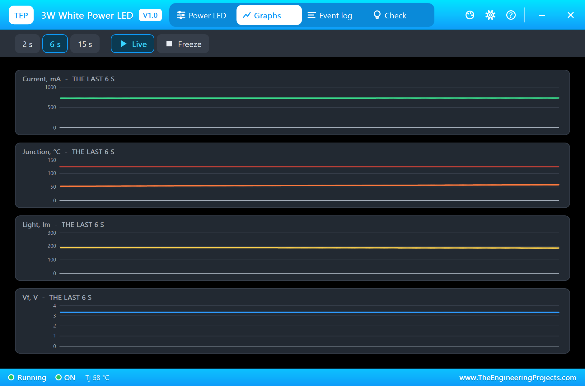
Over twenty seconds the changes are slow, and the Graphs page shows them as gentle slopes: D1's current a little higher, its junction rising, its light and its Vf a little lower. The Event log records the switch-on with the forecast already in it:
The Check pages give the design advice. D1's says its junction is heading for 104 °C and that a heatsink of 33 K/W or better would keep it under 100 °C, and it flags the creeping current of the resistor feed. D2's confirms the current held. D3's and D4's show cool junctions:
Try It Yourself
- Set D1's heatsink to SMALL and run again: watch the forecast fall below 100 °C.
- Change R1 to 1R0 and see the current and the junction climb.
- Change R6 to 2R2 for a 270 mA driver, or 0R47 for over an amp.
- Swap D2 for the red LED on the same driver: the same current, a different voltage.
- Run the demo for a few minutes and watch D1's board settle.
Ideas to Extend the Demo
- Dim the constant-current LED with PWM on D10.
- Add an NTC thermistor to the board and lower the current when it gets hot.
- Build a torch with a battery, a button and the driver.
- Make a grow light from several red and white LEDs on one heatsink.
Your Own Sketches
The demo sketch is in the zip file, and you can change it in the Arduino IDE. New to Arduino? Start with our Arduino Tutorial for Beginners. Export the compiled binary, and set the UNO's PROGRAM property to the new file. Our guide on How to get the HEX file from Arduino shows you where the file ends up.
Things to Know Before Using a Real Power LED
- Feed it a constant current: a driver chip or the two-transistor circuit, not a bare resistor from a fixed supply.
- Plan the heatsink: a 3 W LED needs one; spread thermal paste and screw the board down.
- Keep the junction under 100 °C: for light, colour and life.
- Size every part for the current: resistors and transistors carry hundreds of milliamps.
- Do not look into it: a power LED is bright enough to hurt your eyes.
Troubleshooting
- TOO HOT: the junction passed 125 °C; add a heatsink or reduce the current.
- The current creeps up: a resistor feed; use a constant-current driver.
- Dim and cool: too little current; check the resistor or the sense resistor.
- BURNT OUT: too hot or too much current; New LED fits another.
- The part is not simulated:
TEPPOWERLED.DLLis missing from MODELS and from the project folder.
Limitations of the Simulation
- The thermal resistances and heat capacities are typical of such LEDs and boards, not taken from one datasheet.
- The colour shift with current and temperature is not modelled.
- The slow loss of light over thousands of hours is not modelled.
- Arduino is a name of Arduino; this library is not made or endorsed by Arduino or Labcenter.
- Tested in Proteus 8.5 in November 2026 (the demo as shipped). Proteus 7 is not supported.
So, that was all about the Power LED Library for Proteus. I hope it helps you light your projects brightly and keep your LEDs cool, and see why a constant current and a heatsink matter before you build. If you have any questions, ask in the comments and I will help you out. Till the next tutorial, take care and have fun!