Hello friends, I hope you all are doing great. Today, I am going to share the new PC817 Optocoupler Library for Proteus. An optocoupler joins two circuits with nothing but light: an infrared LED on one side, a phototransistor on the other, and a clear gap between them that can hold off thousands of volts. It is how a 3.3 V or 5 V microcontroller reads a 24 V machine signal, how it switches a load on another supply without sharing its ground, and how a mains power supply tells its controller what the output is doing.
PC817 Optocoupler Library for Proteus
Latest version: V1.0 (November 2026, this tutorial)
Other component libraries: C945 Transistor · PC817 Optocoupler · Relay Module · Resistor · 5 mm LED · Designer Colour LED · Push Button · Active Buzzer · Electrolytic Capacitor · Ceramic Capacitor · Tantalum Capacitor · Film Capacitor · 1N4007 Diode · Zener Diode · Schottky Diode · Supercapacitor · Photodiode · RGB LED · Bridge Rectifier · Flashing LED · Bi-Colour LED · SMD LED · Slide Switch · Toggle Switch · Rocker Switch · Micro Limit Switch · Emergency Stop Switch · SMD Resistor · Power Resistor · Resistor Network · Potentiometer · Trimmer Potentiometer · Slide Potentiometer · NTC Thermistor · DIP Switch · Fuse · Passive Buzzer · Mini Speaker · 7-Segment Display · LED Bar Graph · IR / UV LED · Small Transistors · TIP122 Darlington · N-MOSFET · P-MOSFET · Filament Bulb · Power LED · Voltage Regulator · SCR and TRIAC · Inductor · Toroid Inductor · Crystal
Helping Tools
- Serial Monitor Advance: a serial terminal window for the UART of your board
- Serial Monitor Expert: the serial monitor with extra debugging tools
- LCD Library for Proteus V3.0: 16x2, 20x4 and I2C LCDs to show your readings
Our library has two of the most used ones at true scale: the PC817, the small four-pin optocoupler found on almost every relay board and power supply, with its CTR rank (A, B, C or D) printed on its body, and the 4N35, the classic six-pin part whose phototransistor has its base on a pin. The model has the infrared LED, the light as a photocurrent, and a phototransistor whose current transfer ratio rises, peaks and falls with the LED current just as the datasheet curve does, with the charges of its junctions so its switching times follow the load. The demo reads a 24 V switch, drives an isolated 12 V lamp, and times two 4N35s to show what one resistor on the base pin does.
NOTICE: Our team has put a lot of effort into these small parts: the bodies, the animation and the pop-ups are all our own design, and you get them free. Your feedback is the fuel that keeps us going, so please tell us what you think in the comments below or in the PC817 Optocoupler board of our forum. And if our free libraries help you, you can buy us a coffee. So, let's get started with the PC817 Optocoupler Library for Proteus:
What is an Optocoupler?
An optocoupler, also called an opto-isolator or photocoupler, is a sealed package with two separate parts inside. On the input side is an infrared LED on pins A and K. On the output side is an NPN phototransistor on pins C and E. Between them is a clear, insulating gap. When current flows through the LED, it glows, the light falls on the collector-base junction of the transistor, and that junction turns the light into a small current. The transistor amplifies that current, just as a normal transistor amplifies its base current, and it conducts from C to E. No wire, no shared ground and no electrical path at all joins the two sides: only light crosses the gap.
That gap is the point of the part. The PC817 is rated at 5000 Vrms between its two sides, and so is the 4N35. The input side can sit on a 24 V machine, a telephone line or even the mains, and the output side on a 5 V microcontroller, and a fault on one side cannot reach the other. It also breaks ground loops: two circuits with their own grounds can talk without their grounds being tied together, which removes a common source of noise.
| Part | Package, pins | CTR | Ratings | Isolation |
|---|---|---|---|---|
| PC817 | DIP-4: 1 A, 2 K, 3 E, 4 C | 50 to 600 % at 5 mA, in ranks | 80 V, 50 mA, LED 50 mA | 5000 Vrms |
| 4N35 | DIP-6: 1 A, 2 K, 4 E, 5 C, 6 B | 100 % or more at 10 mA | 70 V, 50 mA, LED 50 mA | 5000 Vrms |
The Current Transfer Ratio
The most important number of an optocoupler is its current transfer ratio, CTR: the collector current divided by the LED current, in percent. A CTR of 200 % means 10 mA in the LED allows 20 mA in the transistor. CTR varies a lot from part to part, because it is the product of the LED's efficiency, how much of the light reaches the transistor, and the transistor's gain. The PC817's datasheet gives anything from 50 % to 600 % at 5 mA, so Sharp sorts the parts into ranks: A from 80 to 160 %, B from 130 to 260 %, C from 200 to 400 % and D from 300 to 600 %. The rank letter is printed on the part next to its name, and buying a ranked part narrows the spread to a factor of two.
CTR also changes with the LED current. At very low currents the transistor's gain falls because part of its base current is lost to recombination, and at high currents it falls again as the transistor runs out of gain. The datasheet curve rises, peaks near a few milliamps and falls slowly after that. Our model reproduces this shape, and the pop-up draws it, with the rank's band at the test current and the working point on top.
Linear or Switching
An optocoupler works in one of two ways. If the load asks for less current than IF times CTR, the transistor saturates: it is a closed switch with only about 0.1 to 0.2 V across it, and the load, not the optocoupler, sets the current. This is how almost every digital interface uses it, and the rule is simple: the load current must be well below IF times the lowest CTR of the rank. If the load could take more, the transistor works in its linear region and its current follows the LED current. That is how the feedback loop of a switch-mode power supply uses a PC817: the LED current from a reference sets the transistor current that steers the controller.
Designing the LED Side
The LED is an infrared LED with a forward voltage of about 1.2 V at 20 mA for the PC817 and 1.3 V at 10 mA for the 4N35. Like any LED it needs a series resistor: R = (V - 1.2 V) / IF. For most uses 5 to 10 mA is the sweet spot: a 24 V signal with 4.7 kΩ gives about 4.9 mA, and an Arduino pin with 390 Ω gives about 9 mA. The LED takes only 6 V backwards, so an input that can be reversed or that carries AC needs a diode across the LED. The absolute maximum is 50 mA; past that the LED heats and in time burns out, which our model also does.
Margin for Ageing
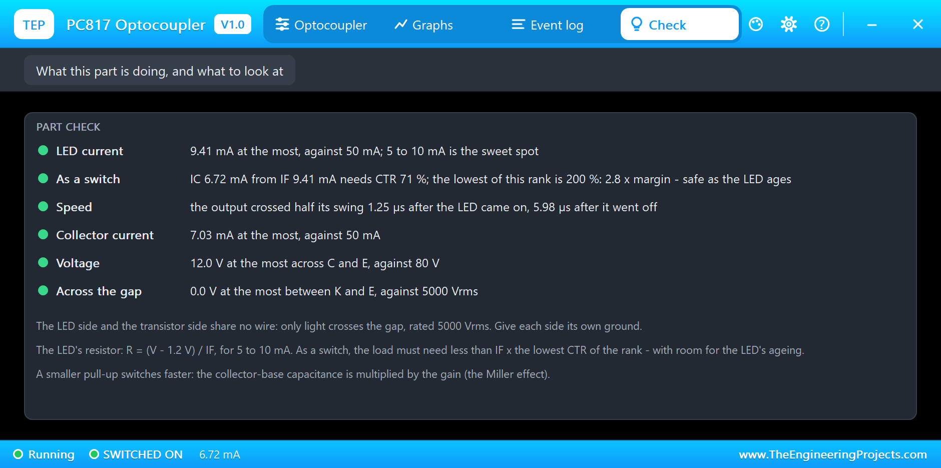
An infrared LED slowly loses brightness over tens of thousands of hours, and the CTR falls with it, by as much as half over the life of a product. A good design therefore leaves a margin: if the lowest CTR of the rank is 200 % and the load needs 71 %, the margin is 2.8 times, and the circuit will still switch when the LED has faded. Our Check page computes exactly this margin whenever the part is used as a switch.
Speed and the Load Resistor
A phototransistor is slow compared with a normal transistor. Its large collector-base junction, which collects the light, is also a large capacitor, and the transistor's gain multiplies that capacitance: the Miller effect. The PC817's datasheet gives a rise time of 4 µs and a fall time of 3 µs, but only with a 100 Ω load. With the 10k or 47k pull-up resistors that a microcontroller input usually has, the switching gets many times slower, and the turn-off is the slow edge: when the light stops, the base has nowhere to send its charge, so the transistor lets go only gradually.
The 4N35 has its base on pin 6, and that is the cure. A resistor of 100k to 1M from the base to the emitter gives the base charge a path out, so the transistor turns off much sooner. It also rejects electrical noise and the small dark current. The price is some CTR, because the resistor takes part of the photocurrent. The demo shows this with two identical 4N35s, one with its base open and one with 220k on it.
Where They Are Used
Optocouplers read 24 V sensors and switches into the inputs of industrial controllers, isolate the serial and MIDI lines of instruments, carry the feedback of mains power supplies across their safety barrier, detect the mains zero crossing for dimmers, drive the coils of relays on the popular relay modules, and protect a microcontroller from anything that happens on a long cable. The PC817 is on almost all of them, and the 4N35 is the classic choice where speed or the base pin matters.
Features of the PC817 Optocoupler Library for Proteus
- The real look, at true scale: the white DIP-4 PC817 with its anode dot and its printed rank, and the DIP-6 4N35, with our small TEP signature.
- The CTR rank: pick A, B, C, D or no rank in Edit Properties; the letter on the body changes on the stopped sheet and the model uses that rank.
- A real CTR curve: rising, peaking and falling with the LED current as in the datasheet, fitted to it at the test point.
- Switching times that follow the load: the junction charges make a big pull-up slow and a base resistor fast, and the pop-up measures the delays.
- The LED and its limits: its forward voltage, reverse voltage, current rating and burn-out.
- Linear, saturated and pulsed: it tells which one, recognises PWM on the LED, and shows averages while pulsed.
- A pop-up for each part: inside the package with the light across the gap, CTR against IF, graphs, an event log and a check page with the switching margin.
- A complete package: about 2.2 MB with the library, our Arduino UNO V4.0, our push button, resistors and LED and the demo, without the source code of the model.
The Optocouplers in Proteus
The devices are PC817TEP and OPTO4N35TEP in TEPOPTO.LIB, under Optoelectronics, Optocouplers, with the prefix U and the model TEPOPTO.DLL. Search PC817 or 4N35 in Pick Devices. They are drawn from above, pin 1 at the bottom left beside the anode dot: the PC817 has A and K at the bottom and E and C at the top; the 4N35 has A and K at the bottom, its third leg not connected, and E, C and B at the top.
The Properties
| Property | What it does |
|---|---|
| Part (VALUE) | PC817 or 4N35 |
| CTR rank (PC817) | no rank (50-600 %), A (80-160 %), B (130-260 %), C (200-400 %), D (300-600 %): printed on the body |
Download PC817 Optocoupler Library for Proteus
Click the button below to download PC817-Optocoupler-Library-for-Proteus-v1.0.zip (about 2.2 MB, without the source code of the models):
PC817 Optocoupler Library for Proteus V1.0- README.txt: installation, the demo, the wiring of an input and an output, troubleshooting and the limits.
- Proteus Library Files:
TEPOPTO.LIB, our push button, resistor and LED libraries, and ourArduinoV4TEP.LIB. - Proteus Model Files:
TEPOPTO.DLL, the DLLs of those parts andTEPARDUINO.DLL. - Arduino Code: the demo sketch.
- Proteus Simulation: the demo project, its HEX file and copies of the DLLs.
No Proteus yet? Read How to Download and Install Proteus 7 and 8. New to libraries? Follow How to Install a New Library in Proteus.
How to Install PC817 Optocoupler Library for Proteus
- Close Proteus and extract the whole zip file, for example to your Desktop.
- Copy the files from Proteus Library Files into the LIBRARY folder of Proteus.
- Copy the files from Proteus Model Files into the MODELS folder.
- Delete
TEPOPTO.IDXfrom the LIBRARY folder if it is there. - Start Proteus, press P and search for PC817.
Demo: Isolating an Arduino
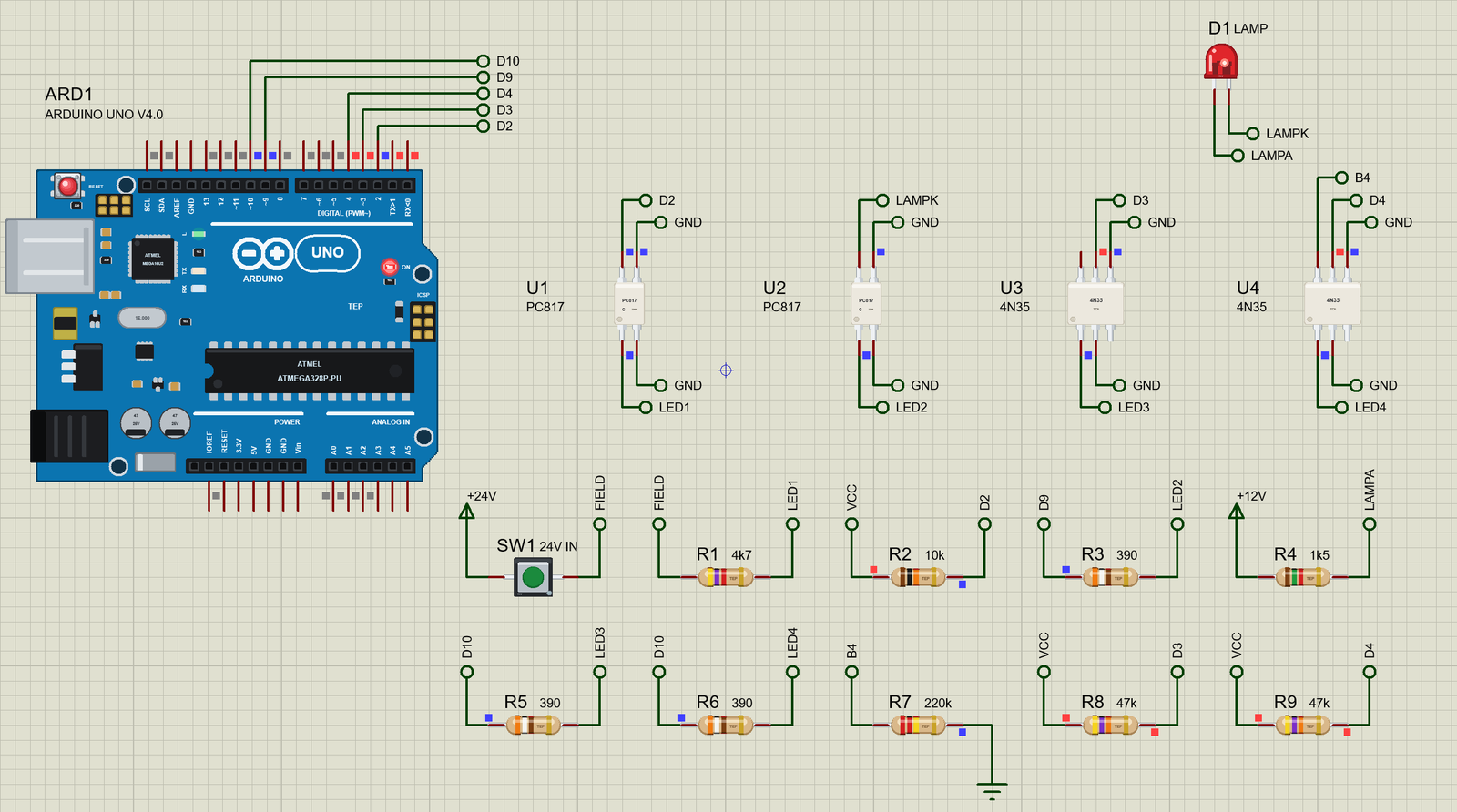
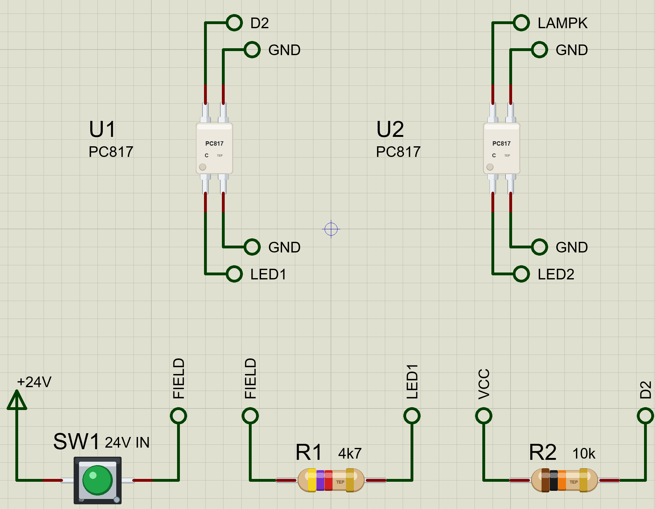
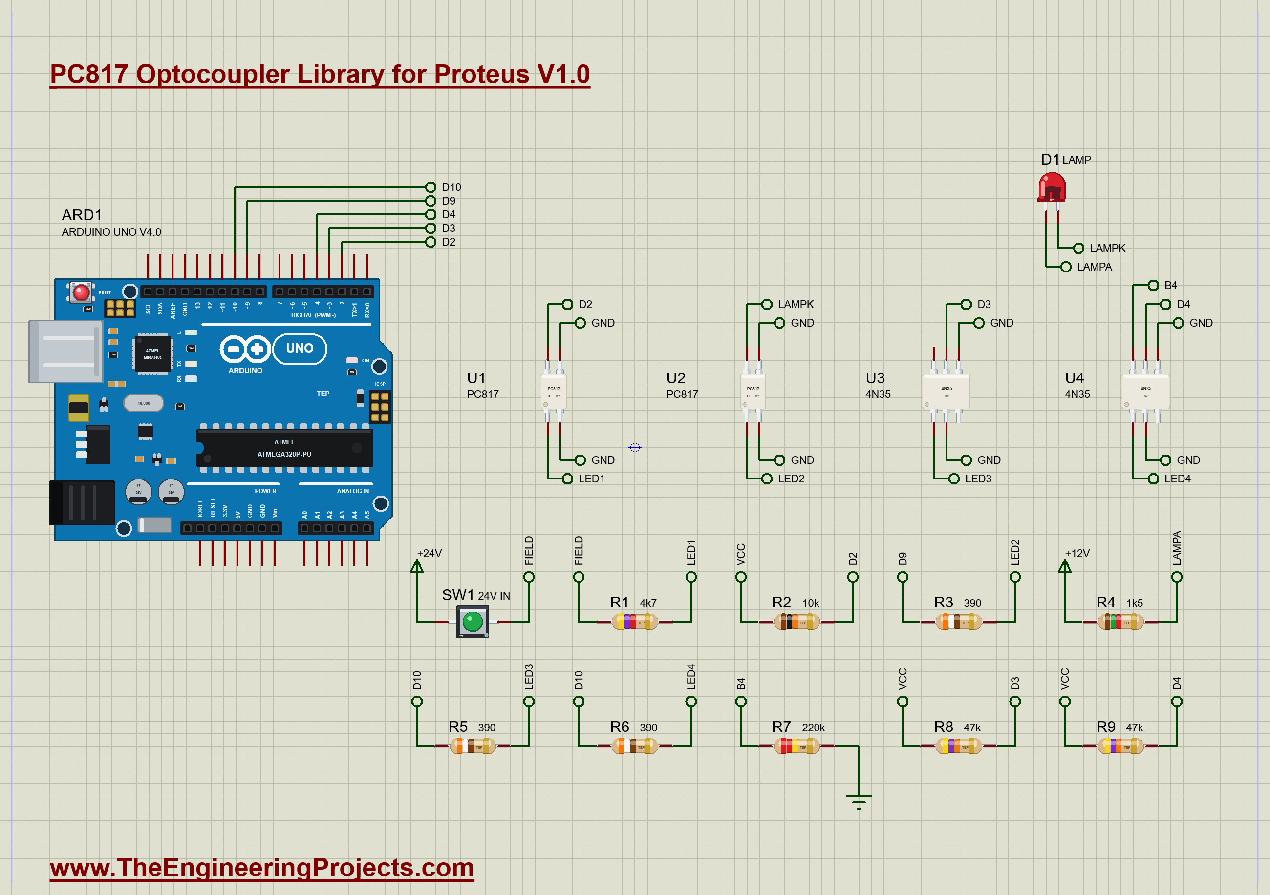
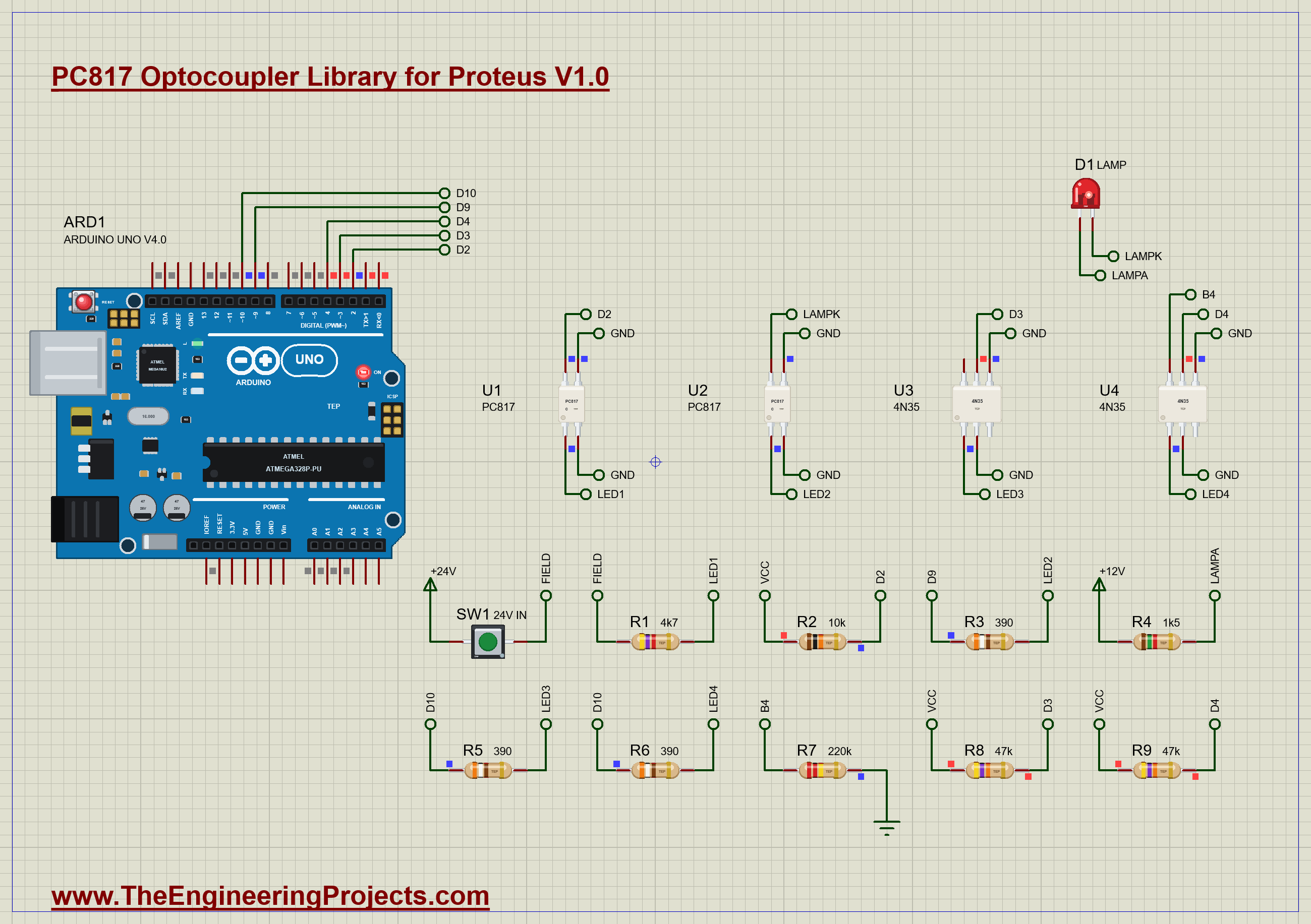
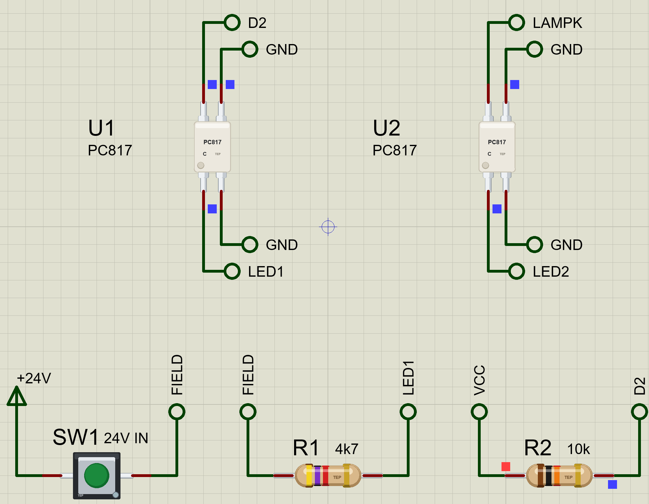
The demo has four optocouplers, each with a job. U1, a PC817, is a 24 V input: SW1, our push button, puts 24 V on its LED through R1 (4.7 kΩ), and its transistor pulls D2 down against R2 (10 kΩ). U2, another PC817, is an isolated output: D9 lights its LED through R3 (390 Ω), and its transistor switches a 12 V lamp, the red LED D1 with R4 (1.5 kΩ). U3 and U4 are 4N35s lit together from D10 through R5 and R6, pulling D3 and D4 down against 47 kΩ pull-ups; U4 has R7, 220 kΩ from its base to ground, and U3's base is open.
Open Optocoupler-Isolation-ArduinoUnoV4.pdsprj. It runs on our Arduino UNO Library for Proteus V4.0, with its built-in monitor, the same window as our TEP Serial Monitor Advance for Proteus. The switch is from our Push Button Library for Proteus and the lamp from our 5 mm LED Library for Proteus. The phototransistor inside is the same kind of NPN transistor as the ones in our Small Transistors Library for Proteus.
| Part | Connection | Job |
|---|---|---|
| U1 PC817, R1 4k7, R2 10k | SW1 from +24V to the LED; C to D2 | a 24 V input |
| U2 PC817, R3 390, R4 1k5, D1 | LED from D9; the lamp from +12V to C | an isolated 12 V output |
| U3 4N35, R5 390, R8 47k | LED from D10; C to D3; base open | the slow one |
| U4 4N35, R6 390, R9 47k, R7 220k | LED from D10; C to D4; 220k from B | the fast one |
In this simulation all four share one ground, because Proteus needs a reference for every node. In a real build the 24 V side of U1 and the 12 V side of U2 would each have their own ground, and only light would cross from them to the Arduino.
The Sketch
Every 3 s the sketch steps the lamp to its next level, 25, 75 and 100 %, with analogWrite on D9, and then times both 4N35s. It switches D10 and counts the microseconds until each output answers:
  digitalWrite(TEST, want == LOW ? HIGH : LOW);
  while ((t3 == NONE || t4 == NONE) && micros() - t0 < 5000) {
    const unsigned long dt = micros() - t0;
    if (t3 == NONE && digitalRead(OUT_3) == want) t3 = dt;
    if (t4 == NONE && digitalRead(OUT_4) == want) t4 = dt;
  }
The 24 V input needs one more thing. A push button bounces for a few milliseconds when it closes or opens, and an optocoupler passes every bounce faithfully to the Arduino. The sketch therefore accepts a change only once it has held for 20 ms:
  const bool raw = digitalRead(FIELD_IN) == LOW;
  if (raw != fieldRaw) {
    fieldRaw = raw;
    fieldSince = millis();
  }
  if (fieldRaw != fieldWas && millis() - fieldSince >= 20) {
Without those lines, a single press printed "24 V input: ON" and "OFF" five times in our first run.
Run the Demo
The 24 V Input
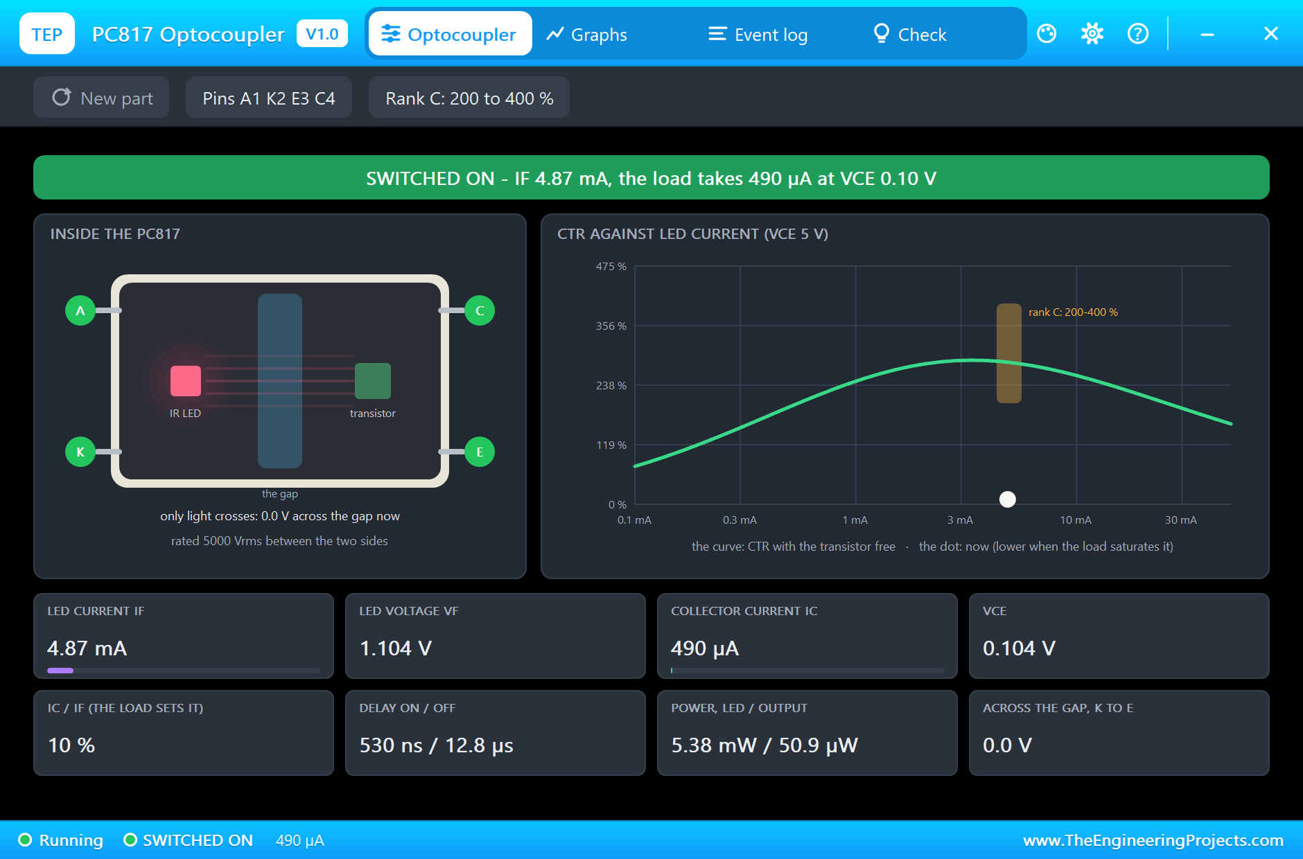
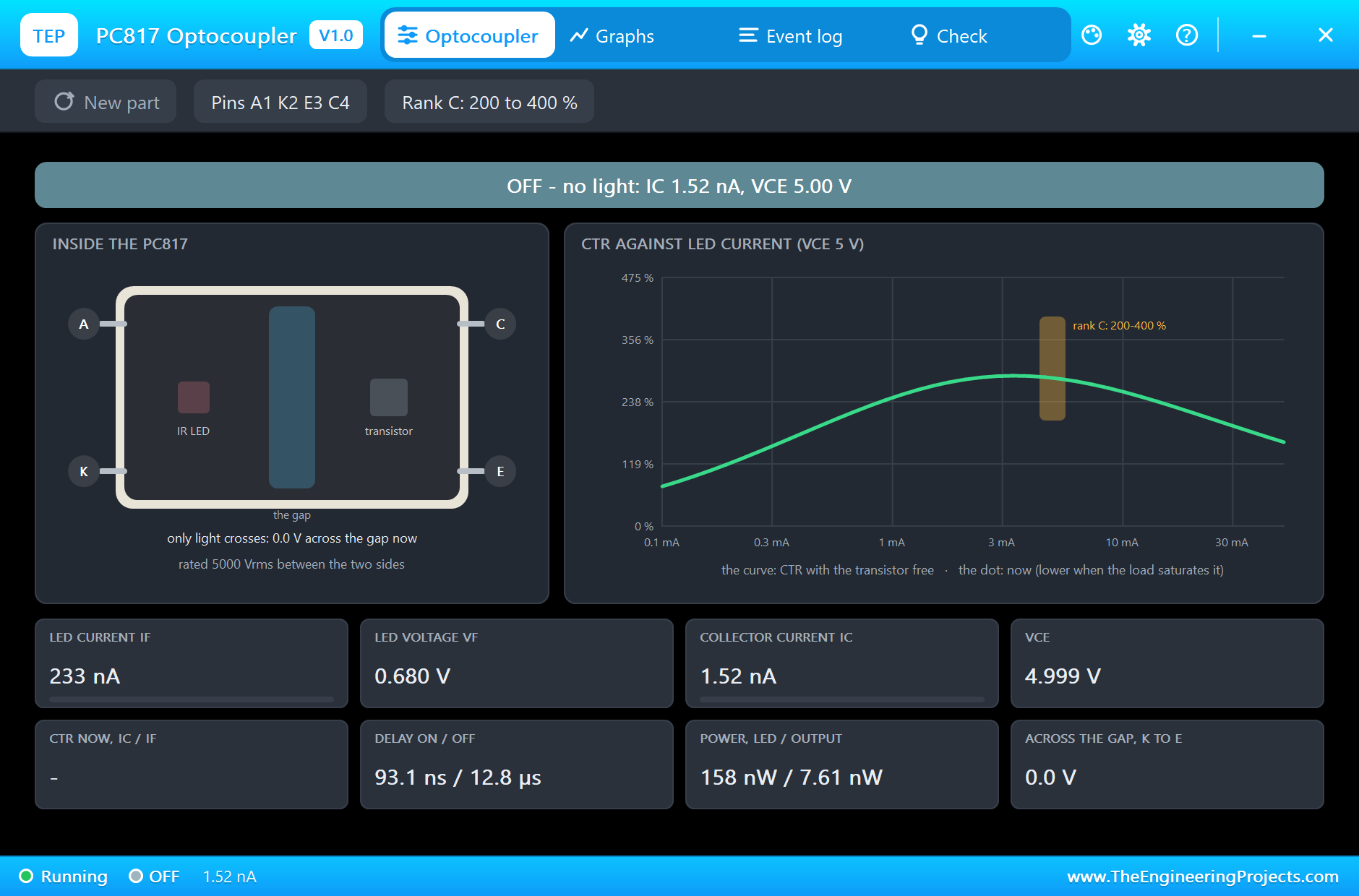
Press Run and hold SW1. 24 V through 4.7 kΩ puts 4.87 mA through U1's LED at 1.10 V, and the inside view shows it glowing, with the light crossing the gap. The transistor pulls D2 down to 0.10 V: the banner says SWITCHED ON, because the 10k pull-up only needs 490 µA, about 10 % of the LED current, far less than the 200 % that rank C guarantees. The dot sits well below the CTR curve, which is what a saturated switch looks like:
Here is the complete circuit running, with SW1 held:
Let go, and the light stops: the LED current falls to nothing and the output rises back to 5 V. The monitor prints the change once, thanks to the debounce:
The Isolated Lamp
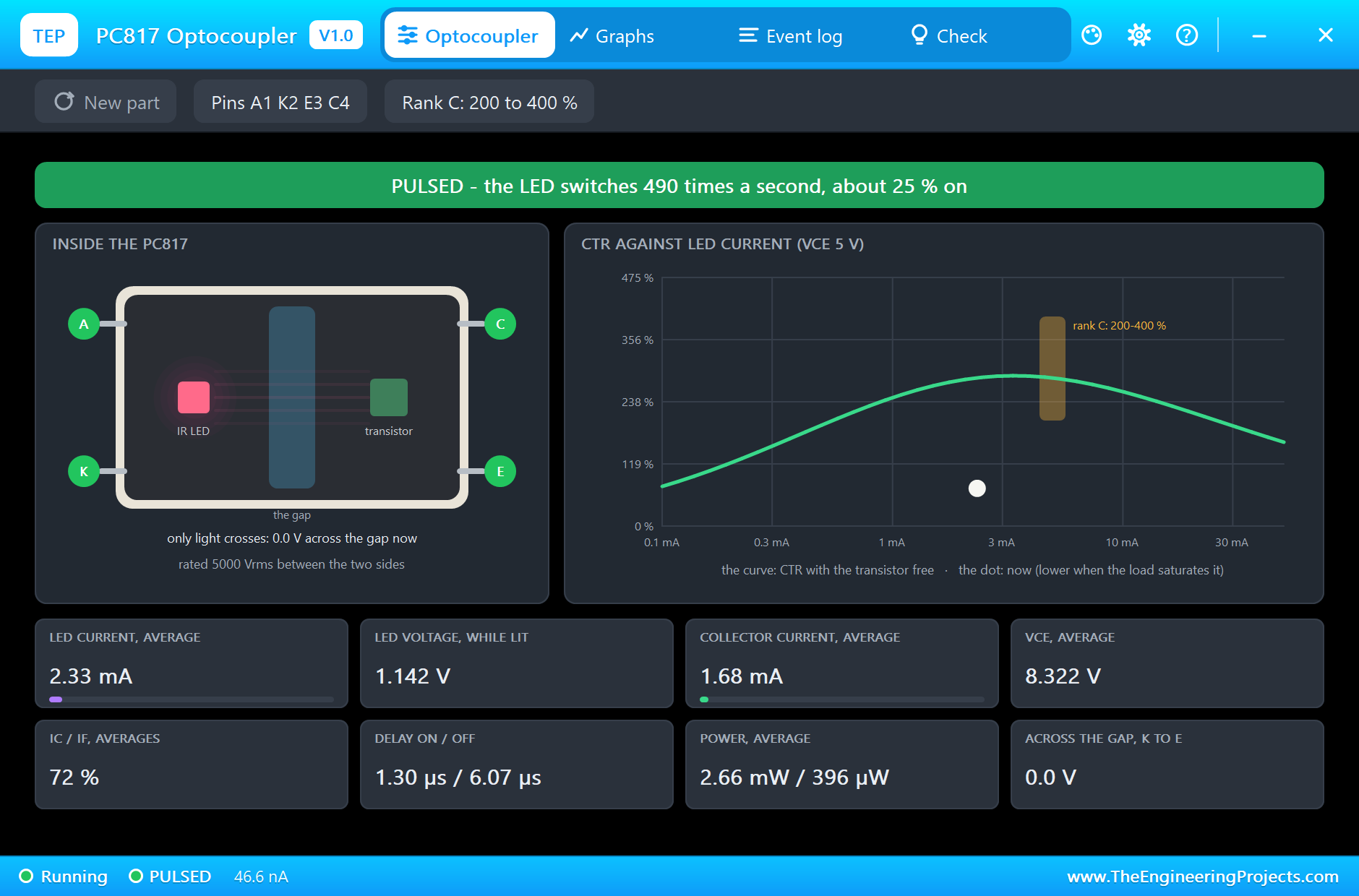
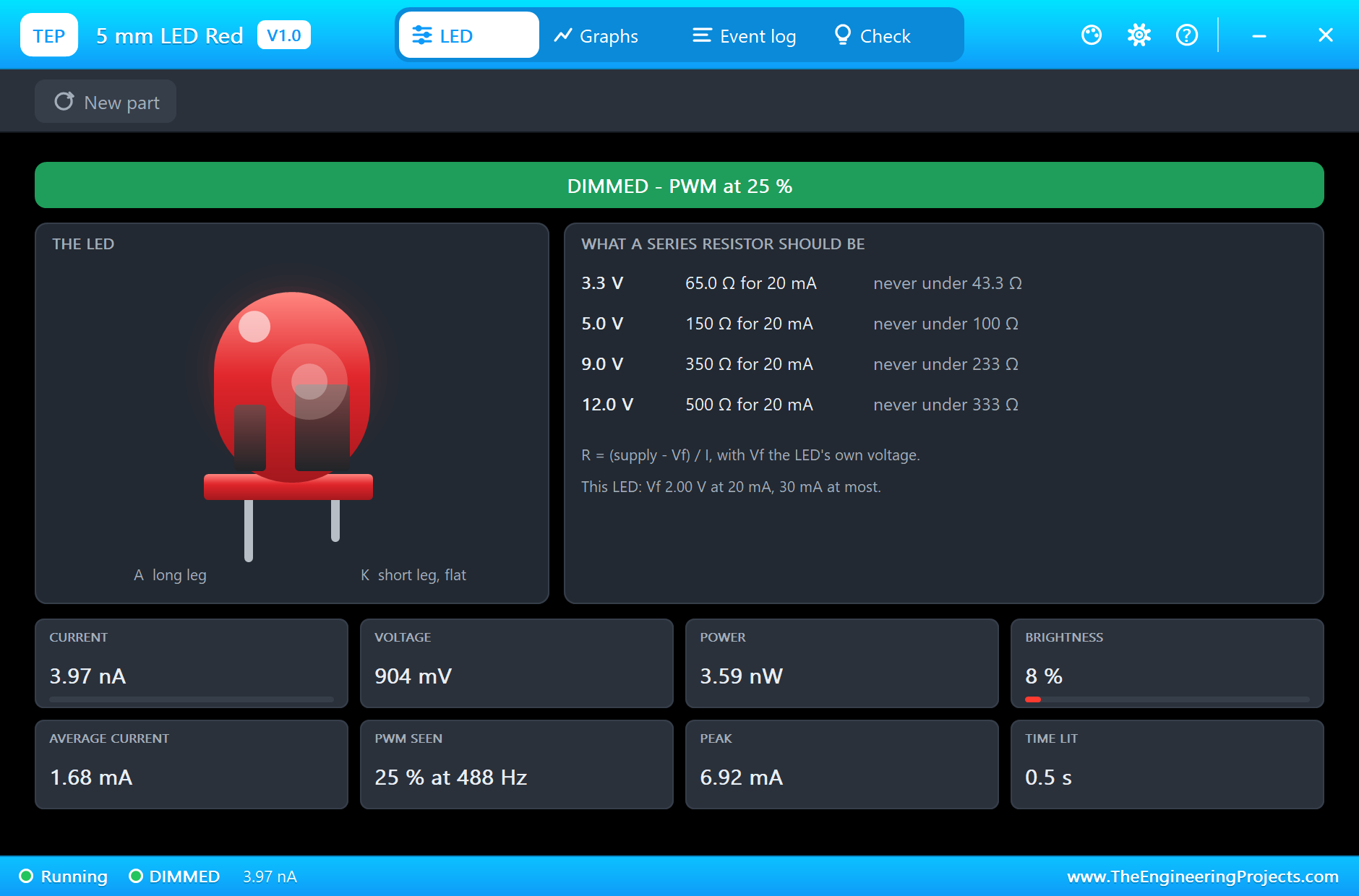
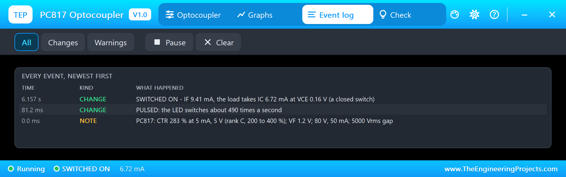
At the first step the lamp is at 25 %. U2's LED is switched by the PWM on D9, and the pop-up recognises it: PULSED at 490 Hz, about 25 % on. While pulsed, the cards and tiles show averages over the last 50 ms instead of a single instant: 2.33 mA in the LED and 1.68 mA in the lamp on average. The PC817 is fast enough for PWM at this frequency: its output follows the LED within a few microseconds. The lamp, our 5 mm LED, sees the same 25 % PWM and dims:
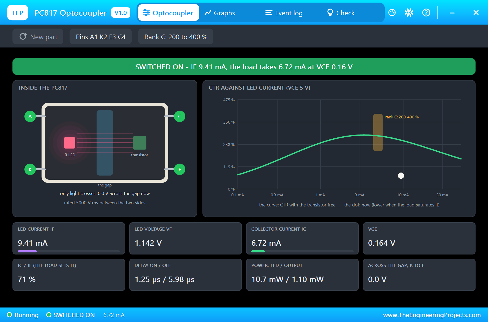
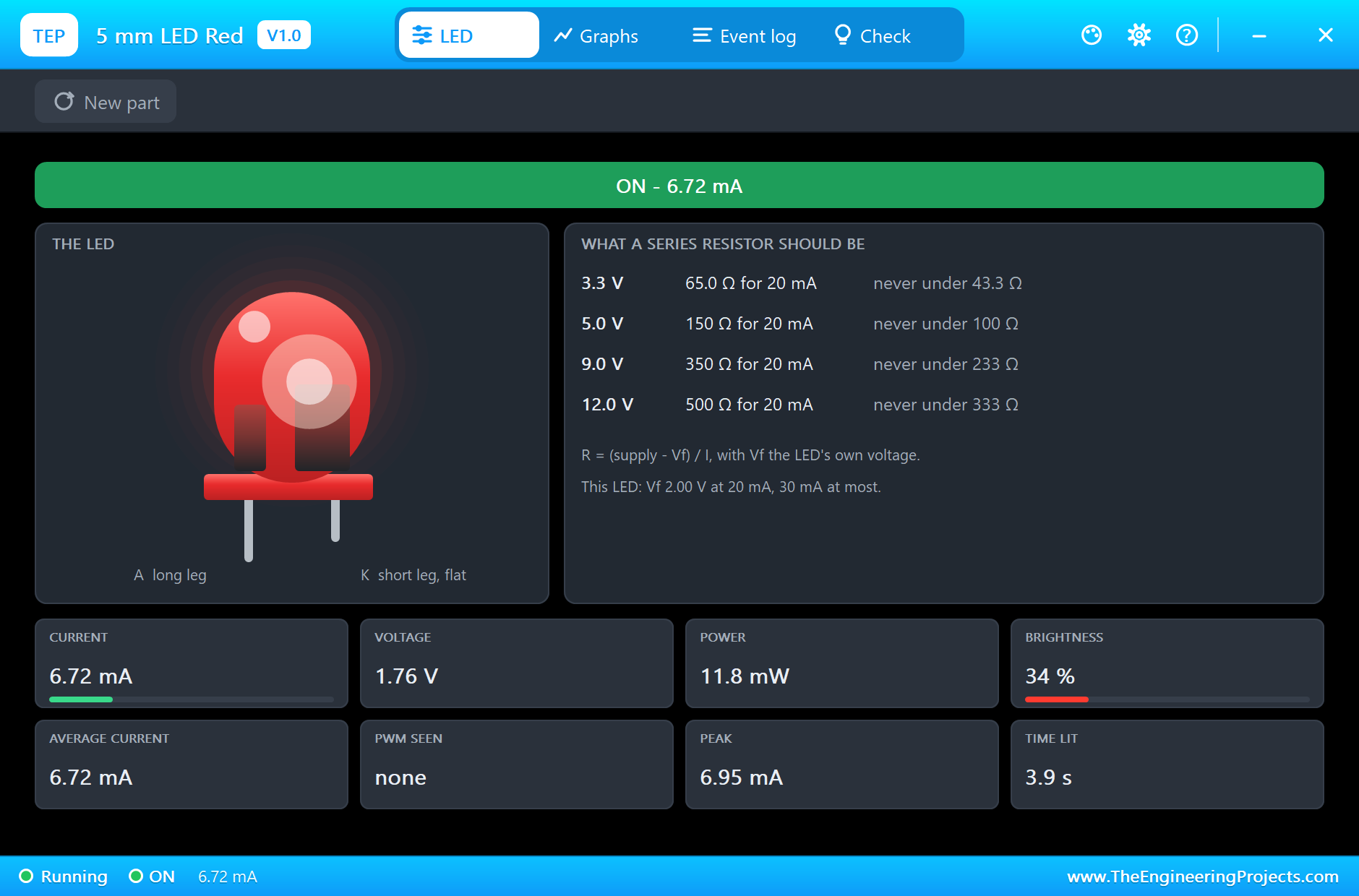
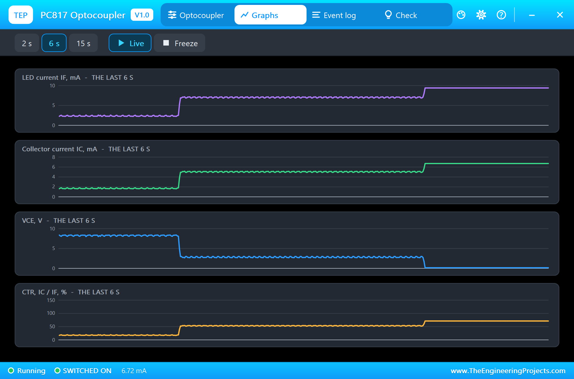
At 100 % the LED is on all the time: 9.41 mA in U2's LED switches 6.72 mA through the lamp with only 0.16 V across the transistor. The lamp takes 6.7 mA at 1.76 V. The Graphs page shows the three steps, 25 %, 75 % and fully on:
The Base Resistor
Now the 4N35s. Both turn on quickly, about 3 µs, because the LED's light charges the base fast. Turning off is another story. U3, with its base open, needs 138.6 µs after its LED goes dark before its output reaches half of its swing: the base charge can only leak away slowly, and the 47k pull-up makes the Miller effect large. U4, identical but with 220k from its base to ground, lets go in 21.9 µs: six times sooner, from one resistor:
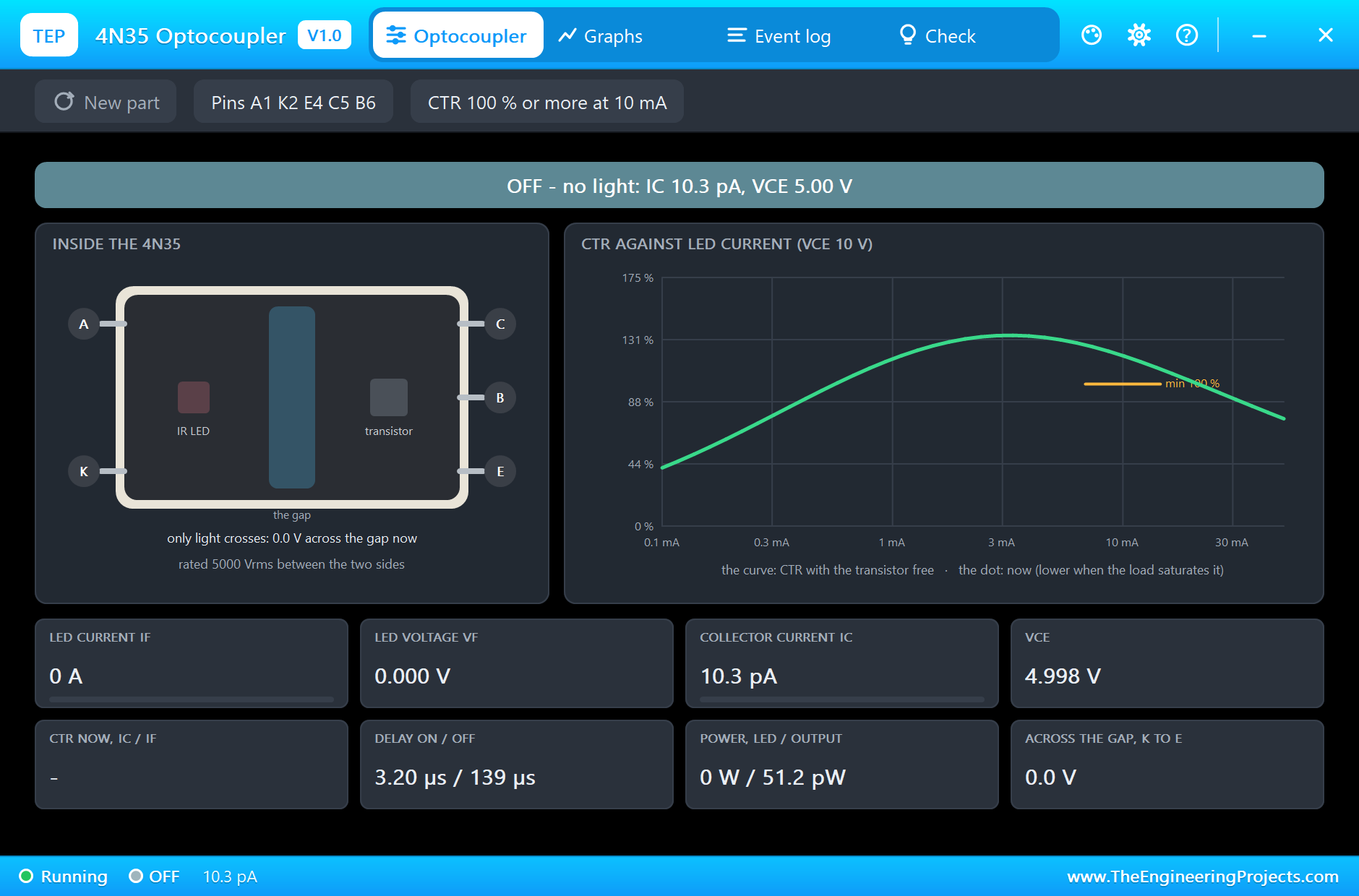
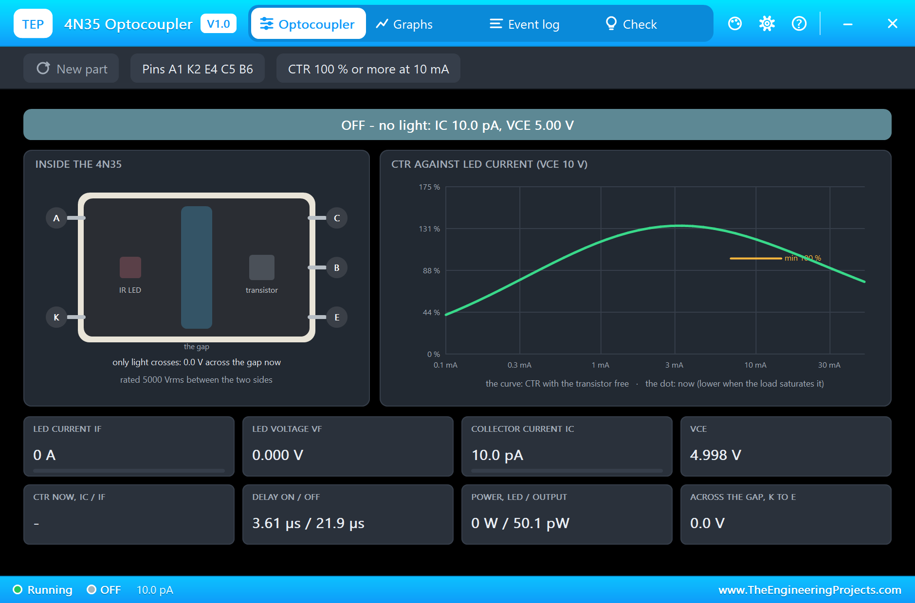
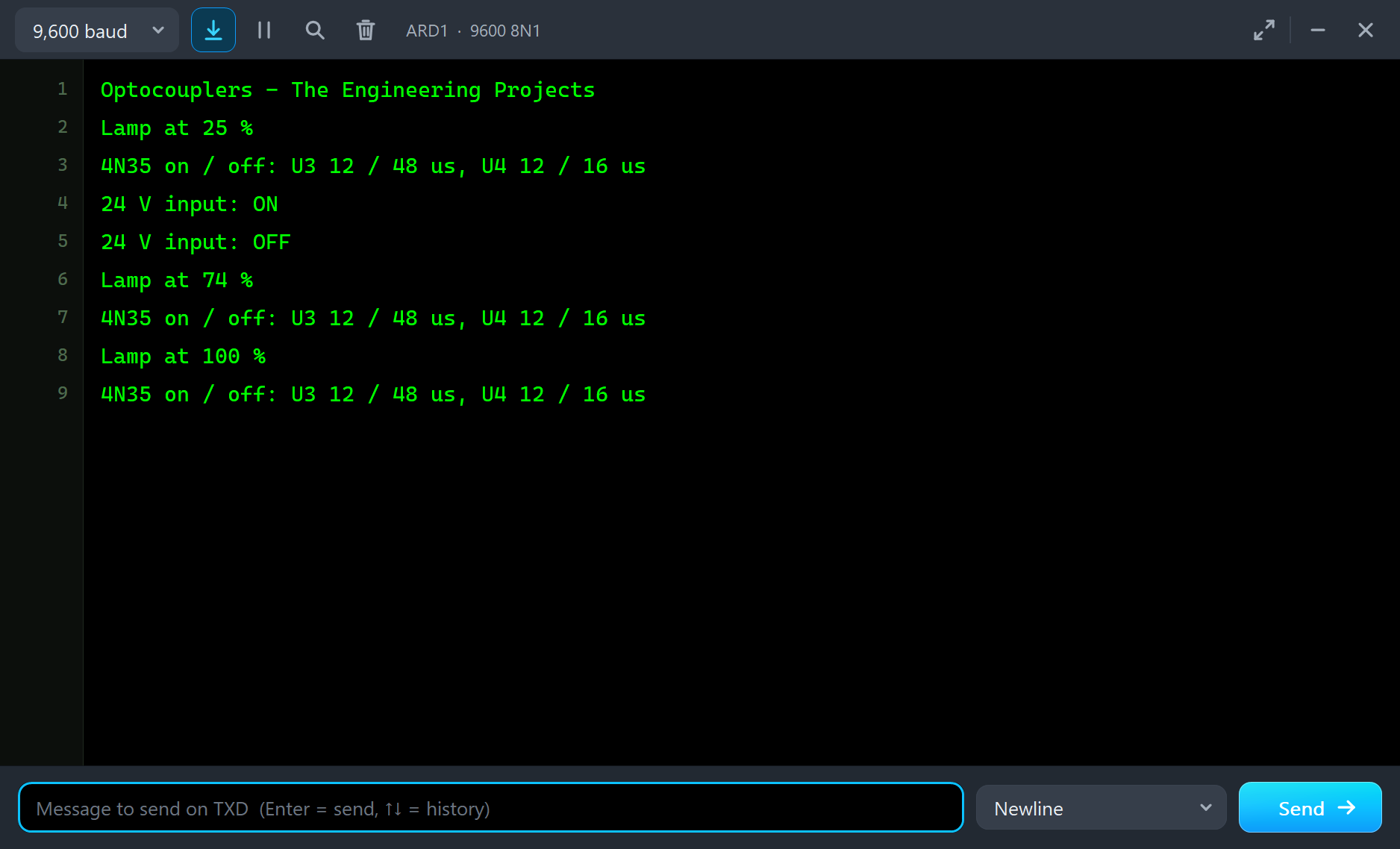
The Arduino sees the same difference: the monitor prints U3 12 / 48 µs and U4 12 / 16 µs. Its numbers are shorter than the pop-up's because they answer a different question. The pop-up measures the time to half of the output swing, 2.5 V. In this simulation the UNO's input already reads HIGH at about 1 V, and the loop that polls it checks only every few microseconds. Both agree on what matters: the open base is several times slower:
The Logs and the Check Pages
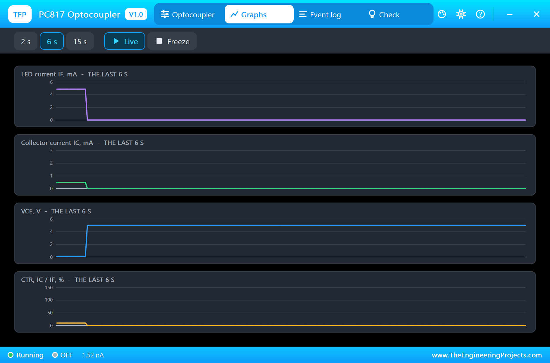
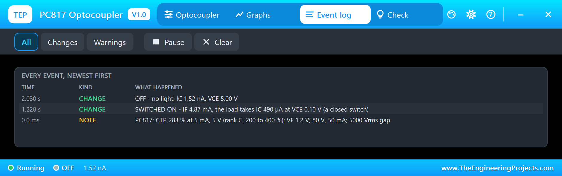
The Graphs page of U1 shows the LED current, the collector current and VCE for the press, and the Event log keeps the changes without flooding: U1 switched on and off; U2 pulsed, then switched on. A region is logged only when it holds for 20 ms, so a PWM signal is one line, not one per edge:
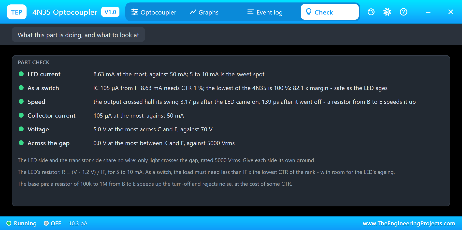
The Check pages turn the run into design advice. U2's says the lamp needed a CTR of 71 % and rank C guarantees 200 %: a 2.8 x margin, safe as the LED ages. U3's gives its speed and suggests the cure, a resistor from B to E, along with an 82 x margin for its light 105 µA load:
Try It Yourself
- Change U2's rank to A in Edit Properties, and see the margin shrink on its Check page.
- Change R8 and R9 to 10k, and watch both 4N35s get faster.
- Change R7 to 1M, and find the balance between speed and CTR.
- Raise R3 to 2.2k so U2's LED gets about 1.7 mA, and see the lamp leave saturation.
- Remove the debounce from the sketch, and count the bounces on the monitor.
Ideas to Extend the Demo
- Read several 24 V sensors on a row of PC817s, as a PLC input card does.
- Drive a relay coil on its own supply through a PC817 and a transistor.
- Build a zero-crossing detector for a mains dimmer with a 4N35.
- Isolate a serial line with two optocouplers, one each way.
Your Own Sketches
The demo sketch is in the zip file, and you can change it in the Arduino IDE. New to Arduino? Start with our Arduino Tutorial for Beginners. Export the compiled binary, and set the UNO's PROGRAM property to the new file. Our guide on How to get the HEX file from Arduino shows you where the file ends up.
Things to Know Before Using a Real Optocoupler
- Keep the grounds apart: joining them throws the isolation away.
- Size the LED resistor for 5 to 10 mA: R = (V - 1.2 V) / IF.
- Design with the lowest CTR of the rank: and leave a margin of two for the LED's ageing.
- Mind the speed: a smaller pull-up, or a base resistor on a 4N35, makes it faster.
- Protect the LED from reverse voltage: a diode across it for AC or reversible inputs.
Troubleshooting
- The output never switches: the LED is reversed, or IF times CTR is less than the load needs.
- It switches but slowly: a large pull-up; use a smaller one, or a base resistor on a 4N35.
- The input reads twice per press: the switch bounces; debounce it in software.
- LED BURNT: more than 50 mA for too long; use a bigger resistor.
- The part is not simulated:
TEPOPTO.DLLis missing from MODELS and from the project folder.
Limitations of the Simulation
- The 0.6 pF capacitance across the gap is left out, and so is the breakdown of the gap itself.
- CTR does not drift with temperature, and the LED does not age during a run.
- The charge stored while the transistor is saturated is an estimate: no datasheet figure fixes it, so the slowest turn-off times are a guide, not a promise.
- Arduino is a name of Arduino; this library is not made or endorsed by Arduino or Labcenter.
- Tested in Proteus 8.5 in November 2026 (the demo as shipped). Proteus 7 is not supported.
So, that was all about the PC817 Optocoupler Library for Proteus. I hope it helps you isolate your Arduino projects safely, choose the right CTR rank and see why one resistor on a base pin matters, all before you build. If you have any questions, ask in the comments and I will help you out. Till the next tutorial, take care and have fun!