Hello friends, I hope you all are doing great. Today, I am going to share the new TIP122 Darlington Library for Proteus. The TIP122 is the transistor almost every Arduino maker reaches for when a pin has to switch something big: a 12 V motor, a solenoid, an LED strip, a heater. It needs only a few milliamps on its base to carry amps through its collector, it comes in the sturdy TO-220 package that bolts onto a heatsink, and it costs very little.
TIP122 Darlington Library for Proteus
Latest version: V1.0 (November 2026, this tutorial)
Other component libraries: C945 Transistor · PC817 Optocoupler · Relay Module · Resistor · 5 mm LED · Designer Colour LED · Push Button · Active Buzzer · Electrolytic Capacitor · Ceramic Capacitor · Tantalum Capacitor · Film Capacitor · 1N4007 Diode · Zener Diode · Schottky Diode · Supercapacitor · Photodiode · RGB LED · Bridge Rectifier · Flashing LED · Bi-Colour LED · SMD LED · Slide Switch · Toggle Switch · Rocker Switch · Micro Limit Switch · Emergency Stop Switch · SMD Resistor · Power Resistor · Resistor Network · Potentiometer · Trimmer Potentiometer · Slide Potentiometer · NTC Thermistor · DIP Switch · Fuse · Passive Buzzer · Mini Speaker · 7-Segment Display · LED Bar Graph · IR / UV LED · Small Transistors · N-MOSFET · P-MOSFET · PC817 Optocoupler · Filament Bulb · Power LED · Voltage Regulator · SCR and TRIAC · Inductor · Toroid Inductor · Crystal
Helping Tools
- Serial Monitor Advance: a serial terminal window for the UART of your board
- Serial Monitor Expert: the serial monitor with extra debugging tools
- LCD Library for Proteus V3.0: 16x2, 20x4 and I2C LCDs to show your readings
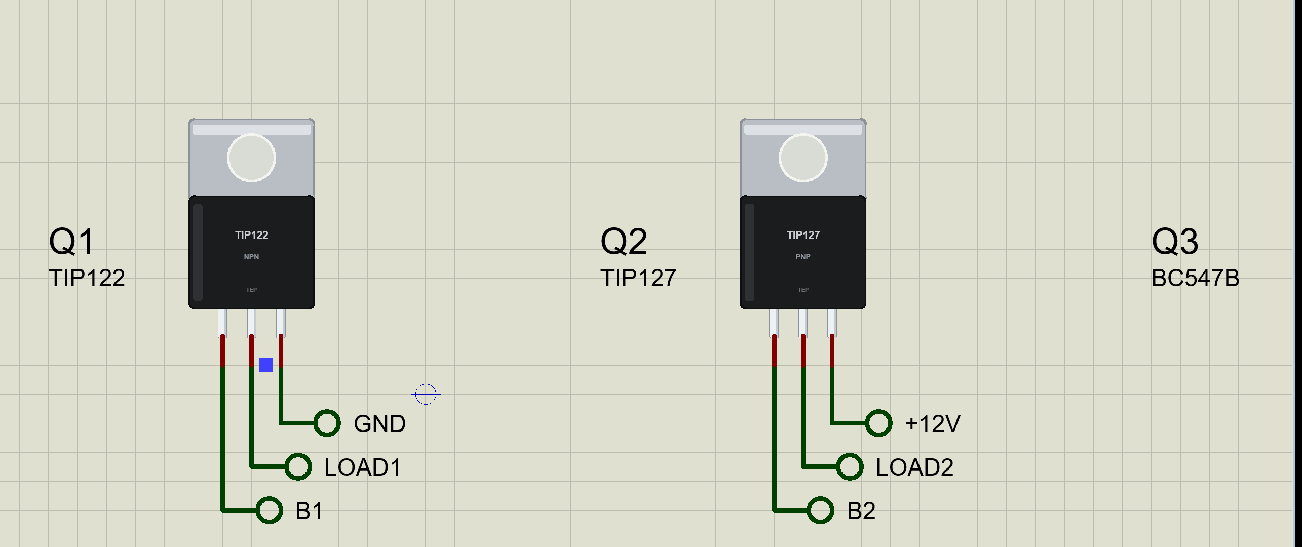
Our library has the TIP122 NPN Darlington and its PNP partner, the TIP127, both in TO-220 at true scale, with the metal tab and its mounting hole. Inside the model are two transistors, two resistors and a diode, exactly as on the real die, so the base needs about 1.3 V and the saturation voltage never drops below about 0.7 V, as on the bench. The junction heats through its heatsink, chosen by a property. The pop-up shows the region, what is conducting inside, the output curves and the temperature. The demo switches two 12 V loads from an Arduino: one on the low side with the TIP122, one on the high side with the TIP127.
NOTICE: Our team has put a lot of effort into these small parts: the bodies, the animation and the pop-ups are all our own design, and you get them free. Your feedback is the fuel that keeps us going, so please tell us what you think in the comments below or in the TIP122 Darlington board of our forum. And if our free libraries help you, you can buy us a coffee. So, let's get started with the TIP122 Darlington Library for Proteus:
What is a Darlington Transistor?
A Darlington pair is two bipolar transistors connected so that the first one's emitter current becomes the second one's base current. The small driver transistor amplifies the base current, and the large output transistor amplifies it again. The gains multiply: two transistors with a gain of 50 each make a pair with a gain of about 2,500. That is why a TIP122 can switch an amp from the few milliamps an Arduino pin gives through a 1k resistor.
The TIP122 puts the whole pair on one chip in one package, with two resistors added inside: about 8 kΩ across the driver's base-emitter and about 120 Ω across the output transistor's. They drain away leakage current so the part switches off cleanly. It also has a diode from the emitter to the collector, a side effect of how the chip is made, which conducts if the collector ever goes below the emitter.
| Feature | TIP122 | TIP127 |
|---|---|---|
| Type | NPN Darlington | PNP Darlington |
| Package | TO-220, pins B C E, the tab is C | TO-220, pins B C E, the tab is C |
| Ratings | 100 V, 5 A, 65 W on a heatsink | 100 V, 5 A, 65 W on a heatsink |
| hFE | 1000 or more at 3 A | 1000 or more at 3 A |
| Inside | Q1, Q2, 8k, 120 ohm, a C-E diode | the same, reversed |
| In the library | TIP122TEP | TIP127TEP |
The TO-220 Package
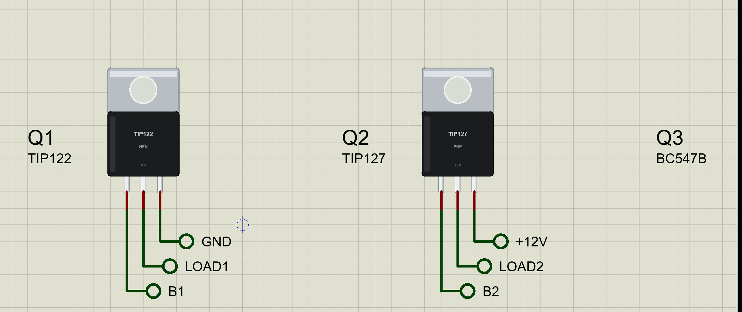
TO-220 is the package with the metal tab: a black body 10 mm wide and 9 mm tall, with a tab above it that has a 3.6 mm hole for a screw. The tab carries the heat from the chip to a heatsink, and it is connected to the collector, so on a grounded heatsink it needs an insulating pad and washer. Holding the part with the printed face towards you and the legs down, the pins are B C E from left to right for both the TIP122 and the TIP127.
Two Base-Emitter Drops
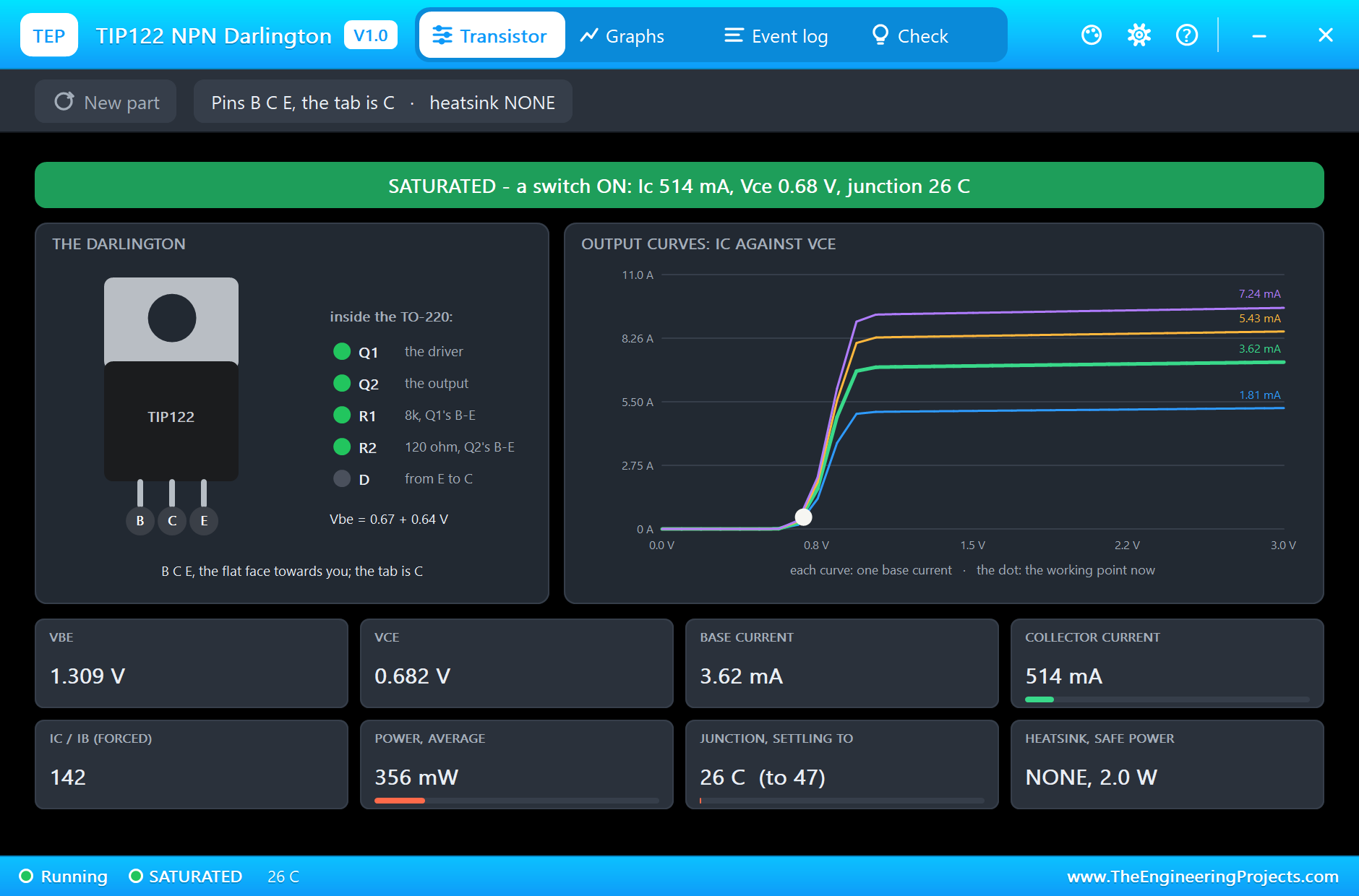
Since the base current flows through two base-emitter junctions in series, a Darlington needs about twice the voltage of a single transistor to turn on: around 1.2 to 1.4 V at moderate currents. Our pop-up shows the split: in the demo the TIP122's 1.31 V is 0.67 V across the driver and 0.64 V across the output transistor.
Why It Never Saturates Fully
A single transistor in saturation has only about 0.1 V across it. A Darlington cannot get that low: the output transistor's collector-emitter voltage is the driver's saturation voltage plus the output transistor's own base-emitter voltage. So a saturated TIP122 has at least about 0.7 V across it, and more at high currents, the datasheet allowing up to 2 V at 3 A. That voltage times the current is heat: at 3 A it is several watts, which is why the TIP122 is so often bolted to a heatsink, and why a logic-level MOSFET is the better switch for very high currents.
Junction Temperature and the Heatsink
The chip inside heats with the power it dissipates. How hot it gets depends on the thermal resistance from the junction to the air: 62.5 °C per watt for a bare TO-220, about 1.92 °C/W from the junction to the tab, and then whatever the heatsink adds. The junction must stay under 150 °C. Our model takes a HEATSINK property, NONE, SMALL or LARGE, and follows the junction temperature towards its settling value with a thermal time constant. The pop-up shows both the temperature now and where it is heading, and how much power keeps it under 150 °C.
| Heatsink | Junction to air | Power for 150 °C |
|---|---|---|
| NONE | 62.5 °C/W | 2.0 W |
| SMALL | 15 + 1.92 °C/W | 7.4 W |
| LARGE | 5 + 1.92 °C/W | 18 W |
Low Side and High Side
An NPN like the TIP122 goes on the low side: the load sits between the supply and the collector, and the emitter goes to ground. The base needs only a resistor from the pin, whatever the load's supply voltage. A PNP like the TIP127 goes on the high side: its emitter on the supply, the load between its collector and ground. That keeps the load grounded, which some loads need, but the base must be pulled all the way up to the supply to turn it off. A 5 V pin cannot do that for a 12 V supply, so a small NPN, here our BC547B, acts as a level shifter: the pin switches the BC547B, and the BC547B pulls the TIP127's base down.
The Diode Inside
The diode from the emitter to the collector is often mistaken for a flyback diode. It is not one: when a motor or relay coil connected to the collector is switched off, the collector voltage flies up, not down, and that diode never conducts. A real flyback diode goes across the coil itself. The built-in diode matters in bridges, where a transistor's collector can be pulled below its emitter; our model includes it, and the pop-up says when it conducts.
Where They Are Used
The TIP122 switches DC motors, solenoids, relays, LED strips, heaters and lamps from microcontrollers, and drives stepper motor coils in simple drivers. The TIP127 switches power on the high side and pairs with the TIP122 in H-bridges and push-pull stages for motors and audio. Both are in countless kits and robotics projects.
Features of the TIP122 Darlington Library for Proteus
- The real look, at true scale: TO-220 with the metal tab and its hole, the print and our small TEP signature.
- Two transistors inside: the driver and the output transistor with their resistors and the C-E diode, as on the real die.
- Real Darlington behaviour: about 1.3 V on the base, at least 0.7 V in saturation, a gain in the thousands.
- Junction temperature: through the heatsink you choose, with the settling value, a warning at 150 °C and failure at 175 °C.
- Converges like SPICE: the inner node solved inside, the junctions limited between steps.
- A pop-up for each part: the region, what conducts inside, the output curves, eight live values, graphs, an event log and a check page.
- A complete package: about 2.2 MB with the library, our Arduino UNO V4.0, our power resistors, resistors and BC547B and the demo, without the source code of the model.
The TIP122 and TIP127 in Proteus
The devices are TIP122TEP and TIP127TEP in TEPTIP.LIB, under Transistors, Darlington, with the prefix Q and the model TEPTIP.DLL. Search TIP122 or TIP127 in Pick Devices. Pins 1, 2 and 3 are B, C and E.
The Properties
| Property | What it does |
|---|---|
| Part (VALUE) | TIP122 or TIP127 |
| Heatsink | NONE, SMALL or LARGE: sets how fast the junction heats and how hot it settles |
Download TIP122 Darlington Library for Proteus
Click the button below to download TIP122-Darlington-Library-for-Proteus-v1.0.zip (about 2.2 MB, without the source code of the models):
TIP122 Darlington Library for Proteus V1.0- README.txt: installation, the demo, the heatsink settings, troubleshooting and the limits.
- Proteus Library Files:
TEPTIP.LIB, our resistor, power resistor and small transistor libraries, and ourArduinoV4TEP.LIB. - Proteus Model Files:
TEPTIP.DLL, the DLLs of those parts andTEPARDUINO.DLL. - Arduino Code: the demo sketch.
- Proteus Simulation: the demo project, its HEX file and copies of the DLLs.
No Proteus yet? Read How to Download and Install Proteus 7 and 8. New to libraries? Follow How to Install a New Library in Proteus.
How to Install TIP122 Darlington Library for Proteus
- Close Proteus and extract the whole zip file, for example to your Desktop.
- Copy the files from Proteus Library Files into the LIBRARY folder of Proteus.
- Copy the files from Proteus Model Files into the MODELS folder.
- Delete
TEPTIP.IDXfrom the LIBRARY folder if it is there. - Start Proteus, press P and search for TIP122.
Demo: Low-Side and High-Side 12 V Switches
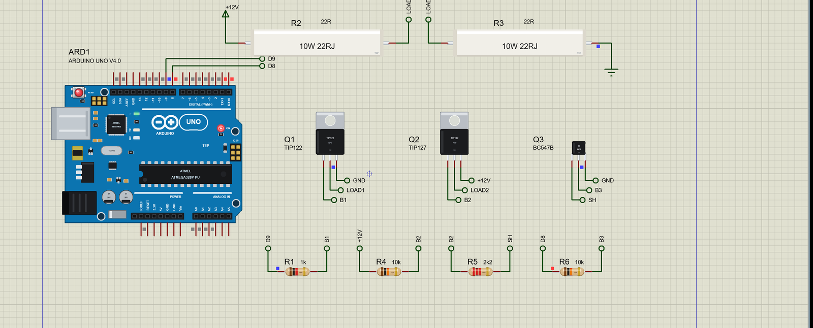
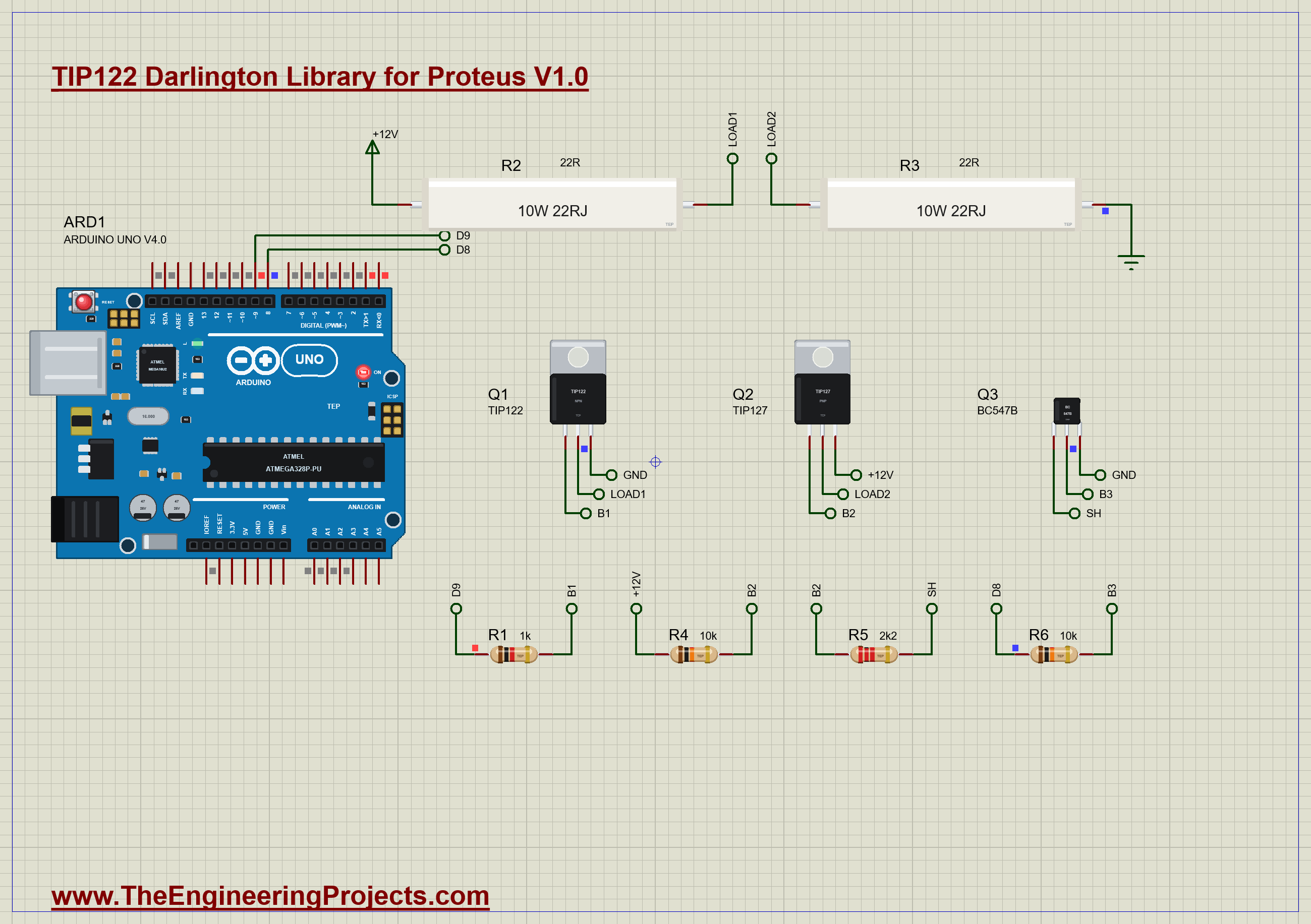
Two 12 V loads, each one of our 10 W power resistors at 22 Ω, about half an amp. Q1, the TIP122, switches the first on the low side: D9 drives its base through R1, 1k, and the load R2 sits between +12 V and its collector. Q2, the TIP127 with a SMALL heatsink, switches the second on the high side: its emitter on +12 V, the load R3 from its collector to ground. R4, 10k, pulls its base up to +12 V, and Q3, a BC547B driven from D8 through R6, pulls it down through R5, 2k2. Open TIP122-TIP127-Darlington-ArduinoUnoV4.pdsprj. It runs on our Arduino UNO Library for Proteus V4.0, with its built-in monitor, the same window as our TEP Serial Monitor Advance for Proteus. The loads are from our Power Resistor Library for Proteus, the BC547B from our Small Transistors Library for Proteus and the resistors from our Resistor Library for Proteus.
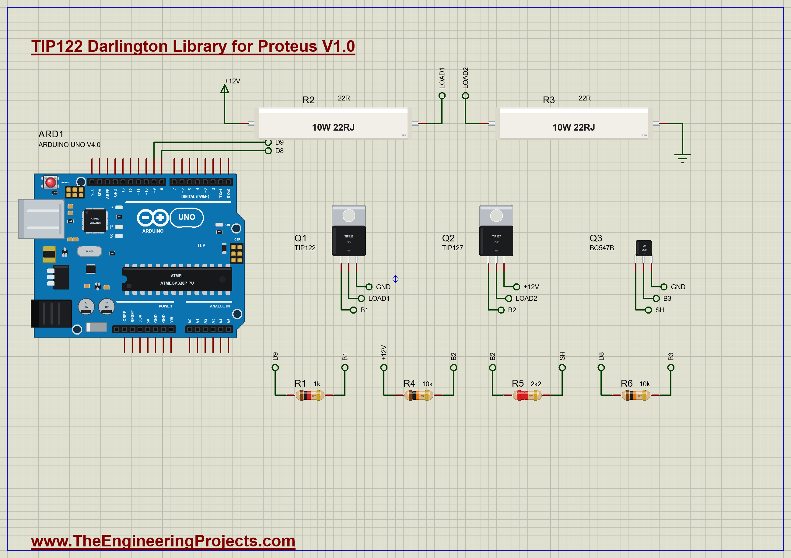
| Part | Connection | Job |
|---|---|---|
| Q1 TIP122, R1 1k | B from D9, C to LOAD1, E to GND | the low-side switch |
| R2 22 ohm 10 W | +12V to LOAD1 | load 1 |
| Q2 TIP127, SMALL heatsink | E on +12V, C to LOAD2 | the high-side switch |
| R3 22 ohm 10 W | LOAD2 to GND | load 2 |
| R4 10k, R5 2k2 | B2 up to +12V, B2 down to Q3 | its base pull-up and drive |
| Q3 BC547B, R6 10k | B from D8, C pulls B2 down | the level shifter |
The Sketch
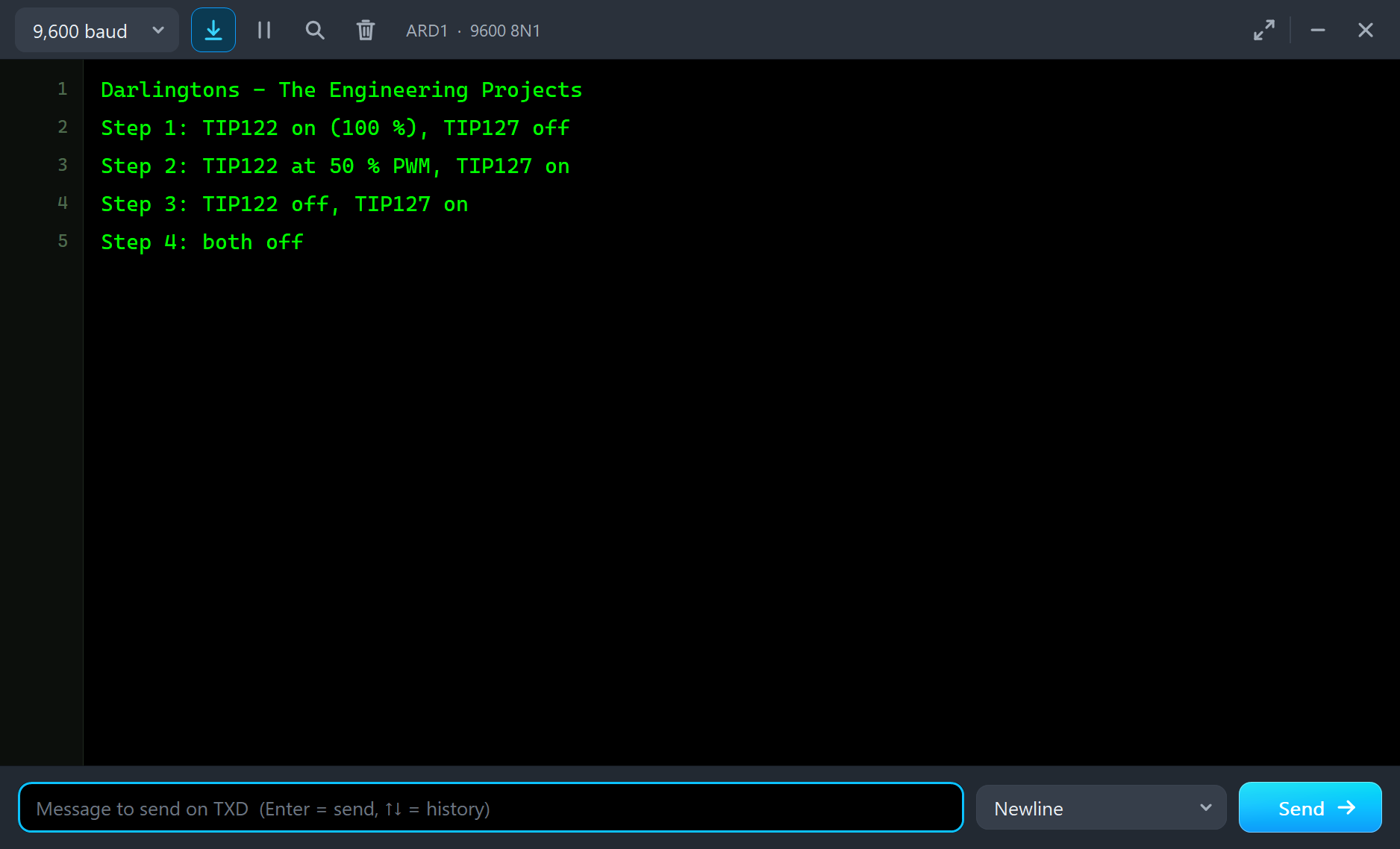
The sketch steps through four states, 2.5 s each, from a table: the TIP122's PWM duty and whether the TIP127 is on:
const byte DUTY[4] = {255, 128, 0, 0};
const bool HIGH_ON[4] = {false, true, true, false};
At each step it sets the TIP122's duty with analogWrite and switches the BC547B, and with it the TIP127:
    analogWrite(LOW_SIDE, DUTY[step]);
    digitalWrite(HIGH_SIDE, HIGH_ON[step] ? HIGH : LOW);
Note the logic of the high side: D8 HIGH turns the BC547B on, which pulls the TIP127's base down and turns it on. The level shifter inverts nothing for the user: HIGH still means on.
Run the Demo
Press Run. In the first step the TIP122 is on. Its pop-up says SATURATED: 3.62 mA into its base, 514 mA through the load, 0.68 V across it and 1.31 V on its base, 0.67 V for the driver and 0.64 V for the output transistor. All five parts inside light up except the diode. It dissipates 356 mW, and with no heatsink its junction is heading for 47 °C. On the curves, the dot sits on the steep part at the left: saturation. With 3.62 mA, the TIP122 could carry several amps; the 22 Ω load limits it to half an amp:
Here is the complete circuit, truly running:
The High Side
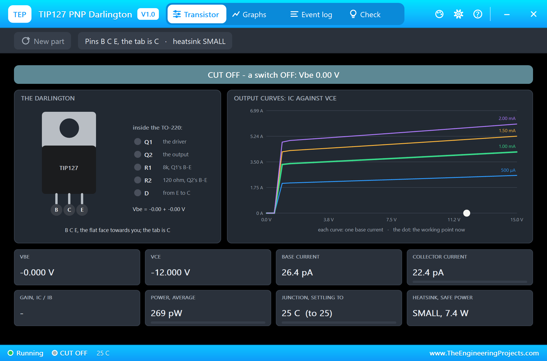
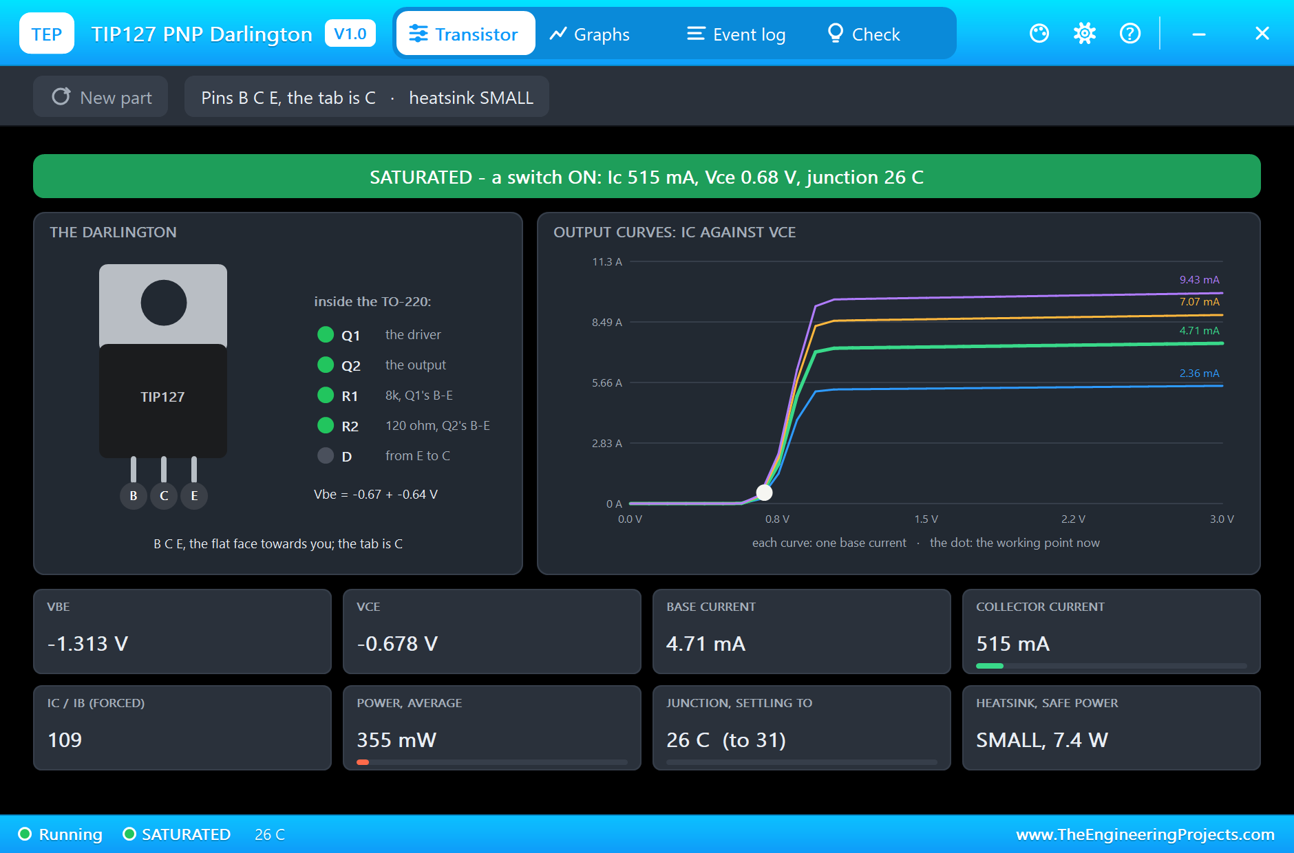
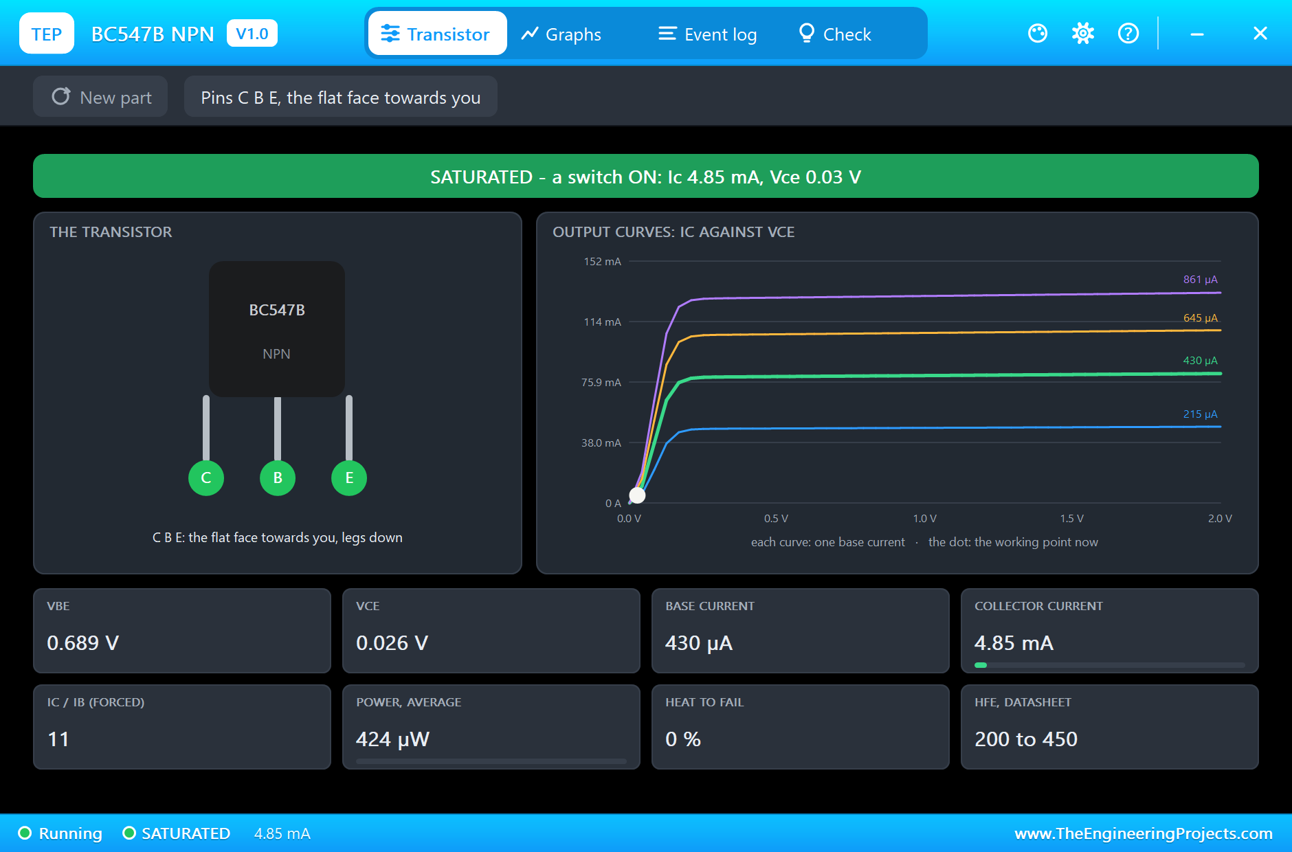
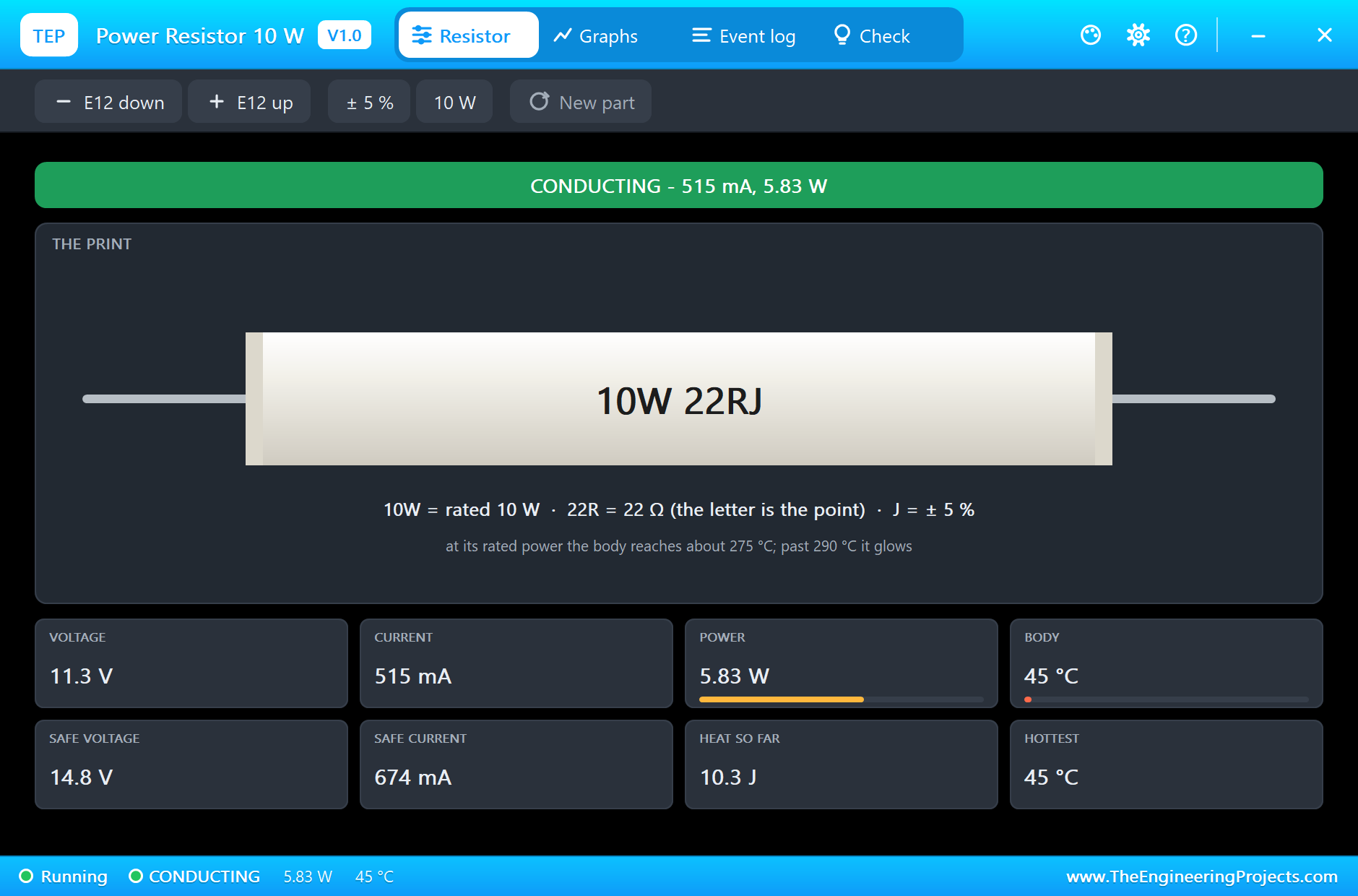
In the second step the TIP127 switches on. The BC547B is saturated, pulling 4.85 mA through R5; that current comes out of the TIP127's base, which saturates it too: 515 mA into its load, -0.68 V across it, 355 mW. On its SMALL heatsink, its junction heads for only 31 °C. The load itself takes 5.83 W of its 10 W rating:
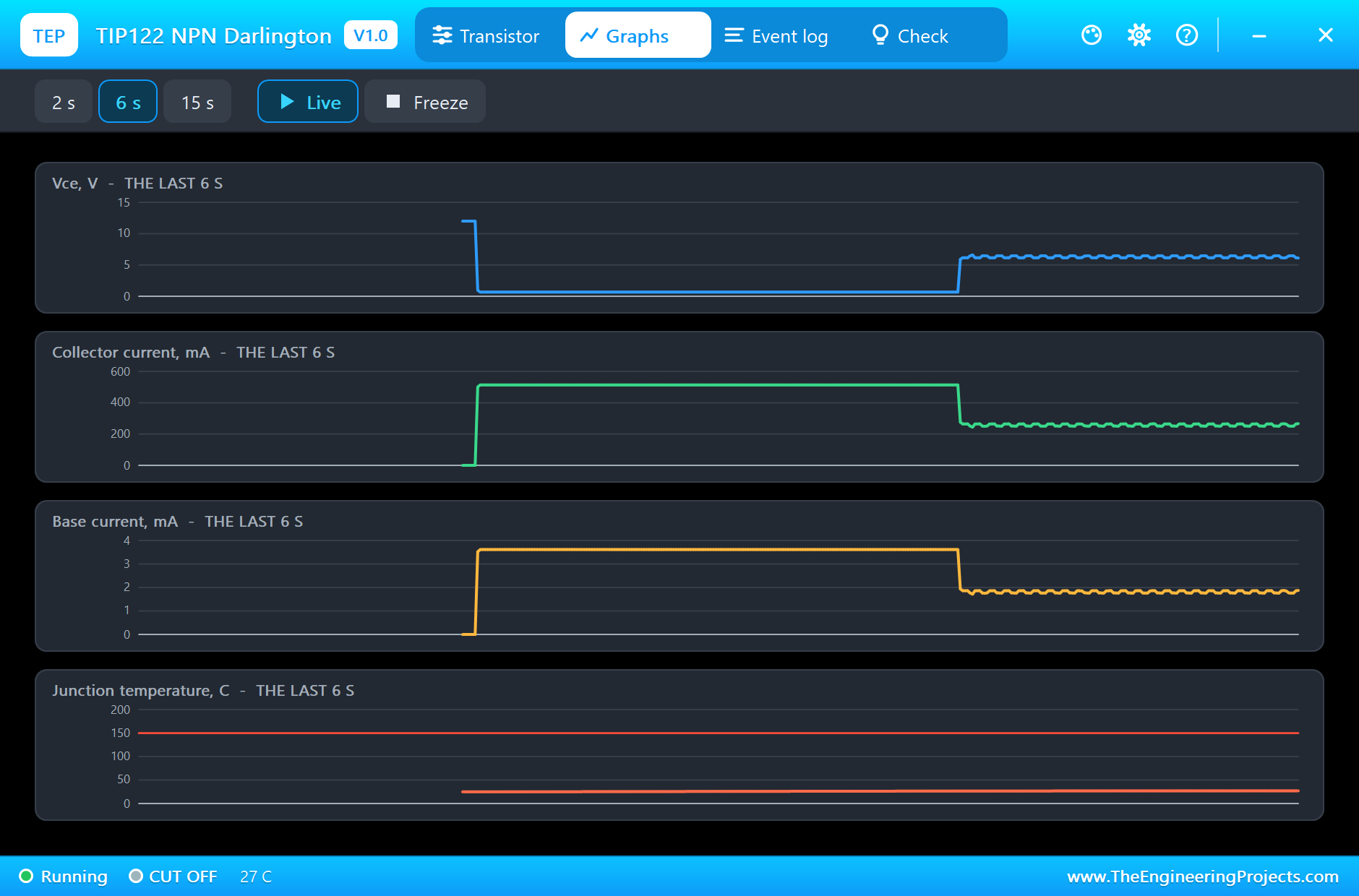
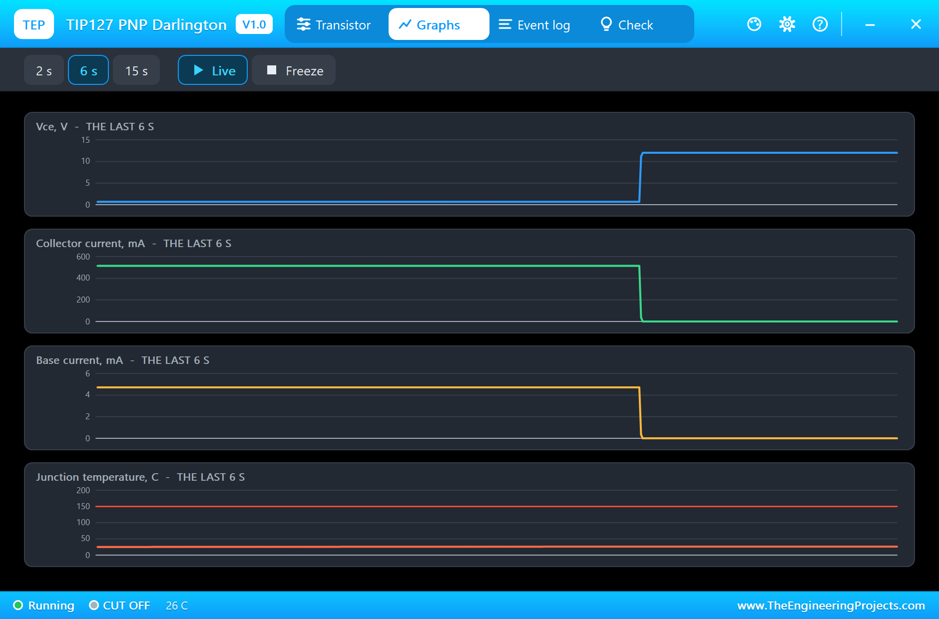
In the same step the TIP122 switches at 50 % PWM. Its Graphs page shows the jump from cut off to half an amp in the first step, and then the averaged current and base current at half their values as the PWM runs:
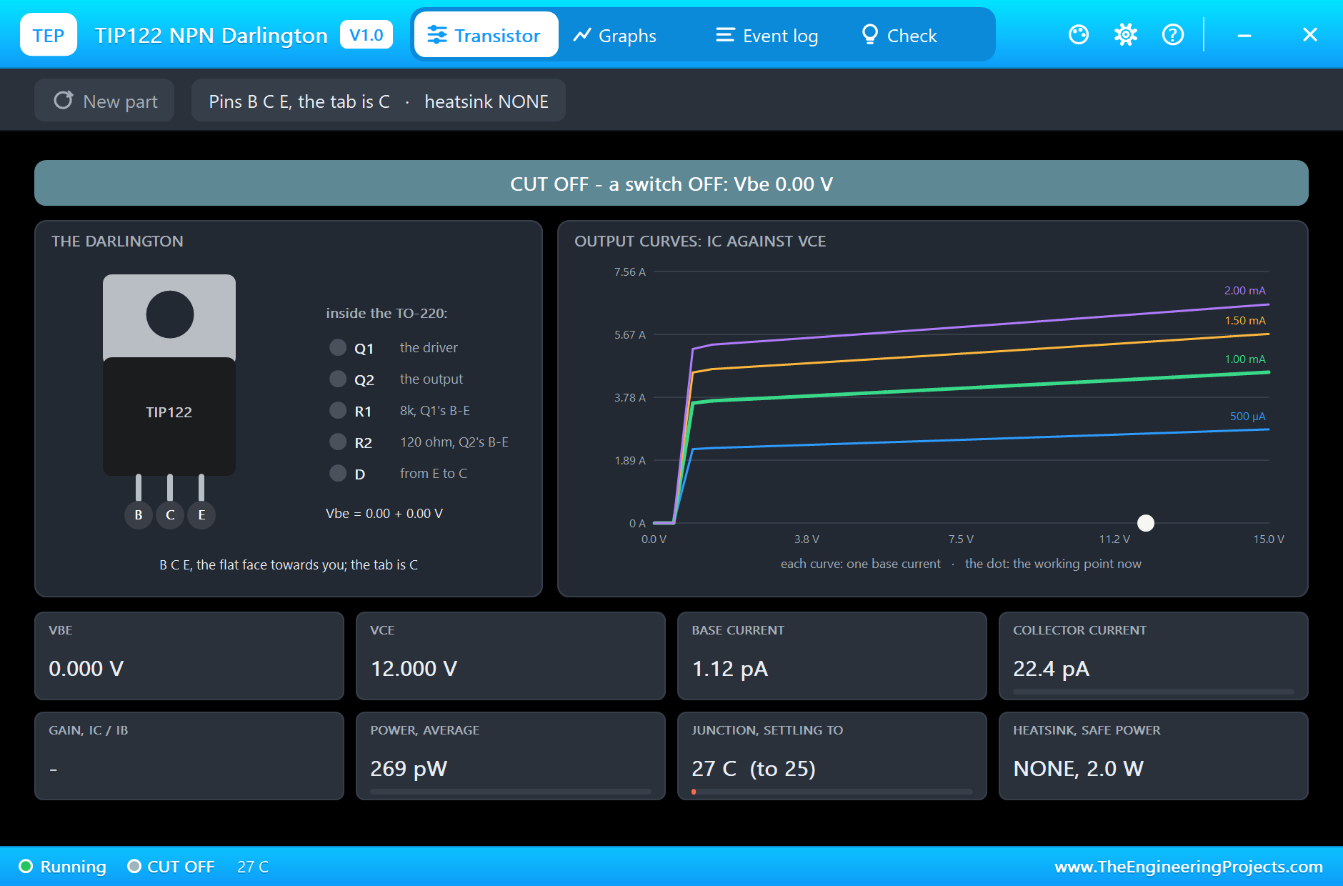
In the third step the TIP122 is off: cut off, with the full 12 V across it and no current:
The Log and the Check Pages
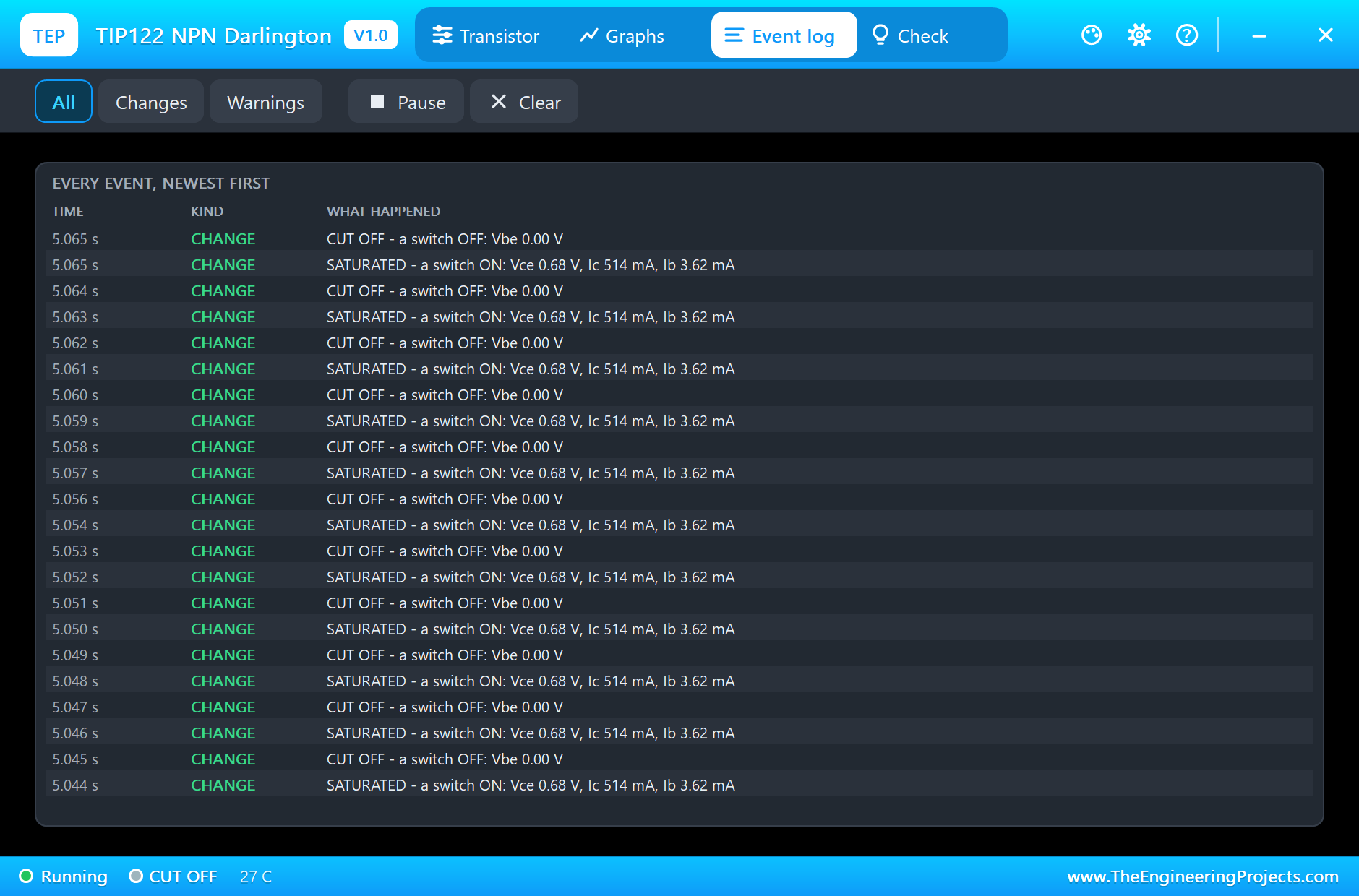
The Event log names every region change with its numbers, and the monitor prints each step of the sketch:
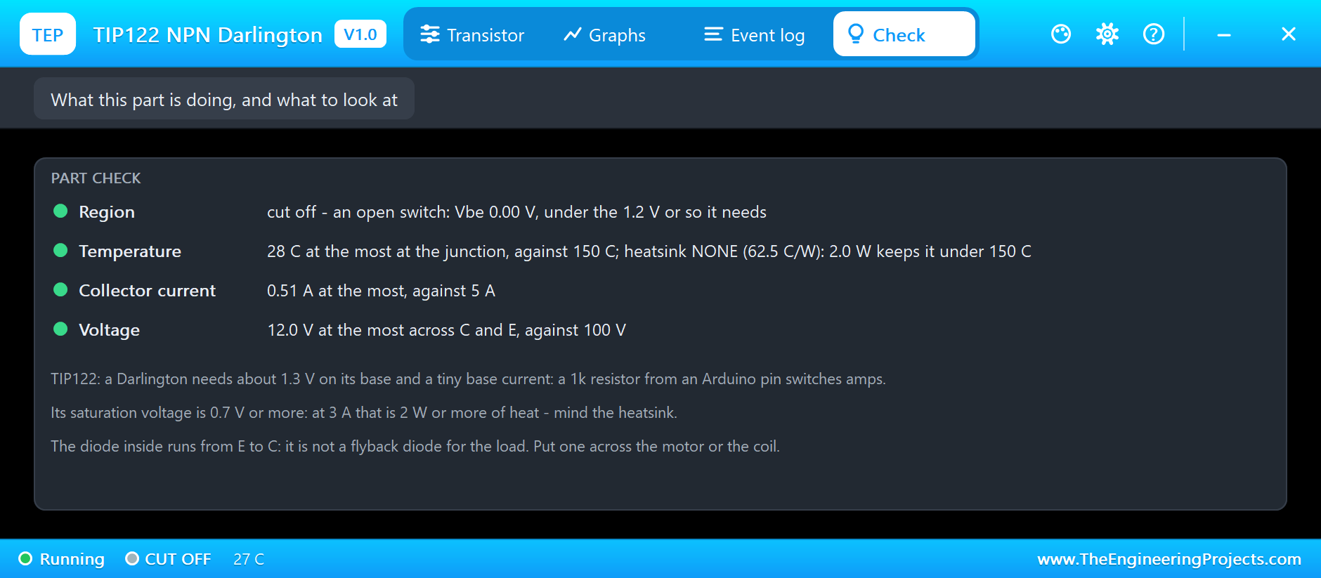
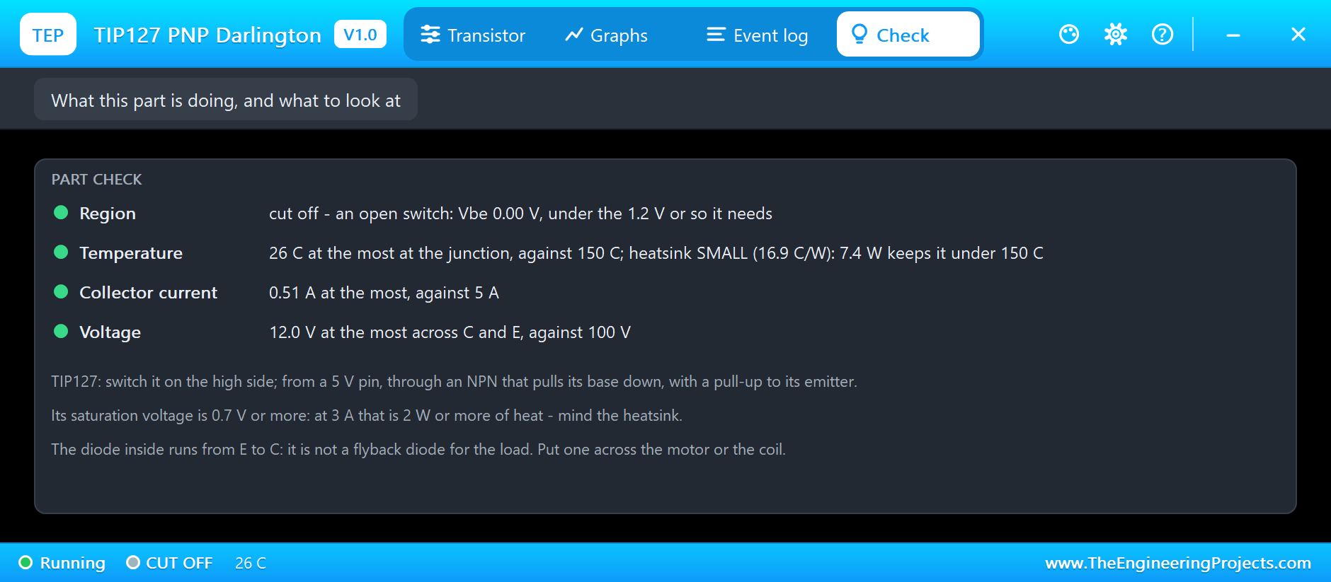
The Check pages judge the region, the junction temperature against 150 °C with the heatsink in use, the collector current against 5 A and the voltage against 100 V. Both parts are well inside their limits here:
Try It Yourself
- Change the loads to 4.7 Ω, and watch the current, the saturation voltage and the temperature climb.
- Set Q1's heatsink to SMALL, and compare the settling temperature.
- Raise R1 to 47k, and see the TIP122 leave saturation and heat up in the active region.
- Remove R4, and see the TIP127 fail to switch off cleanly.
- Drive a 12 V lamp or a motor instead of a resistor, with a flyback diode across a motor.
Ideas to Extend the Demo
- Build an H-bridge from two TIP122s and two TIP127s for a DC motor.
- Dim a 12 V LED strip with PWM through the TIP122.
- Switch a solenoid valve with a flyback diode across it.
- Measure the load current with a shunt resistor and an analog input.
Your Own Sketches
The demo sketch is in the zip file, and you can change it in the Arduino IDE. New to Arduino? Start with our Arduino Tutorial for Beginners. Export the compiled binary, and set the UNO's PROGRAM property to the new file. Our guide on How to get the HEX file from Arduino shows you where the file ends up.
Things to Know Before Using a Real TIP122
- Mind the saturation voltage: 0.7 to 2 V means heat at high currents; use a heatsink.
- Insulate the tab: it is the collector.
- Add a flyback diode: across every coil you switch; the built-in diode is not one.
- Level-shift the high side: a 5 V pin cannot turn off a PNP on a 12 V rail.
- Consider a MOSFET: for many amps, a logic-level MOSFET wastes far less power.
Troubleshooting
- It stays ACTIVE with volts across it: too little base current; use a smaller base resistor.
- TOO HOT: the junction passed 150 °C; a bigger heatsink, or switch it harder.
- The TIP127 never turns off: its base must reach its emitter's rail; check the pull-up.
- DIODE ON: current runs from E to C; a reversed supply or a bridge freewheeling.
- The part is not simulated:
TEPTIP.DLLis missing from MODELS and from the project folder.
Limitations of the Simulation
- The switching times are left out: switching is instant.
- Second breakdown and the safe operating area are not modelled.
- The thermal time constant is a single one; a real heatsink also has the slower one of its own mass.
- Arduino is a name of Arduino; this library is not made or endorsed by Arduino or Labcenter.
- Tested in Proteus 8.5 in November 2026 (the demo as shipped). Proteus 7 is not supported.
So, that was all about the TIP122 Darlington Library for Proteus. I hope it helps you switch motors, lamps and heaters from your Arduino with confidence, and keep an eye on the heat before it becomes smoke. If you have any questions, ask in the comments and I will help you out. Till the next tutorial, take care and have fun!