Hello friends, I hope you all are doing great. Today, I am going to share the new Voltage Regulator Library for Proteus. Almost every circuit needs a steady supply voltage, and for decades the simplest way to get one has been a three-legged linear regulator: feed it 9 V or 12 V and it gives a clean 5 V or 3.3 V. The LM7805 and the LM317 are the two most famous, found on Arduino boards, in power supplies and in nearly every student's first project. They are easy to use, but they hide one trap that catches beginners again and again: the heat.
Voltage Regulator Library for Proteus
Latest version: V1.0 (November 2026, this tutorial)
Other component libraries: C945 Transistor · PC817 Optocoupler · Relay Module · Resistor · 5 mm LED · Designer Colour LED · Push Button · Active Buzzer · Electrolytic Capacitor · Ceramic Capacitor · Tantalum Capacitor · Film Capacitor · 1N4007 Diode · Zener Diode · Schottky Diode · Supercapacitor · Photodiode · RGB LED · Bridge Rectifier · Flashing LED · Bi-Colour LED · SMD LED · Slide Switch · Toggle Switch · Rocker Switch · Micro Limit Switch · Emergency Stop Switch · SMD Resistor · Power Resistor · Resistor Network · Potentiometer · Trimmer Potentiometer · Slide Potentiometer · NTC Thermistor · DIP Switch · Fuse · Passive Buzzer · Mini Speaker · 7-Segment Display · LED Bar Graph · IR / UV LED · Small Transistors · TIP122 Darlington · N-MOSFET · P-MOSFET · PC817 Optocoupler · Filament Bulb · Power LED · SCR and TRIAC · Inductor · Toroid Inductor · Crystal
Helping Tools
- Serial Monitor Advance: a serial terminal window for the UART of your board
- Serial Monitor Expert: the serial monitor with extra debugging tools
- LCD Library for Proteus V3.0: 16x2, 20x4 and I2C LCDs to show your readings
Our library has both regulators at true scale in their TO-220 packages. The model has the set voltage with its line and load regulation, the dropout, the current limit, the quiescent current and, above all, the heat: the power the regulator burns flows from its junction through the tab and the heatsink you choose to the air, and past 150 °C the thermal shutdown turns the output off. The pop-up shows where the input volts and watts go and where the junction is heading. The demo puts a bare LM7805 at one amp next to an LM317 on a heatsink, and lets you watch the first one overheat.
NOTICE: Our team has put a lot of effort into these small parts: the bodies, the animation and the pop-ups are all our own design, and you get them free. Your feedback is the fuel that keeps us going, so please tell us what you think in the comments below or in the Voltage Regulator board of our forum. And if our free libraries help you, you can buy us a coffee. So, let's get started with the Voltage Regulator Library for Proteus:
What is a Voltage Regulator?
A voltage regulator keeps its output voltage steady while the input voltage and the load change. A linear regulator does it in the simplest possible way. Inside, a power transistor, the pass element, sits between the input and the output. A precise reference voltage and an error amplifier compare the output with the reference and drive the pass transistor harder or softer, so that it drops exactly the voltage that is not wanted. If the input rises, the transistor drops more; if the load takes more current, the amplifier opens it further. The output hardly moves.
The price of that simplicity is efficiency. The full load current flows through the pass transistor, and the voltage it drops times that current becomes heat. A linear regulator never makes current; whatever the load takes, it takes from the input, plus a few milliamps for itself. Its efficiency is therefore roughly the output voltage divided by the input voltage. From 12 V to 5 V that is about 42 %, and more than half of the power ends up warming the regulator.
| LM7805 | LM317 | |
|---|---|---|
| Output | fixed 5 V (4.8 to 5.2 V) | 1.25 V to 37 V, set by two resistors |
| Pins (TO-220) | 1 IN, 2 GND, 3 OUT; the tab is GND | 1 ADJ, 2 OUT, 3 IN; the tab is OUT |
| Dropout | about 2 V at 1 A | about 1.6 V at 0.5 A, 1.9 V at 1 A |
| Current limit | about 2.2 A | about 2.2 A, falling at high input |
| Own current | 5 mA into GND | 50 uA out of ADJ; a 3.5 mA minimum load |
| Maximum input | 35 V | 40 V across it |
| Thermal shutdown | about 150 °C | about 150 °C |
The LM7805
The LM7805 belongs to the 78xx family: the last two digits are the output voltage, so a 7812 gives 12 V and a 7833 gives 3.3 V. It has three pins: the input, the ground and the output, and the metal tab is joined to the ground. The datasheet asks for a 330 nF capacitor from the input to ground and a 100 nF capacitor from the output to ground, close to the legs. With those, it gives 5 V within about 4 % from no load to an amp and a half, and the output moves only a few millivolts as the input changes. That is its line regulation; the small change with the load current is its load regulation.
The LM317
The LM317 is the adjustable version. Instead of a ground pin it has an ADJ pin, and it always holds 1.25 V between its OUT and ADJ pins. Put a resistor R1 from OUT to ADJ, and a resistor R2 from ADJ to ground. The 1.25 V across R1 sets a current through both, so the output becomes 1.25 V times (1 + R2 / R1). A small current of about 50 µA also flows out of the ADJ pin and through R2, which adds a few millivolts. With R1 = 240 Ω and R2 = 390 Ω, the output is 3.3 V. R1 is usually 240 Ω for a reason: the LM317 needs a minimum load of about 3.5 mA to regulate, and the 5.2 mA that R1 draws supplies it even with nothing connected.
Dropout
A linear regulator can only take voltage away. Its pass transistor needs some voltage across it to work, and if the input falls too close to the output, it can no longer hold the output. That minimum difference is the dropout voltage: about 2 V for the LM7805 at one amp, and a little less for the LM317. Below it, the output simply follows the input, the dropout lower. A 5 V regulator therefore needs at least 7 V in at full current, and a 9 V battery that sags under load can push it out of regulation.
Where the Heat Comes From
The heat is easy to work out, and it is the most important number in any linear regulator design. The power burnt in the regulator is the voltage across it times the current through it: P = (Vin - Vout) x I. A 7805 feeding 100 mA from 12 V burns 0.7 W, which is fine. The same 7805 feeding one amp burns 7 W, which is as much as a small soldering iron, concentrated in a chip the size of a grain of rice.
Heatsinks and Thermal Resistance
Heat flows from the junction, the silicon, to the metal tab, and from the tab to the air. Each step has a thermal resistance in degrees per watt. For a TO-220 the junction to the tab is about 4 °C/W; the bare tab to still air is about 50 °C/W, so a bare regulator heats by about 54 °C for every watt. At 7 W that would mean a junction at 25 + 7 x 54 = about 400 °C, which is impossible: the regulator protects itself long before. To keep the junction at 125 °C with 7 W, the whole path must be under (125 - 25) / 7 = 14 °C/W; take away the 4 °C/W inside, and the heatsink must be about 10 °C/W or better. The library has three heatsink settings: none, a small clip-on heatsink and a large finned one.
The Current Limit and the Thermal Shutdown
Both regulators protect themselves in two ways. A current limit holds the output current at about 2.2 A, so a short circuit does not destroy them at once; the LM317 lowers its limit when the voltage across it is high, to keep the transistor safe. And a thermal shutdown switches the output off when the junction passes about 150 °C. As the chip cools it switches on again, heats up again and switches off again. The output turns into a train of on and off periods, which is often the first sign of an undersized heatsink: the circuit works for a few seconds and then starts to stutter.
Where They Are Used
Linear regulators make the logic supply on Arduino boards and many modules, the 3.3 V for sensors and radios, the clean supply for analog circuits where switching noise would hurt, and the adjustable outputs of bench supplies and battery chargers. They suit small currents, or a small difference between input and output. For big currents from a high input, a switching regulator is the better choice.
Features of the Voltage Regulator Library for Proteus
- The real look, at true scale: the TO-220 body, the tab with its hole and three legs 2.54 mm apart, printed LM7805 or LM317T, with our small TEP signature.
- A warming tab: the tab takes a warm tint on the sheet as the junction heats.
- Real regulation: the set voltage with line, load and temperature terms, from the TI datasheets.
- Dropout, current limit and foldback: the output sags when the input is too low and holds at 2.2 A into a short.
- The LM317's details: 1.25 V from ADJ to OUT, 50 µA out of ADJ and its minimum load.
- The heat path: junction, tab and air with their heat capacities, the heatsink a property: NONE, SMALL or LARGE.
- Thermal shutdown: off at 150 °C, on again at 135 °C, cycling as a real regulator does.
- A pop-up for each regulator: where the volts and watts go, the heat path with a forecast, eight live values, graphs, an event log and a check page that sizes a heatsink.
- A complete package: about 2.9 MB with the library, our Arduino UNO V4.0, our power resistors, MOSFET, capacitors and resistors and the demo, without the source code of the model.
The Regulators in Proteus
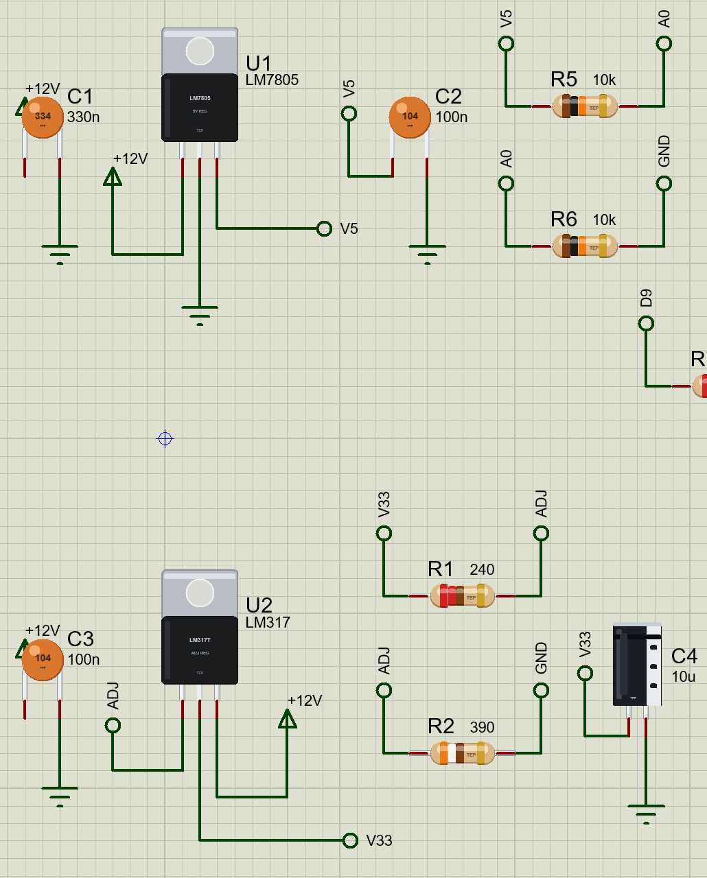
The devices are REG7805TEP and REGLM317TEP in TEPREG.LIB, under Power, Linear Regulators, with the prefix U and the model TEPREG.DLL. Search REG in Pick Devices. Each is drawn from the front at true scale, its legs pointing down. The LM7805's pins are IN, GND and OUT from left to right; the LM317's are ADJ, OUT and IN.
The Properties
| Property | What it does |
|---|---|
| Part (VALUE) | the label: LM7805 or LM317 |
| Heatsink | NONE (the bare tab, 54 °C/W to the air in all), SMALL (19 °C/W) or LARGE (9 °C/W) |
Download Voltage Regulator Library for Proteus
Click the button below to download Voltage-Regulator-Library-for-Proteus-v1.0.zip (about 2.9 MB, without the source code of the models):
Voltage Regulator Library for Proteus V1.0- README.txt: installation, the demo, the wiring of both regulators, the heat sums, troubleshooting and the limits.
- Proteus Library Files:
TEPREG.LIB, our resistor, power resistor, N-MOSFET and capacitor libraries, and ourArduinoV4TEP.LIB. - Proteus Model Files:
TEPREG.DLL, the DLLs of those parts andTEPARDUINO.DLL. - Arduino Code: the demo sketch.
- Proteus Simulation: the demo project, its HEX file and copies of the DLLs.
No Proteus yet? Read How to Download and Install Proteus 7 and 8. New to libraries? Follow How to Install a New Library in Proteus.
How to Install Voltage Regulator Library for Proteus
- Close Proteus and extract the whole zip file, for example to your Desktop.
- Copy the files from Proteus Library Files into the LIBRARY folder of Proteus.
- Copy the files from Proteus Model Files into the MODELS folder.
- Delete
TEPREG.IDXfrom the LIBRARY folder if it is there. - Start Proteus, press P and search for REG.
Demo: A Bare LM7805 Against an LM317 on a Heatsink
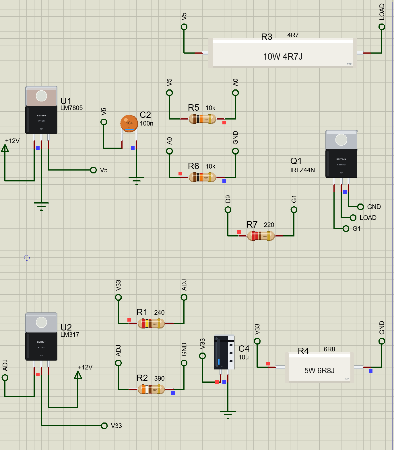
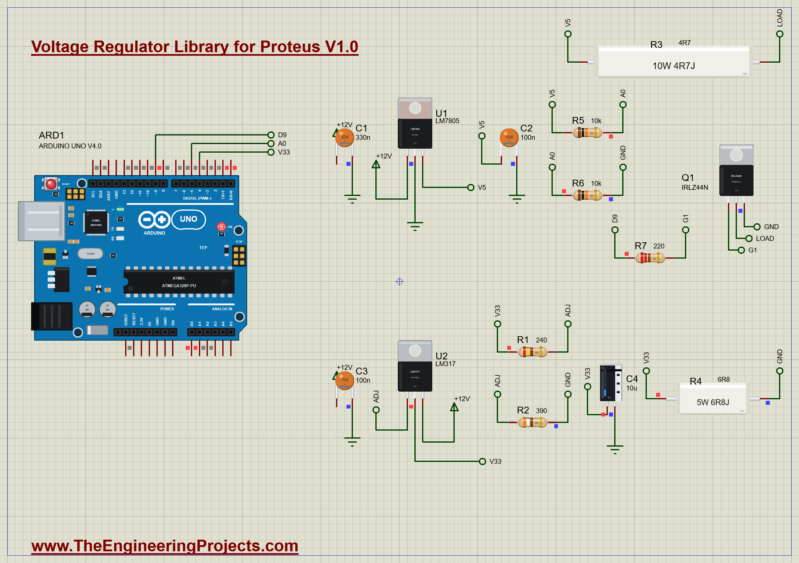
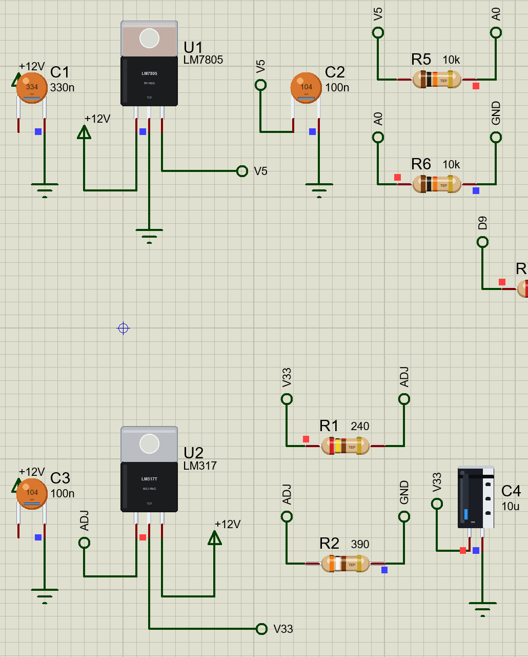
Both regulators run from a 12 V supply. U1 is an LM7805 with no heatsink, with C1 (330 nF) on its input and C2 (100 nF) on its output. Its load is R3, a 4.7 Ω, 10 W power resistor, switched by Q1, an IRLZ44N on D9 through R7 (220 Ω): about one amp. R5 and R6 (10k each) halve its output for the Arduino's A0. U2 is an LM317 on a large heatsink, set to 3.3 V by R1 (240 Ω) and R2 (390 Ω), with C3 (100 nF) on its input and C4 (10 µF) on its output. Its load is R4, 6.8 Ω, about half an amp, and A1 reads its output directly.
Open Voltage-Regulators-ArduinoUnoV4.pdsprj. It runs on our Arduino UNO Library for Proteus V4.0, with its built-in monitor, the same window as our TEP Serial Monitor Advance for Proteus. The load resistors come from our Power Resistor Library for Proteus, the switch from our N-MOSFET Library for Proteus, and the capacitors from our Ceramic Capacitor Library for Proteus and Electrolytic Capacitor Library for Proteus.
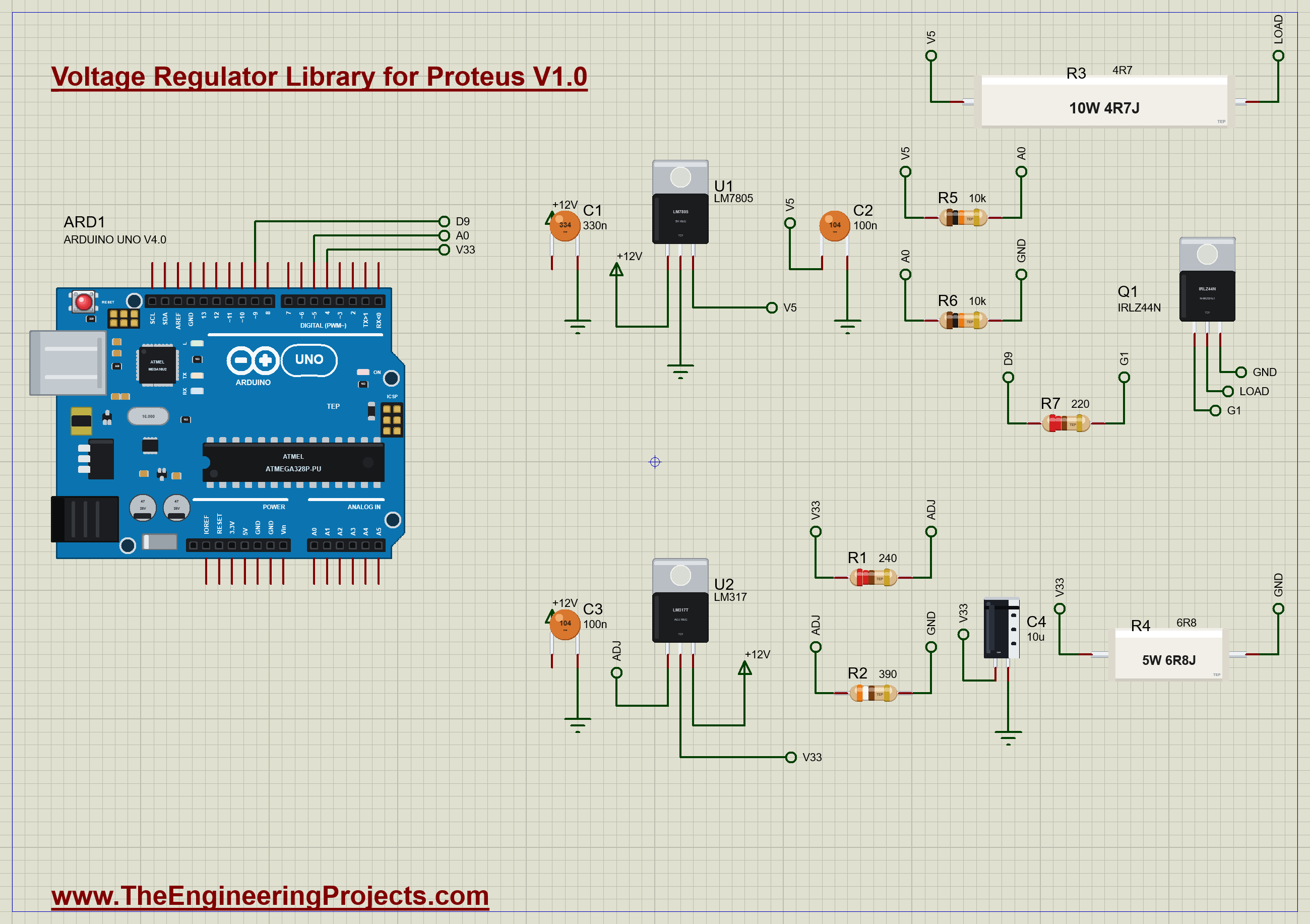
| Part | Connection | Job |
|---|---|---|
| U1 LM7805, C1, C2 | +12V - IN, OUT = V5, no heatsink | the 5 V supply |
| R3 4R7 10 W, Q1, R7 | V5 - R3 - Q1 - GND, gate from D9 | the 1 A load |
| R5, R6 10k | V5 - A0 - GND | half of V5 for the ADC |
| U2 LM317, R1 240, R2 390 | +12V - IN, OUT = V33, ADJ between R1 and R2 | the 3.3 V supply |
| C3, C4, R4 6R8 | on IN and OUT; R4 from V33 to GND | its capacitors and a 0.5 A load |
The Sketch
At two seconds the sketch switches the 7805's load on through Q1. A regulator in thermal shutdown switches on and off about once a second, so a reading taken once a second can land in the same part of every cycle and tell a misleading story. The sketch therefore checks the 7805's output every 10 ms and counts how often it is above 4.5 V:
  if (millis() - lastSample >= 10) {             // the 7805, every 10 ms
    lastSample = millis();
    const float v5 = 2 * volts(OUT_5V, 4);
    samples++;
    if (v5 > ON_LEVEL) { onSamples++; onSum += v5; }
  }
Once a second it prints the 7805's voltage while it was on, with the share of the second it was on when that is less than all of it, and the LM317's output:
    if (onSamples == 0) Serial.print(F("off (too hot)"));
    else {
      Serial.print(onSum / onSamples, 2);
      Serial.print(F(" V"));
      if (onSamples < samples) {
        Serial.print(F(", on "));
        Serial.print(100L * onSamples / samples);
        Serial.print(F(" % (too hot)"));
      }
    }
Run the Demo
Before the Load
Press Run. For the first two seconds the 7805 feeds only its divider and its own internal circuit: 5.008 V, a quarter of a milliamp out, and hardly any heat. Its pop-up shows the input as a column: the green part is the output, the orange part the voltage the regulator drops, and the white line the least input it needs.
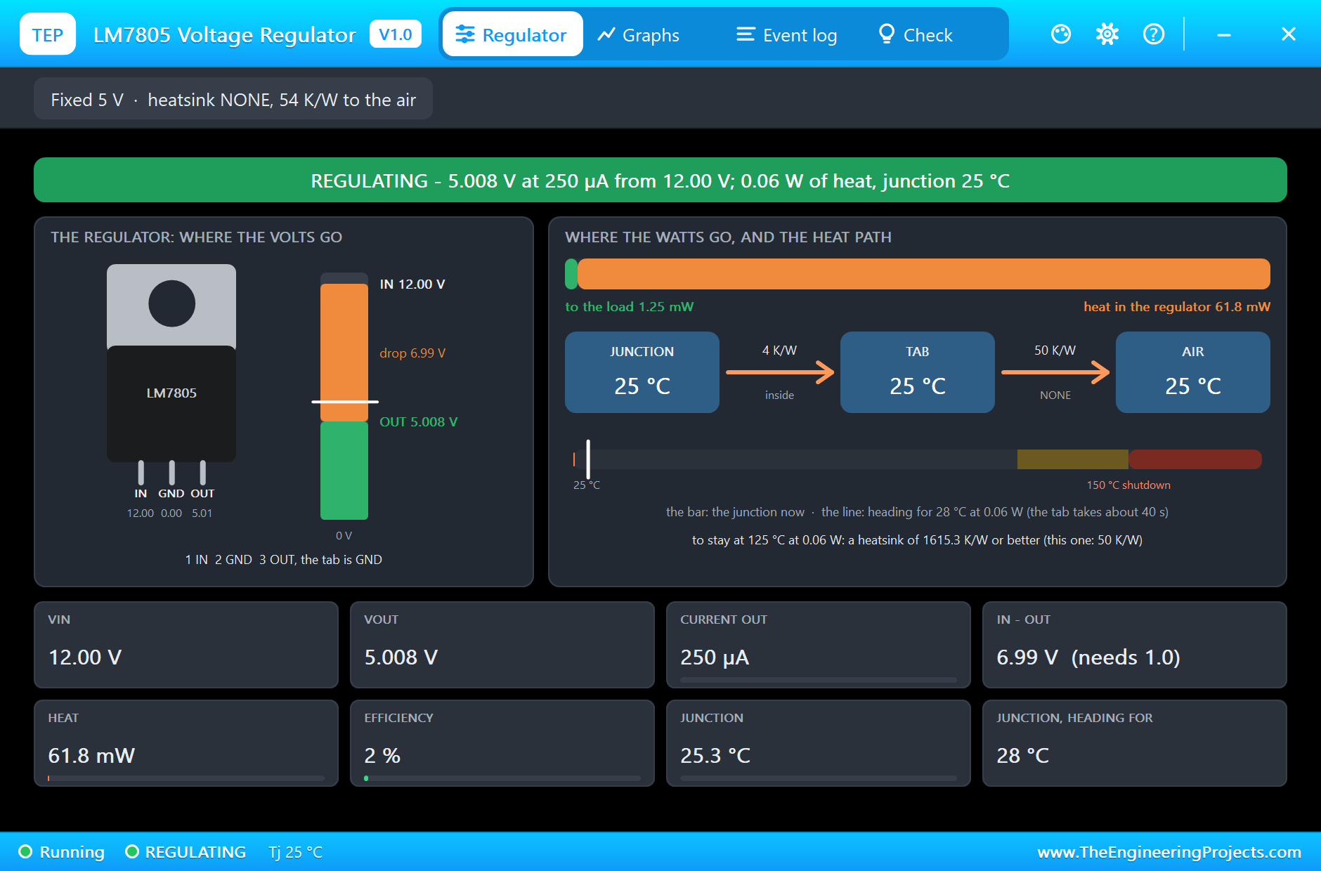
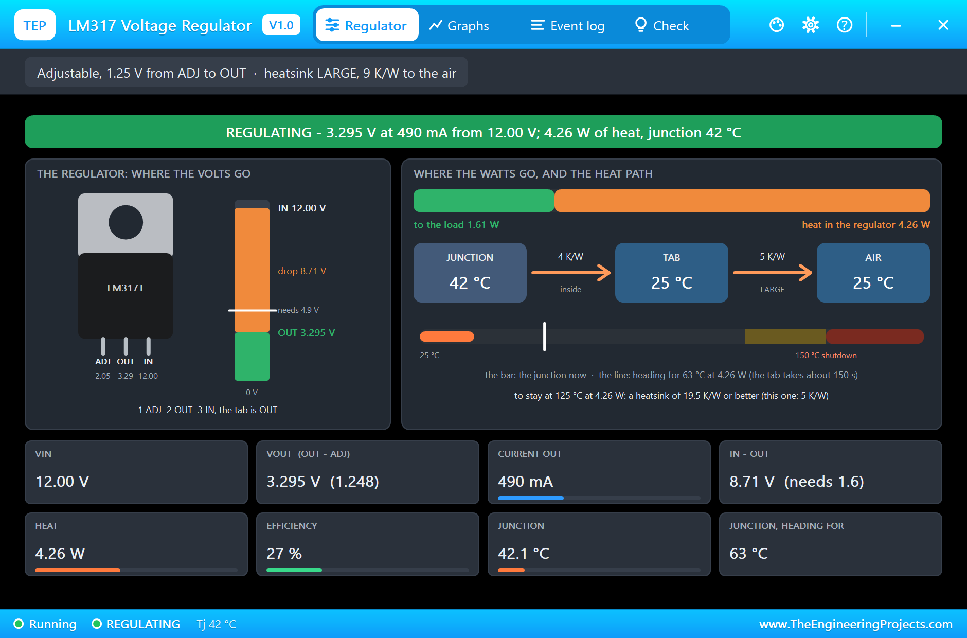
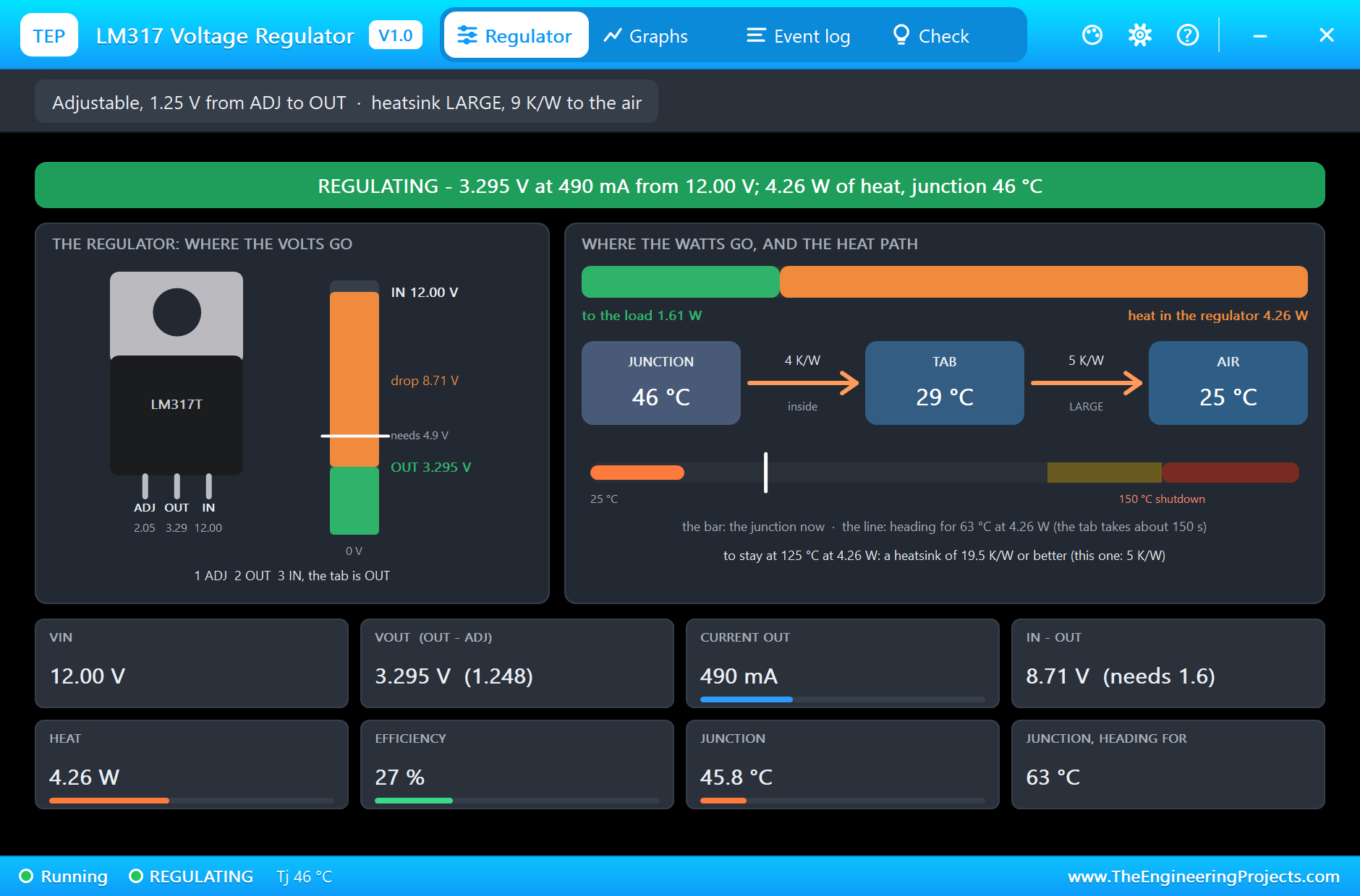
The LM317 starts with its load at once: 3.295 V out at 490 mA, with exactly 1.248 V between OUT and ADJ. It drops 8.7 V at half an amp, so it burns 4.26 W and passes only 27 % of its input power to the load. On its large heatsink, though, its junction is heading for only 63 °C:
Here is the complete circuit running:
One Amp From a Bare TO-220
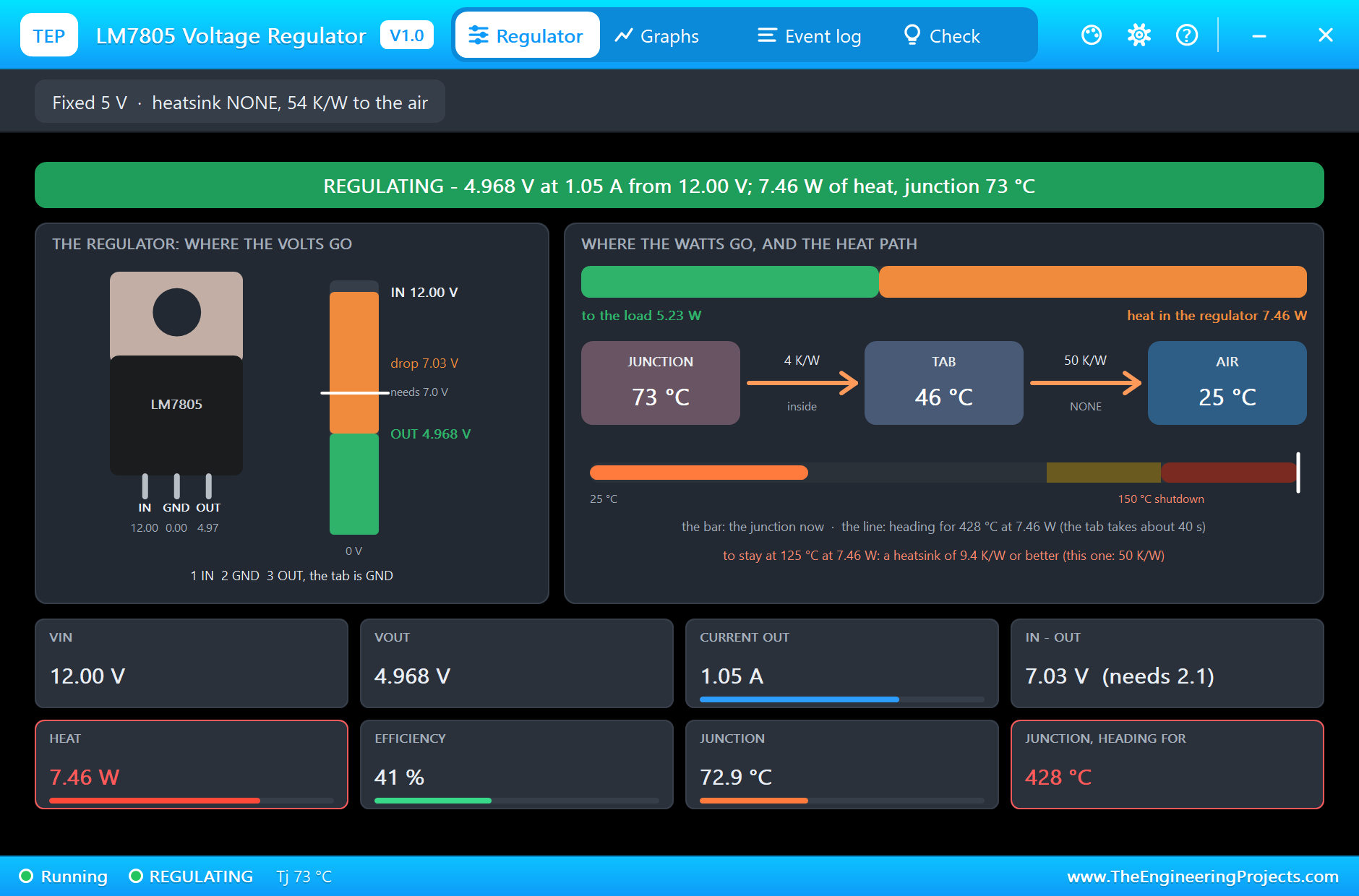
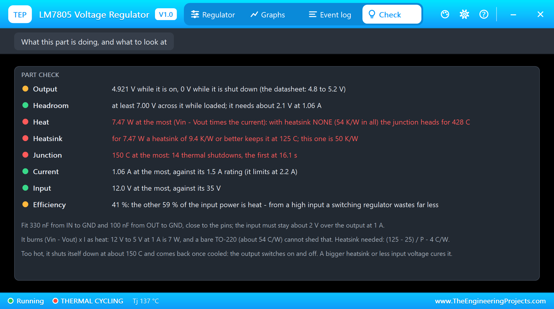
At two seconds Q1 switches the load on, and the 7805 delivers 1.05 A. It drops 7 V at that current, which is 7.46 W of heat. Three seconds later its junction is already at 73 °C and its tab at 46 °C, and the white line on the temperature bar has jumped off the scale: with no heatsink, this power would carry the junction to about 428 °C. The pop-up's advice line says what it would take to stay at 125 °C: a heatsink of 9.4 °C/W or better. Notice also that the output has slipped a little, to 4.968 V: the 7805's output falls about 0.6 mV for every degree its junction warms.
Thermal Shutdown
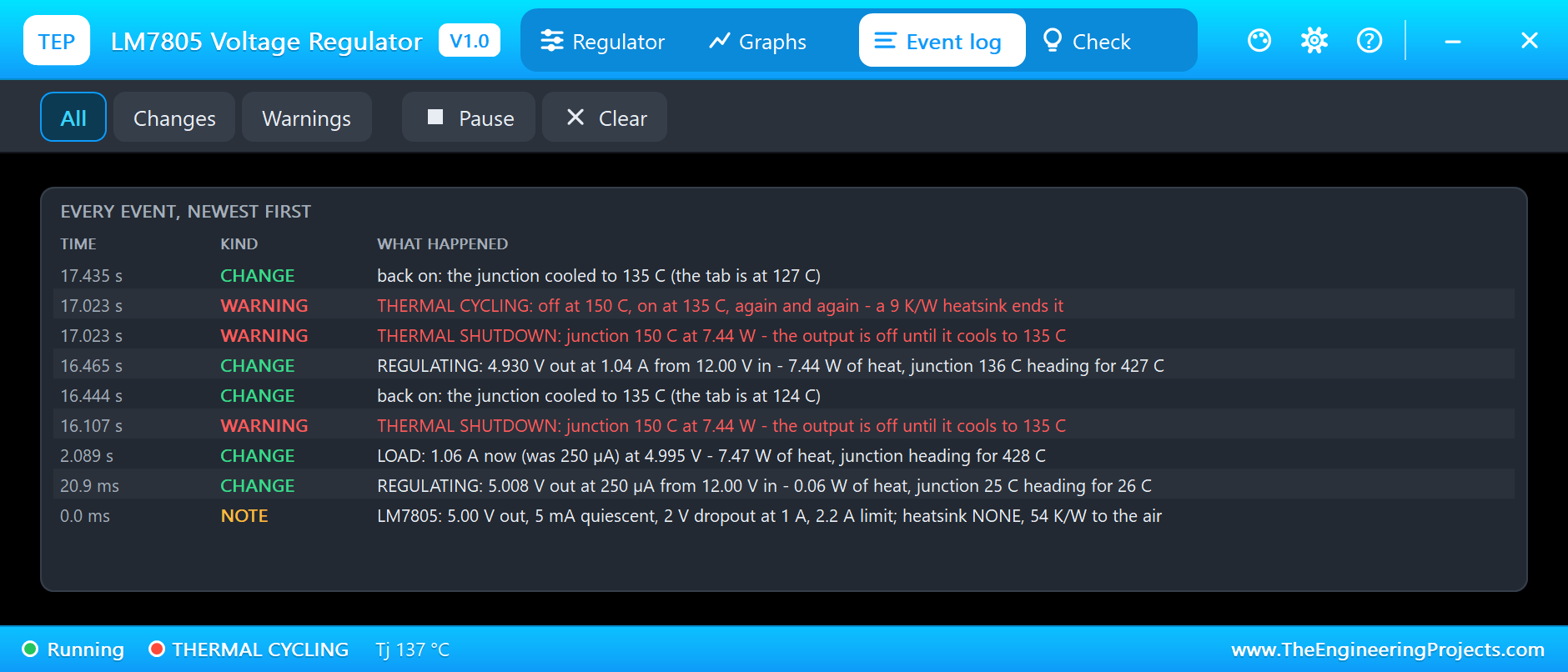
The tab heats more slowly than the junction, but it never stops. At 16.1 s the junction reaches 150 °C and the thermal shutdown switches the output off. The banner turns red, the output column empties, and the heat falls to the regulator's own few milliwatts. The junction cools quickly towards the hot tab:
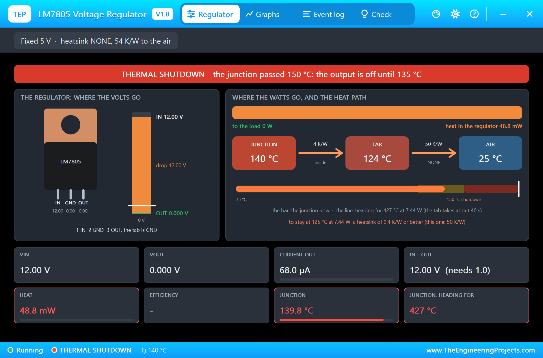
Thermal Cycling
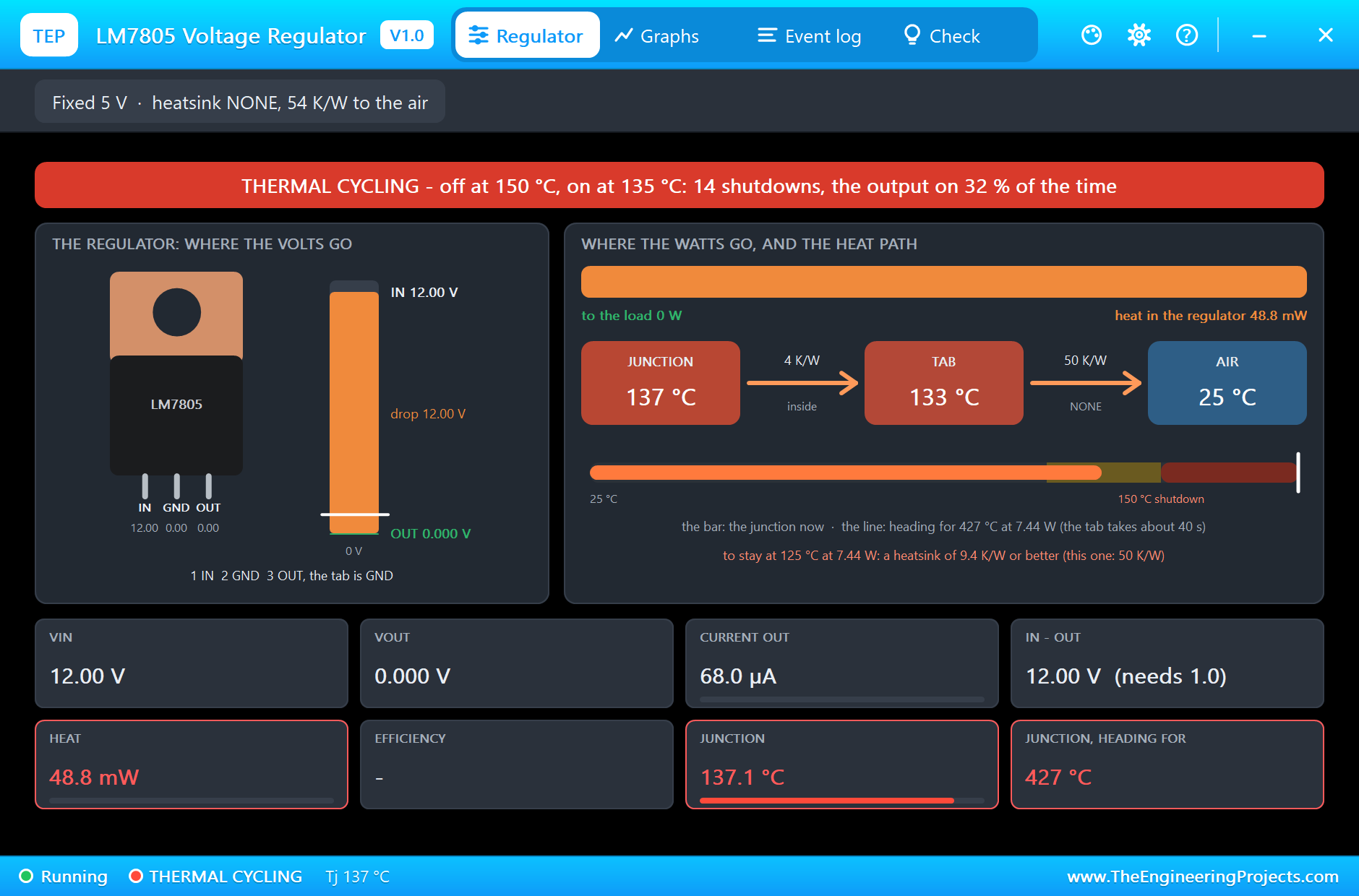
A third of a second later the junction has cooled to 135 °C and the output comes back, but the tab is still at 124 °C, so the junction is back at 150 °C about 0.6 s later. From then on the 7805 cycles: on for about 0.4 s, off for nearly a second. By thirty seconds it has shut down 14 times and its output is on only about 32 % of the time:
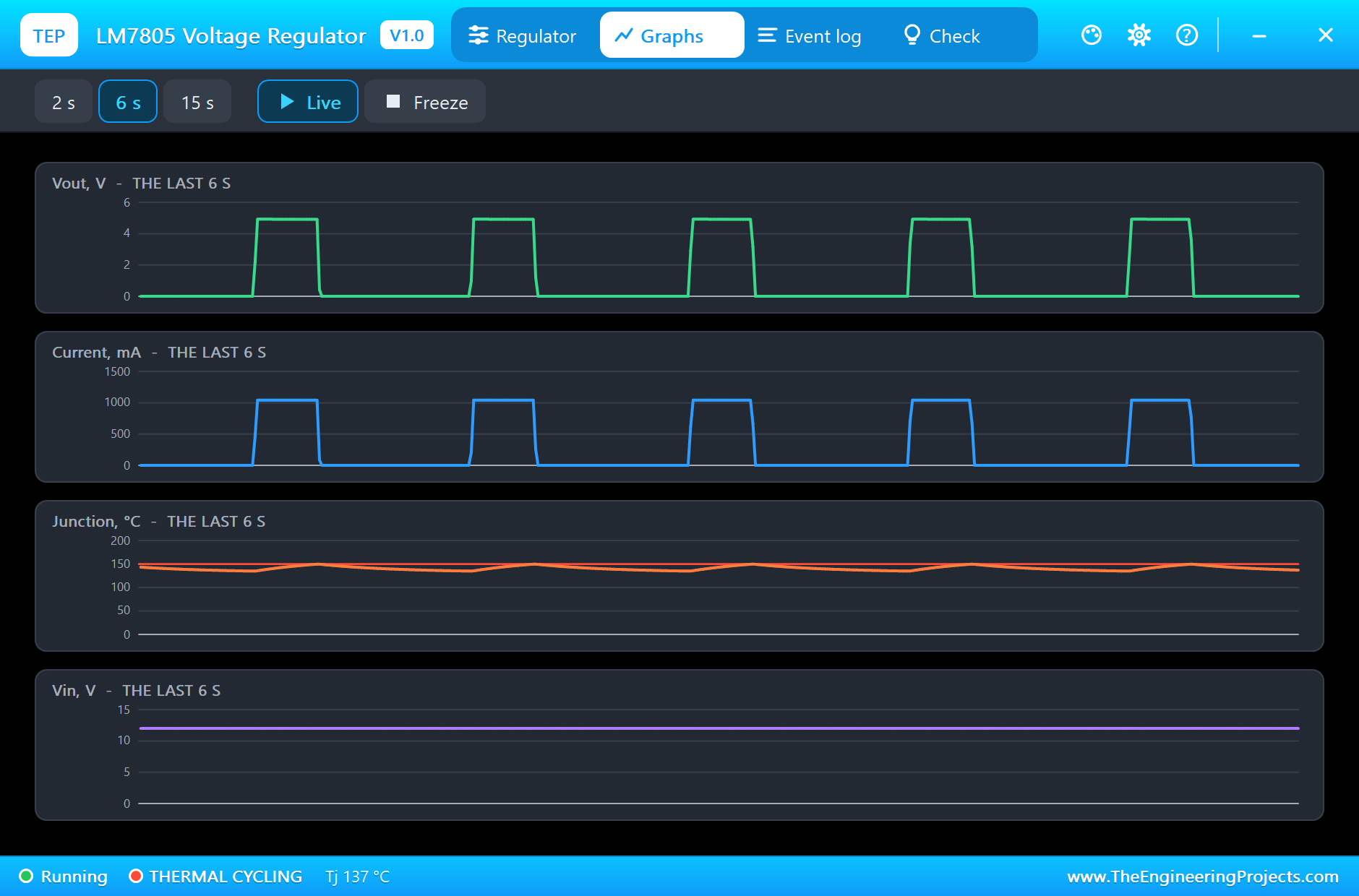
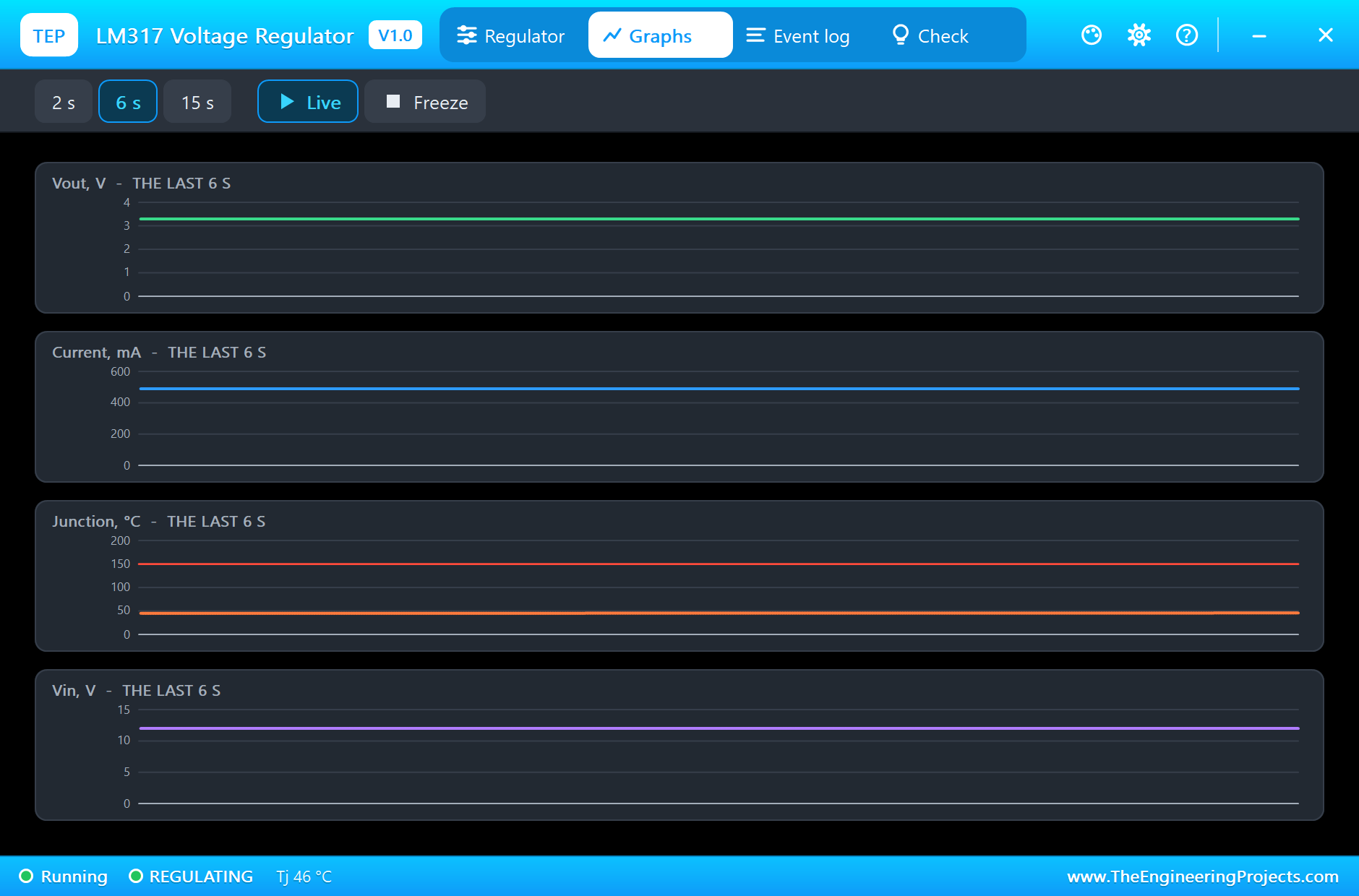
The Graphs page shows the cycle plainly: the output and the current switching on and off together, and the junction sawing between 135 °C and 150 °C:
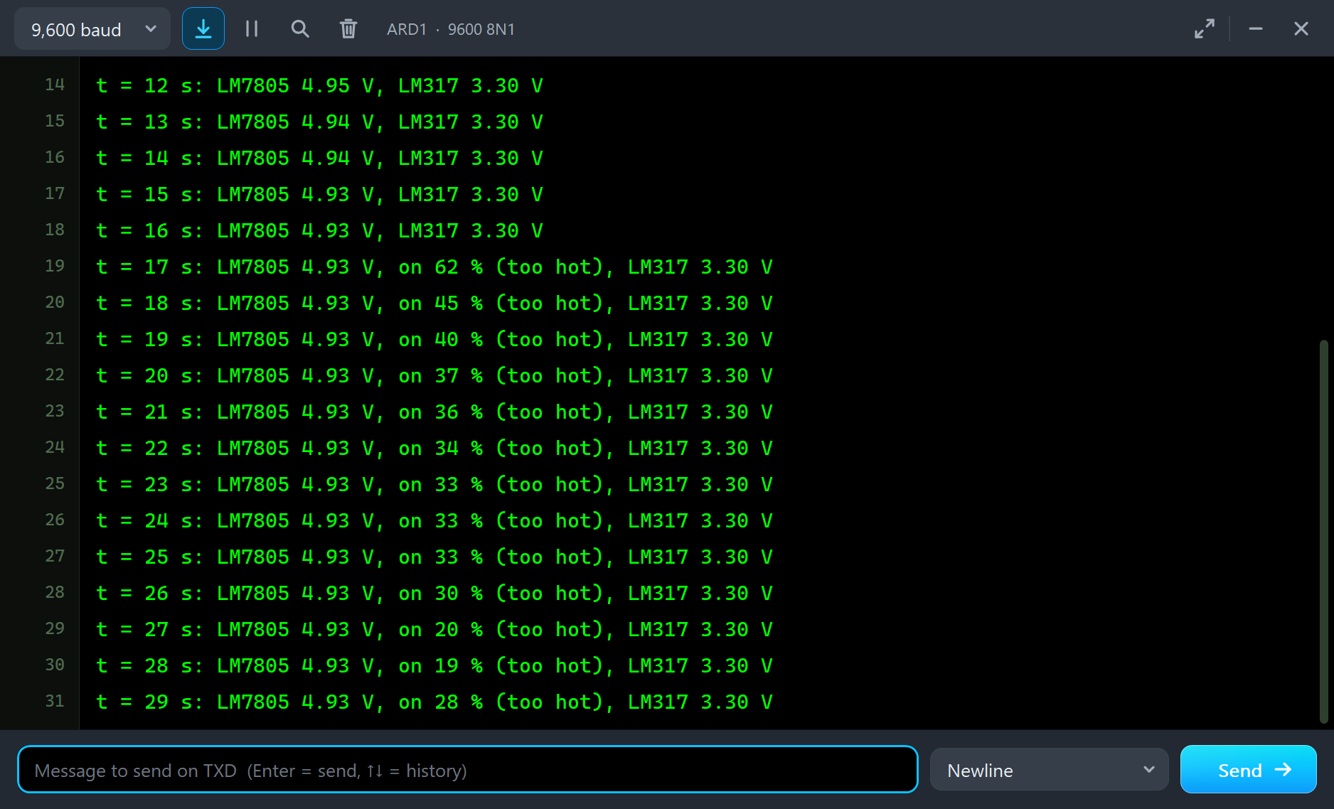
The Arduino sees it too. With the load on, the monitor reads 4.94 V and then 4.93 V as the junction warms. From 17 s it adds how much of each second the output was on: 62 %, then 45 %, 40 %, and down to about a third, while the LM317 reads 3.30 V every time:
The LM317 on Its Heatsink
All this time the LM317 has held its 3.295 V. Its junction has climbed slowly to 46 °C and its large heatsink to 29 °C, still on their way to 63 °C. It burns more than half as much heat as the 7805, but its heatsink sheds it six times better than a bare tab:
The Log and the Check Pages
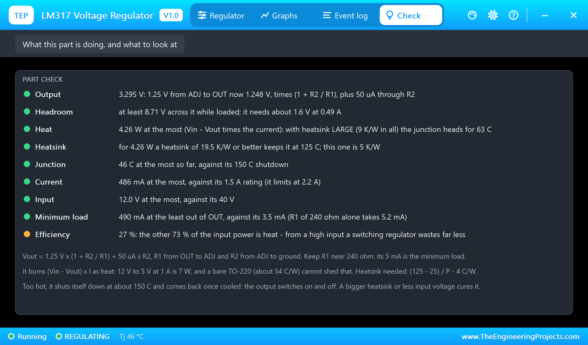
The 7805's Event log tells the story in order: regulating without a load, the load arriving with the forecast already far beyond the limit, the first shutdown, the restart, and the cycling. Its Check page gives the verdict: 7.47 W of heat, a junction heading for over 400 °C, 14 shutdowns, and a heatsink of 9.4 °C/W or better needed. The LM317's Check page is all green: a 3.3 V output with its sums, plenty of headroom, a cool junction, its minimum load met and a heatsink with room to spare:
Try It Yourself
- Set U1's heatsink to LARGE and run again: the shutdowns disappear and the forecast falls to about 90 °C.
- Change R3 to 47 Ω: a tenth of the current, and the bare 7805 heads for only about 65 °C.
- Lower the supply to 8 V: less than half the heat, still too much for a bare tab, and the headroom nears the 2 V dropout.
- Change R2 to 720 Ω for a 5 V LM317, or 1k5 for about 9 V.
- Change R1 and R2 to 2k4 and 3k9 and remove R4: below its minimum load, the LM317's output creeps up.
Ideas to Extend the Demo
- Switch the 7805's load with PWM and see how the average power sets the temperature.
- Build a variable bench supply with the LM317 and a potentiometer for R2.
- Add an NTC thermistor on the tab and let the Arduino cut the load before the shutdown does.
- Compare a 7805 from 7 V, 9 V and 12 V at the same load, and plot the heat.
Your Own Sketches
The demo sketch is in the zip file, and you can change it in the Arduino IDE. New to Arduino? Start with our Arduino Tutorial for Beginners. Export the compiled binary, and set the UNO's PROGRAM property to the new file. Our guide on How to get the HEX file from Arduino shows you where the file ends up.
Things to Know Before Using a Real Regulator
- Work out the heat first: (Vin - Vout) x I; a bare TO-220 handles only about 1 W to 1.5 W.
- Size the heatsink: (125 - 25) / P - 4 °C/W, and use thermal paste or a pad; on the LM317 the tab is OUT, so insulate it from a grounded heatsink.
- Mind the dropout: keep the input about 2 V above the output at full current.
- Fit the capacitors close: without them a regulator can oscillate.
- Consider a switching regulator for big currents from a high input.
Troubleshooting
- THERMAL CYCLING or SHUTDOWN: too much heat; add a heatsink, lower the input or the current.
- DROPOUT: the input is too close to the output; raise it.
- CURRENT LIMIT: the load takes more than 2.2 A, or the output is shorted.
- BELOW MINIMUM LOAD: the LM317 has less than 3.5 mA to feed; keep R1 at 240 Ω.
- The part is not simulated:
TEPREG.DLLis missing from MODELS and from the project folder.
Limitations of the Simulation
- The regulation is static: the loop's speed, its ripple rejection against frequency and its noise are not modelled.
- Reverse current from OUT to IN, when the input is removed with a charged output capacitor, is not modelled.
- The heatsink values are typical, and the restart temperature of 135 °C is our model's choice; the datasheets give only the shutdown.
- Arduino is a name of Arduino; this library is not made or endorsed by Arduino or Labcenter.
- Tested in Proteus 8.5 in November 2026 (the demo as shipped). Proteus 7 is not supported.
So, that was all about the Voltage Regulator Library for Proteus. I hope it helps you build steady supplies and, above all, work out the heat before the smoke does it for you. If you have any questions, ask in the comments and I will help you out. Till the next tutorial, take care and have fun!