


Project Files of Voltage Regulator Library for Proteus: LM7805, LM317
 Libraries
 Code
 Projects
 Simulation
voltage-regulator-tep-v1-0-addce0d7e8194a71bea3557634f4d09b.zip

Voltage Regulator Library for Proteus V1.0
Voltage Regulator Library for Proteus V1.0 comes as a ZIP archive of 25 files (2.8 MB, 6.1 MB unpacked) holding Proteus library files, simulation model DLLs, a Proteus simulation, an Arduino sketch and compiled HEX firmware.
- LIBProteus library
- DLLProteus model
- DSNProteus simulation
- INOArduino sketch
- HEXHEX firmware
Description
Voltage-Regulator-Library-for-Proteus-v1.0.zip with real-looking LM7805 and LM317 voltage regulators for Proteus (regulation, dropout, current limit, heat, heatsink and thermal shutdown; a pop-up with where the volts and watts go; TEPREG.LIB and TEPREG.DLL), our power resistors, IRLZ44N, capacitors, resistors, Arduino UNO V4.0, the A4 demo with its sketch and a README.

File Structure
 File Structure
2.7 KB201.9 KB36 KB10.1 KB17.9 KB157.2 KB15.2 KB306.9 KB883.5 KB300.5 KB294.5 KB295 KB304.5 KB306 KB311 KB15.6 KB883.5 KB300.5 KB294.5 KB295 KB304.5 KB306 KB311 KB30.1 KB14.6 KBGallery12 images from the tutorialOpen the tutorial
 Gallery12 images from the tutorial
The circuit, the board and the results as they appear in Voltage Regulator Library for Proteus: LM7805, LM317. Open an image for its full size.
README
 README
VOLTAGE REGULATOR LIBRARY FOR PROTEUS - V1.0 (the LM7805 and the LM317 with their heat, and a pop-up)
Designed by The Engineering Projects
www.TheEngineeringProjects.com

IMPORTANT LINKS
Article (read it first - pictures, step by step, every feature explained):
  https://www.theengineeringprojects.com/2026/11/voltage-regulator-library-for-proteus.html
Report a bug or suggest a feature (our forum):
  https://www.theengineeringprojects.com/forum/category/voltage-regulator-proteus-library
The demo runs on our Arduino UNO V4.0 (included) - working LEDs, RESET and a
built-in serial monitor, no Virtual Terminal to wire - its own article:
  https://www.theengineeringprojects.com/2026/10/arduino-uno-library-for-proteus-v40.html
Its load resistors are our own power resistors (included):
  https://www.theengineeringprojects.com/2026/11/power-resistor-library-for-proteus.html
the switch our own IRLZ44N MOSFET (included):
  https://www.theengineeringprojects.com/2026/11/n-mosfet-library-for-proteus.html
and the capacitors our own ceramic and electrolytic parts (included):
  https://www.theengineeringprojects.com/2026/11/ceramic-capacitor-library-for-proteus.html
Support us (the libraries are free):
  https://www.theengineeringprojects.com/donate

FILE STRUCTURE
Voltage-Regulator-TEP-v1.0/
|-- Proteus Library Files/
|   |-- ArduinoV4TEP.LIB                              201.9 KB   TEP Arduino boards V4.0 (UNO) -> LIBRARY
|   |-- TEPCERAMIC.LIB                                 36.0 KB   a part the demo uses -> LIBRARY folder
|   |-- TEPELECTRO.LIB                                 10.1 KB   a part the demo uses -> LIBRARY folder
|   |-- TEPNMOS.LIB                                    17.9 KB   a part the demo uses -> LIBRARY folder
|   |-- TEPPOWERRES.LIB                               157.2 KB   a part the demo uses -> LIBRARY folder
|   |-- TEPREG.LIB                                     15.2 KB   the library -> LIBRARY folder
|   |-- TEPRESISTOR.LIB                               306.9 KB   a part the demo uses -> LIBRARY folder
|-- Proteus Model Files/
|   |-- TEPARDUINO.DLL                                883.5 KB   the Arduino board model -> MODELS folder
|   |-- TEPCERAMIC.DLL                                300.5 KB   its model -> MODELS folder
|   |-- TEPELECTRO.DLL                                294.5 KB   its model -> MODELS folder
|   |-- TEPNMOS.DLL                                   295.0 KB   its model -> MODELS folder
|   |-- TEPPOWERRES.DLL                               304.5 KB   its model -> MODELS folder
|   |-- TEPREG.DLL                                    306.0 KB   the model -> MODELS folder
|   |-- TEPRESISTOR.DLL                               311.0 KB   its model -> MODELS folder
|-- Proteus Simulation/
|   |-- Regulator_Demo.hex                             15.6 KB   the demo firmware
|   |-- TEPARDUINO.DLL                                883.5 KB   copy of the board model
|   |-- TEPCERAMIC.DLL                                300.5 KB   copy of its model
|   |-- TEPELECTRO.DLL                                294.5 KB   copy of its model
|   |-- TEPNMOS.DLL                                   295.0 KB   copy of its model
|   |-- TEPPOWERRES.DLL                               304.5 KB   copy of its model
|   |-- TEPREG.DLL                                    306.0 KB   copy of the model
|   |-- TEPRESISTOR.DLL                               311.0 KB   copy of its model
|   |-- Voltage-Regulators-ArduinoUnoV4.pdsprj         30.1 KB   the demo project
|-- Arduino Code/
|   |-- Regulator_Demo/Regulator_Demo.ino               2.7 KB   the demo sketch (source of the .hex)
|-- README.txt                                        ~14.6 KB   this file
Total: 6.05 MB (unzipped). The C++ source code of the models is not included.

WHAT IS IT?
Two linear voltage regulators in the TO-220 package, drawn at true scale (the black body, the metal
tab with its hole, three legs 2.54 mm apart):
  * LM7805 - a fixed 5 V regulator. Pins 1 IN, 2 GND, 3 OUT; the tab is GND.
  * LM317 - an adjustable regulator: it holds 1.25 V from ADJ to OUT, and two resistors set the
    output. Pins 1 ADJ, 2 OUT, 3 IN; the tab is OUT.
  * One analog model with the datasheet values (TI LM7805 and LM317): the set voltage with its line
    and load regulation, the dropout (about 2 V at
    1 A), the 2.2 A current limit (the LM317's folding back at high input), the quiescent current,
    the LM317's 50 uA from ADJ and its minimum load,
    and the heat: the power it burns flows from the junction through the tab and the heatsink (a
    property: NONE, SMALL or LARGE) to the air.
  * Past 150 C at the junction the thermal shutdown turns the output off; it comes back once the
    junction has cooled to 135 C. The tab warms in
    colour on the sheet.
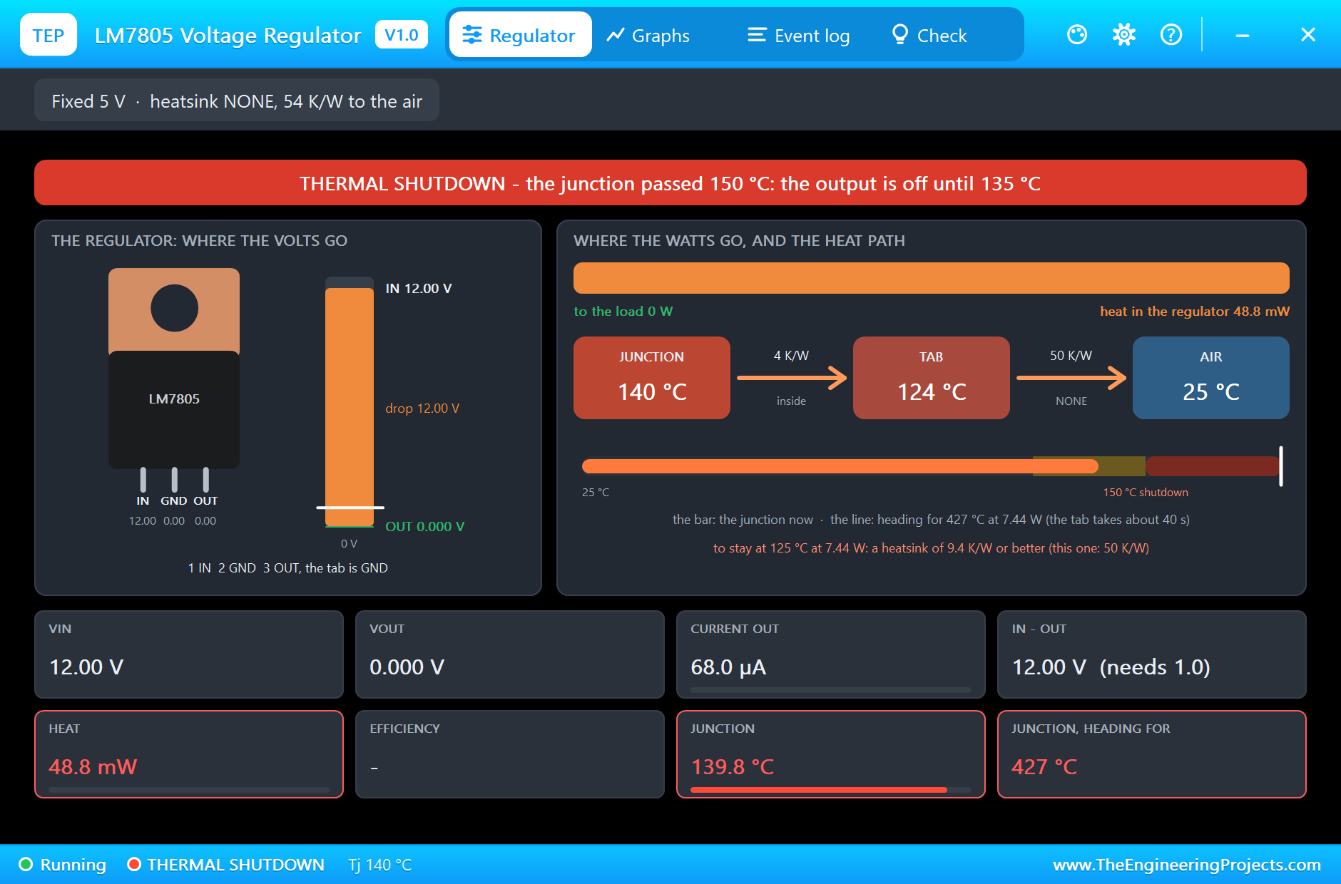
  * Click one at Run for the pop-up: where the input volts go (the output and the drop), where the
    watts go (the load and the heat), the heat path
    with each temperature and where the junction is heading, graphs, an event log and a check page
    that sizes a heatsink.
The body is drawn as on the real part and to true scale against our Arduino.
The TEP signature and the pop-up are TEP additions.

TWO DEVICES (search "REG" in Pick Devices):
  REG7805TEP    "LM7805 Regulator V1.0" in TEPREG.LIB (Power > Linear Regulators), prefix U, model
  TEPREG.DLL. Pins IN, GND, OUT.
  REGLM317TEP   "LM317 Regulator V1.0" in TEPREG.LIB, prefix U, model TEPREG.DLL. Pins ADJ, OUT, IN.

THE POP-UP
Click the part at Run. Tabs:
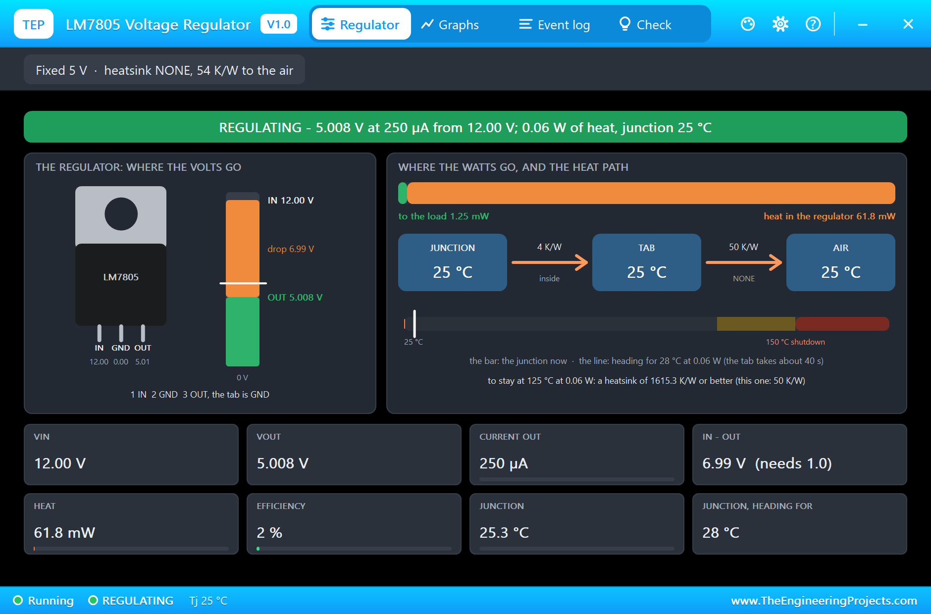
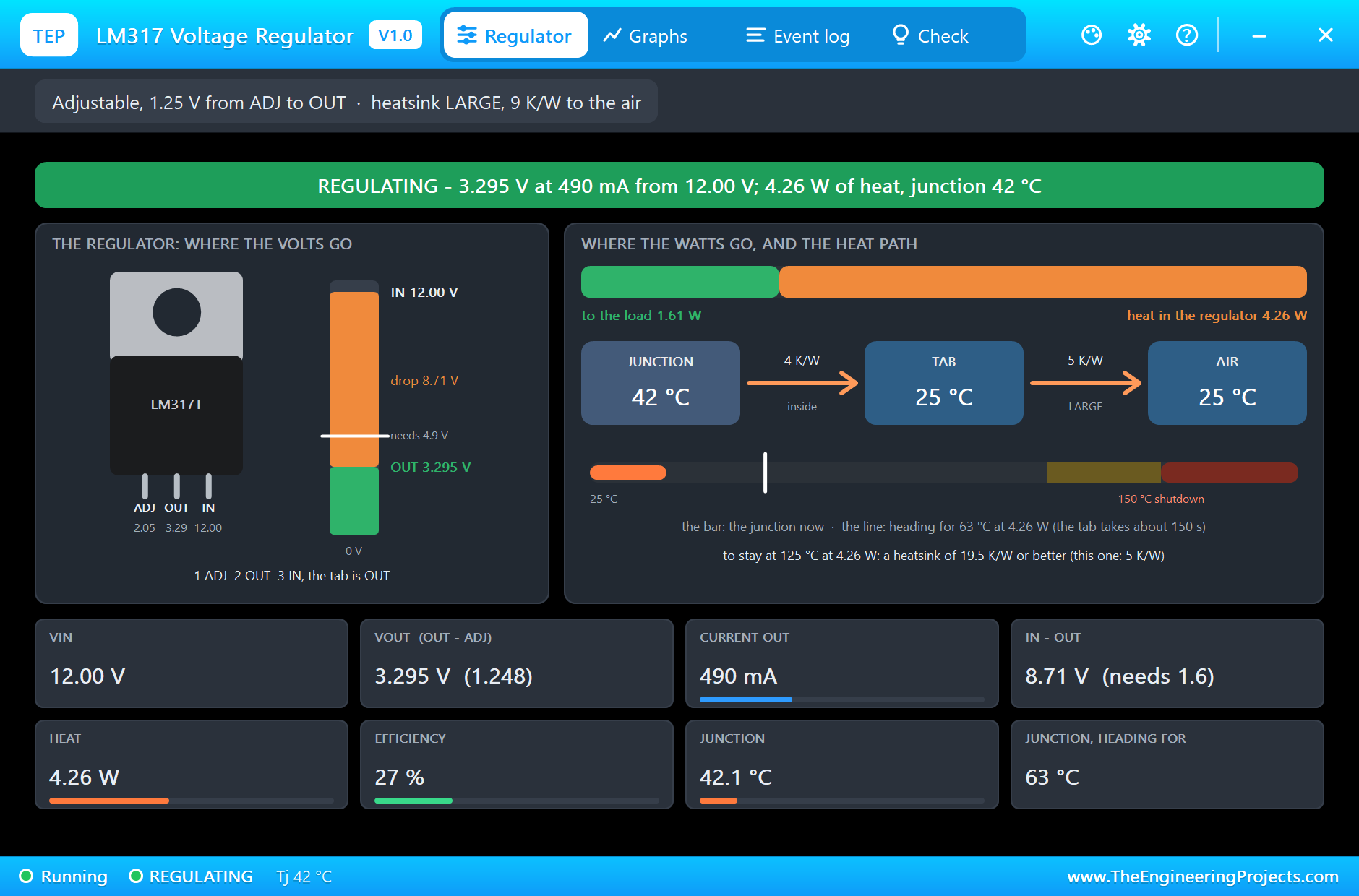
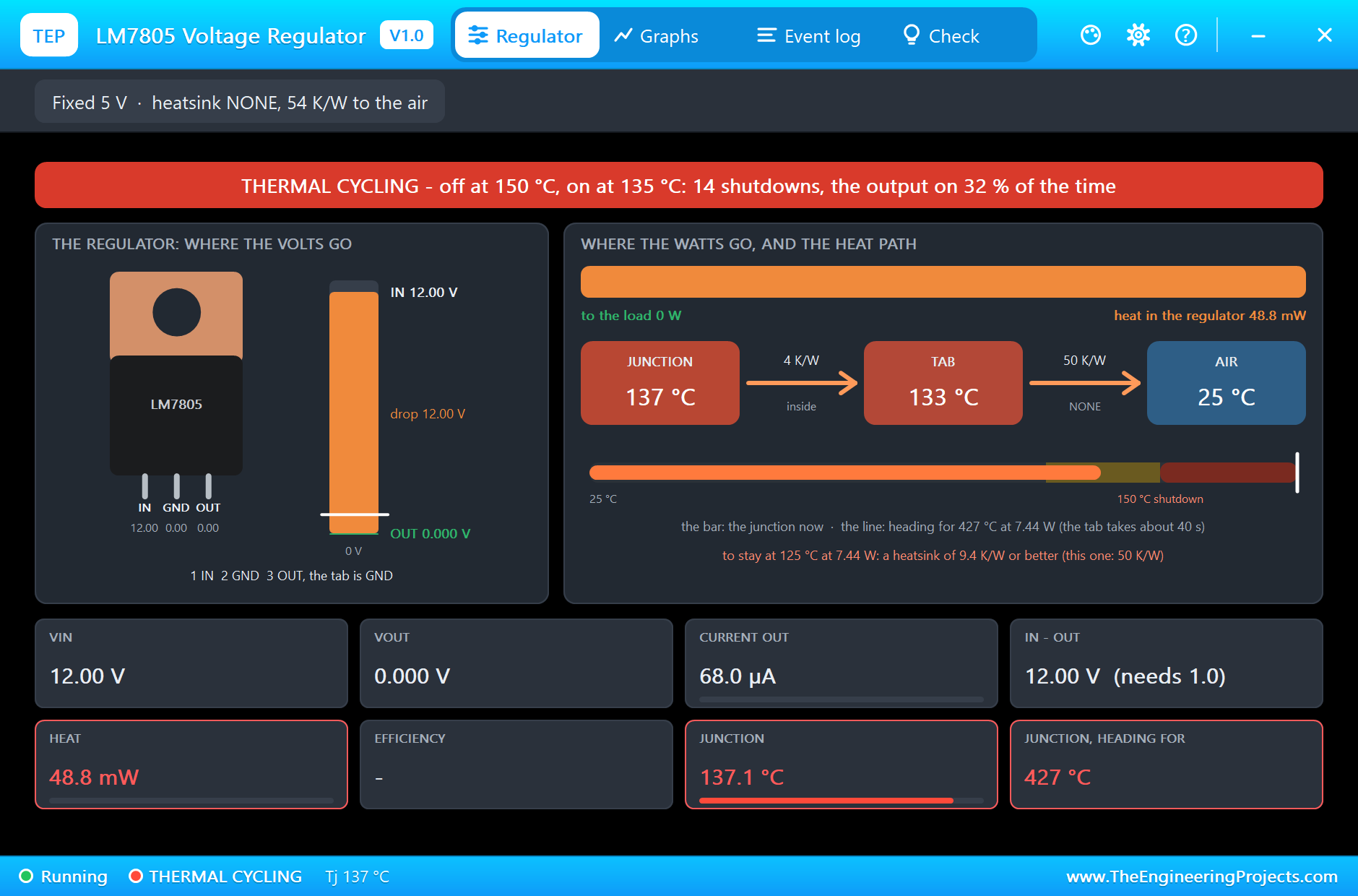
    Regulator  the part with its tab warming, the input as a column split into the output and the
    drop (with the least input it needs), the input
               power split into the load's and the heat, the heat path (junction - tab - air) with a
               bar of the junction against the 150 C
               shutdown and where it is heading, and eight live values: Vin, Vout, the current, IN -
               OUT, the heat, the efficiency, the junction
               and the forecast. The toolbar: the part and its heatsink.
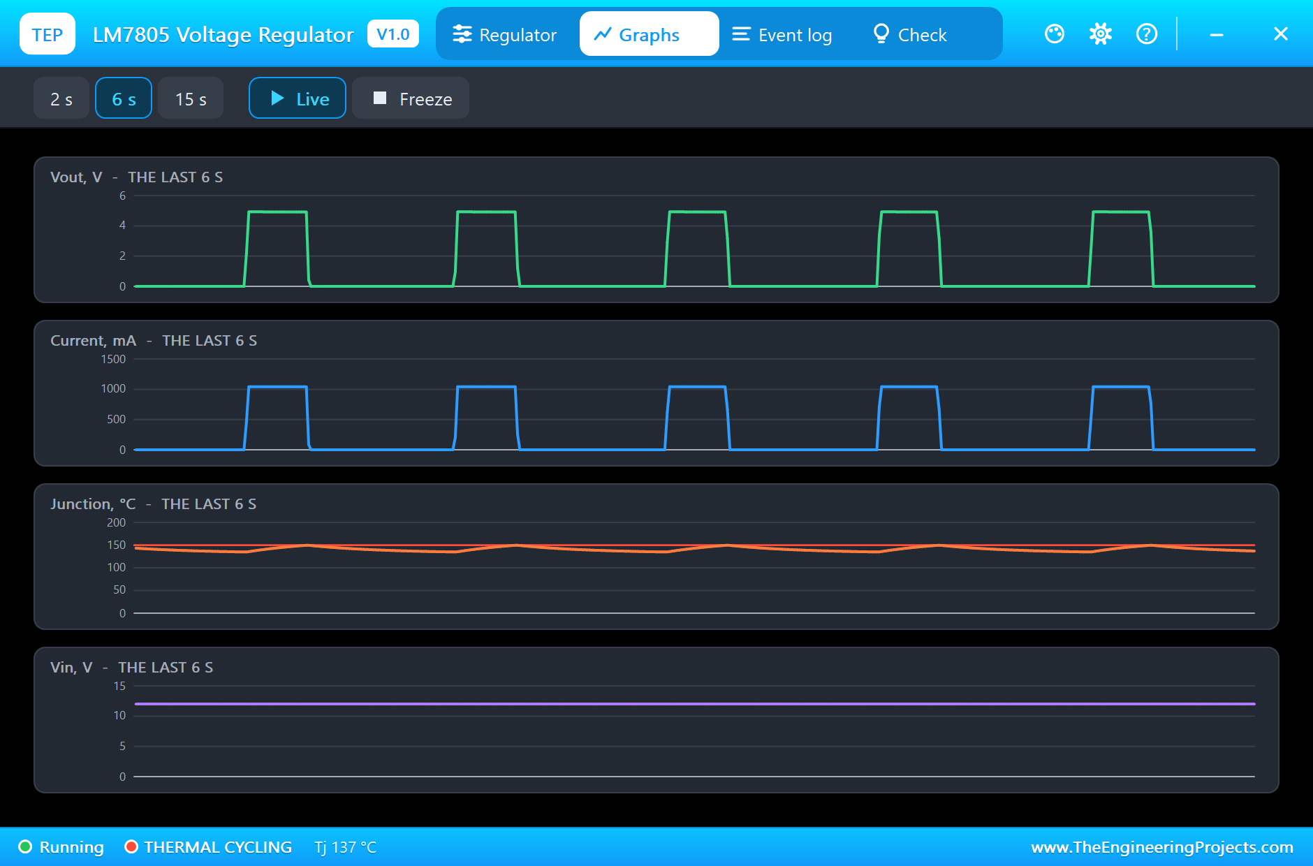
    Graphs     the live values over the last 2, 6 or 15 s. Live / Freeze.
    Event log  every change and warning; filters All / Changes / Warnings, Pause, Clear
    Check      what the part is doing and what to look at, each with a verdict (green = fine, amber
    = check, red = wrong)
    Settings   theme, text size, open at Run, window size
    Help       report a bug, suggest a feature, article, updates, donate, forum; Copy diagnostics
    for a bug report

TEST STATUS
V1.0: verified in Proteus 8.5 on 31 Oct 2026 (the demo project as shipped: an A4 sheet, an Arduino UNO V4.0).
What the runs showed (the model's own numbers and the sketch's monitor):
  * The project loads and starts cleanly; the sketch prints both outputs every second and switches
    the LM7805's 1 A load on at 2 s.
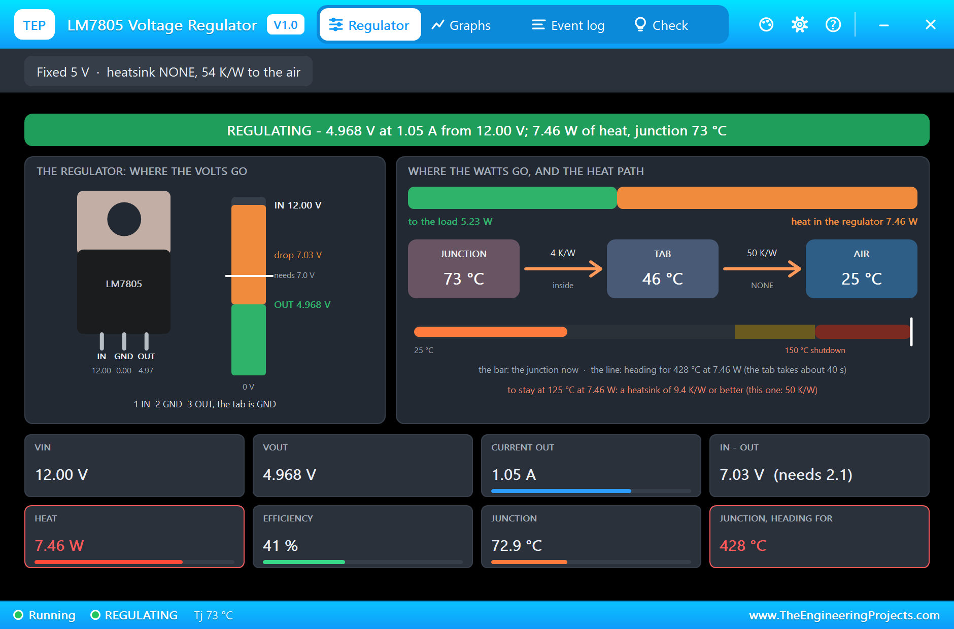
  * U1 (LM7805, no heatsink, 12 V in): 5.008 V before the load (250 uA out). With the 4.7 ohm load:
    1.06 A at 4.995 V, 7.47 W of heat, the
    junction heading for 428 C; at 5 s 4.968 V (the output falls 0.6 mV per degree), junction 73 C,
    tab 46 C - the pop-up asks for a heatsink of
    9.4 K/W or better. First THERMAL SHUTDOWN at 16.1 s (junction 150 C), back on at 16.4 s (cooled
    to 135 C, the tab at 124 C), THERMAL CYCLING
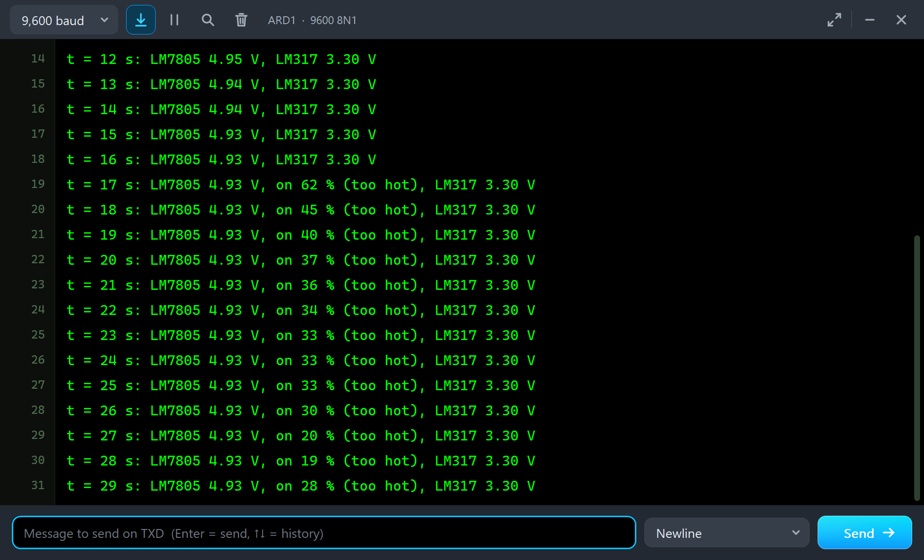
    from 17.0 s: 14 shutdowns by 30 s, the output on 32 % of the time. The monitor: 4.94 then 4.93 V
    while it held, then "on 62 %", 45 %, 40 %
    ... about a third of each second (too hot).
  * U2 (LM317 on a LARGE heatsink, R1 240, R2 390): 3.295 V (1.248 V from ADJ to OUT) at 490 mA from
    12 V, 4.26 W of heat, 27 % efficient;
    junction 42 C at 2 s and 46 C at 30 s (tab 29 C), heading for 63 C; minimum load met. The
    monitor read 3.30 V every second.
  * The pop-up: Regulator (where the volts and the watts go, the heat path with the forecast),
    Graphs, Event log, Check - all four pages
    followed the run, for both regulators.

INSTALLATION (about 2 minutes)
1. Close Proteus. Extract the WHOLE ZIP to a normal folder (e.g. Desktop).
2. Copy everything in "Proteus Library Files" (TEPREG.LIB, TEPRESISTOR.LIB, TEPPOWERRES.LIB,
TEPNMOS.LIB, TEPCERAMIC.LIB, TEPELECTRO.LIB and our Arduino library V4.0, ArduinoV4TEP.LIB, with the
ARDUINO UNO V4.0 used by the demo) to the LIBRARY folder of Proteus, for example:
     C:\Program Files (x86)\Labcenter Electronics\Proteus 8 Professional\LIBRARY
   (use the folder that already holds Proteus's own .LIB files).
3. Copy TEPREG.DLL, TEPRESISTOR.DLL, TEPPOWERRES.DLL, TEPNMOS.DLL, TEPCERAMIC.DLL, TEPELECTRO.DLL
and TEPARDUINO.DLL from "Proteus Model Files" to the MODELS folder (...\Proteus 8
Professional\MODELS).
4. Delete TEPREG.IDX from the LIBRARY folder if it is there (Proteus makes a new index).
5. Start Proteus. In Pick Devices (P) search "REG".

RUN THE DEMO
"Proteus Simulation\Voltage-Regulators-ArduinoUnoV4.pdsprj" (an A4 sheet) - keep the .hex file and
the DLLs beside the project.
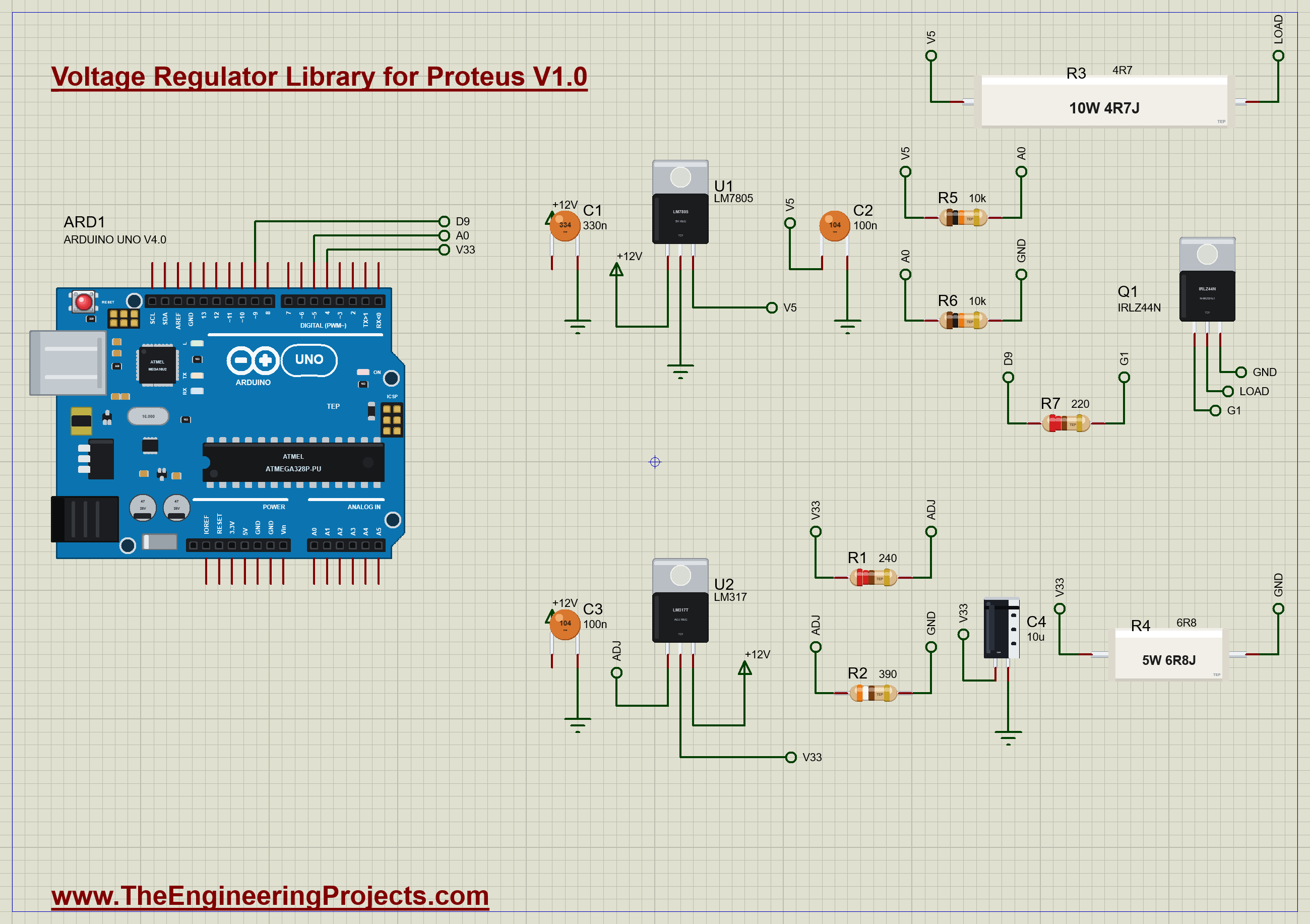
  ARD1:   Arduino UNO V4.0 running Regulator_Demo.hex, its serial monitor built in (window "TEP
  Arduino UNO - ARD1").
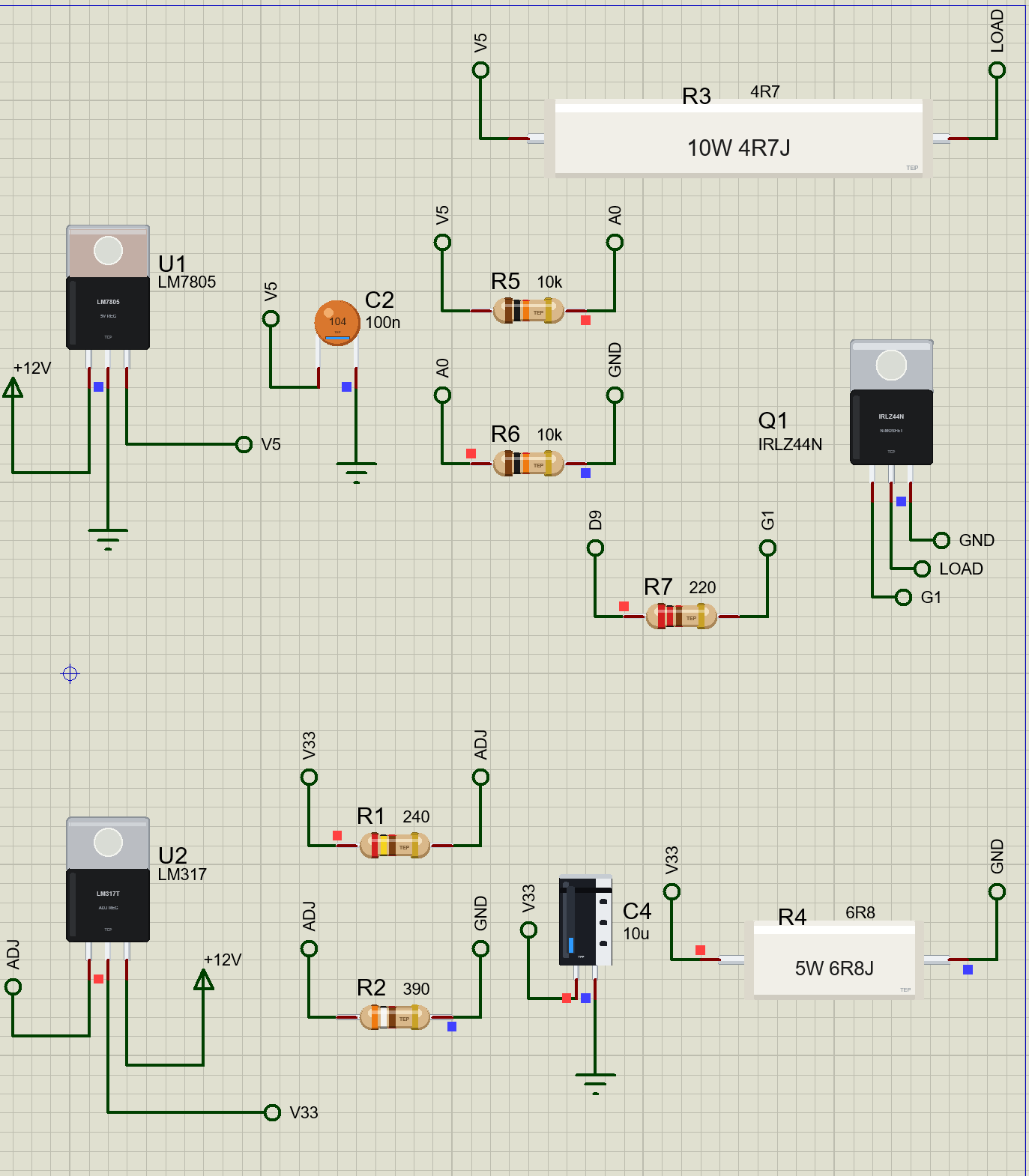
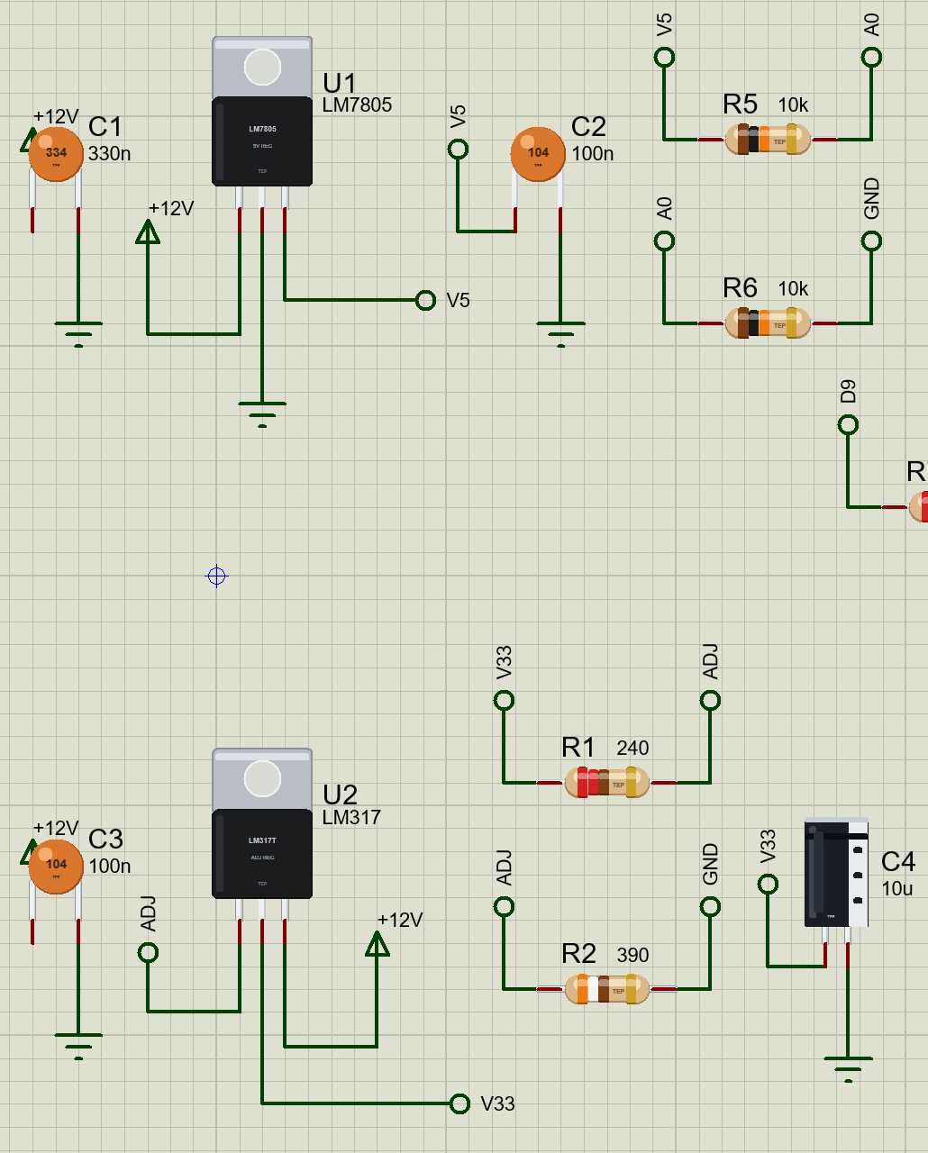
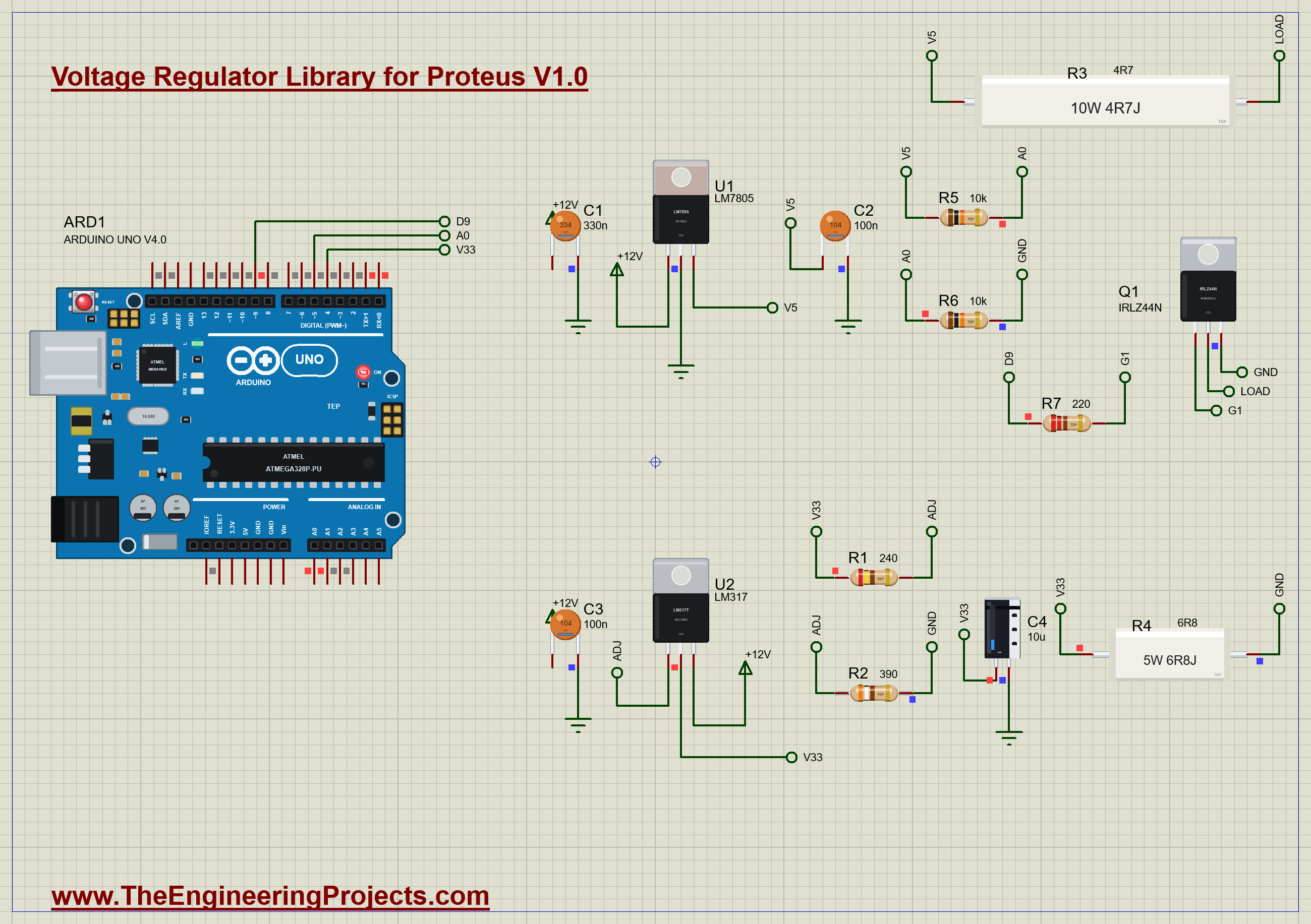
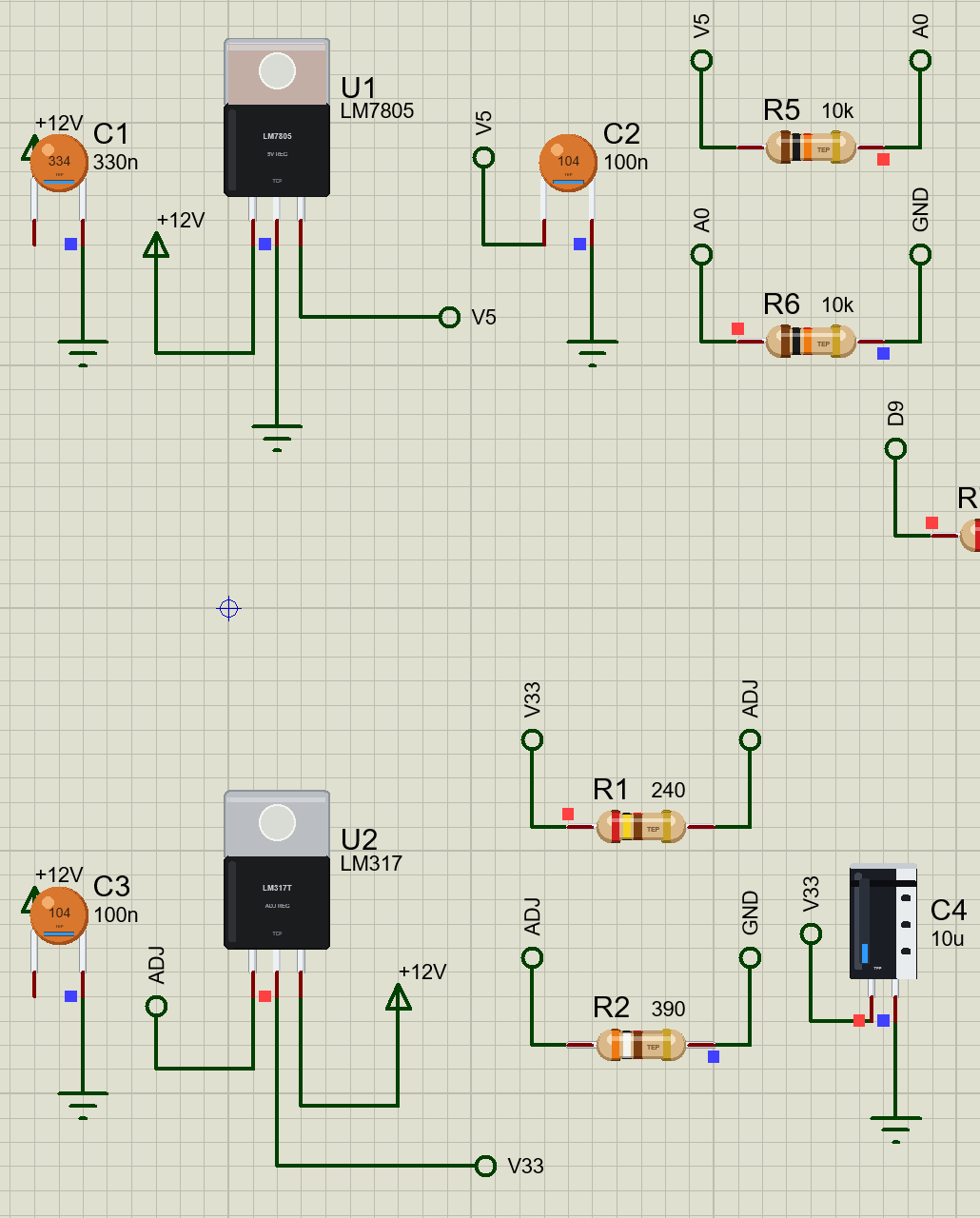
  U1 LM7805 (bare):     +12V - IN; C1 330n IN - GND; C2 100n OUT - GND; OUT = V5; R3 4R7 (10 W) from
  V5 to Q1 IRLZ44N (D9 - R7 220 - gate);
                        R5 / R6 10k from V5: A0 reads half of it
  U2 LM317 (LARGE):     +12V - IN; C3 100n; OUT = V33; R1 240 OUT - ADJ, R2 390 ADJ - GND: 3.3 V; C4
  10u; R4 6R8 (5 W) from V33 to GND; A1 on V33
  1. Press Run. The sketch prints both outputs every second; at 2 s it switches the 1 A load onto
  the LM7805.
  2. Watch U1's junction climb towards 150 C and its thermal shutdown cycle the output, while U2 on
  its heatsink stays cool.
Closed the monitor? Click the UNO's USB port.

WIRING (the same in Proteus and on a real board)
  LM7805: IN - 330 nF - GND, OUT - 100 nF - GND; the input at least 2 V over the output at 1 A
  LM317:  R1 (240) from OUT to ADJ, R2 from ADJ to GND: Vout = 1.25 V x (1 + R2 / R1) + 50 uA x R2;
  100 nF on IN, 1 uF or more on OUT
REAL HARDWARE:
 * Work out the heat first: (Vin - Vout) x I. A bare TO-220 sheds about 1 W to 1.5 W; more needs a
   heatsink.
 * Heatsink needed for a 125 C junction: (125 - 25) / P - 4 C/W (the junction to the tab) - and less
   for the thermal pad.
 * Keep the input about 2 V over the output at full current, and well under 35 V (LM7805) or 40 V
   (LM317).
 * Fit the input and output capacitors close to the legs.
 * From a high input at high current, a switching regulator wastes far less.

THE DEMO SKETCH ON THE SERIAL MONITOR (Regulator_Demo V1.0, 9600 baud)
There are no commands. The sketch switches the load on at 2 s and prints both outputs every second.
EXPECTED MONITOR OUTPUT
  Voltage regulators - The Engineering Projects
  t = 2 s: the 1 A load is switched onto the LM7805
  t = 13 s: LM7805 4.94 V, LM317 3.30 V
  t = 20 s: LM7805 4.93 V, on 37 % (too hot), LM317 3.30 V

PROPERTIES (double-click the part > Edit Properties)
  Part (VALUE)                     the label: LM7805 or LM317 (the device sets the regulator)
  Heatsink                         NONE (the bare tab: 54 C/W to the air in all), SMALL (19 C/W),
  LARGE (9 C/W)
Every run starts again from the properties.

LINKS.INI (OPTIONAL)
The Help page cards of the pop-up open web pages. To point them somewhere else without a new DLL,
put a text file named links.ini next to TEPREG.DLL with lines KEY=URL, for example:
  ARTICLE=https://www.theengineeringprojects.com/...
Keys: WEBSITE, FORUM, BUG_REPORT, FEATURE_REQUEST, ARTICLE, USER_GUIDE,
UPDATE_CHECK, DONATE. Only http:// and https:// links are used; lines starting
with # are comments.

TROUBLESHOOTING
* THERMAL CYCLING or SHUTDOWN: too much heat - a heatsink, less input voltage or less current.
* DROPOUT: the input is too close to the output; it needs about 2 V more at 1 A.
* CURRENT LIMIT: the load takes more than 2.2 A, or the output is shorted.
* The LM317's output creeps up with no load: it needs its minimum load - keep R1 at 240 ohm.
* The part is not simulated: TEPREG.DLL is missing from MODELS and from the project folder.
* The part is not simulated: TEPREG.DLL is missing from MODELS and from the project folder. No UNO /
  no monitor window: TEPARDUINO.DLL is missing, or click the UNO's USB port.

BUG REPORTS AND FEATURE REQUESTS
Please post them in our forum with a screenshot, the Serial Monitor text, the
simulation log and the pop-up's Copy diagnostics text:
  https://www.theengineeringprojects.com/forum/category/voltage-regulator-proteus-library

SUPPORT US
This library is free. If it saves you time, please support our work:
  https://www.theengineeringprojects.com/donate

WEBSITE
  https://www.theengineeringprojects.com/

LICENCES AND THIRD-PARTY NOTES
* The model (TEPREG.DLL), the symbols and artwork, the other parts of ours in the demo and the
  Arduino Library V4.0 (ArduinoV4TEP.LIB / TEPARDUINO.DLL, with its built-in TEP Serial Monitor
  Advance) are made by The Engineering Projects. The models use only standard Windows libraries; no
  Visual C++ redistributable is needed.
  The C++ source code is not included.
* Arduino UNO V4.0 (ArduinoV4TEP.LIB / TEPARDUINO.DLL, our Arduino Library V4.0 - its
  microcontroller is Proteus's own AVR model): The Engineering Projects,
  https://www.theengineeringprojects.com/2026/10/arduino-uno-library-for-proteus-v40.html
* The .hex file is built from the demo sketch and the Arduino AVR core 1.8.6, which includes
  LGPL-licensed code; its source code is available at
  https://github.com/arduino/ArduinoCore-avr/tree/1.8.6
* Proteus is a product of Labcenter Electronics and is not included. Arduino is a trademark of Arduino SA.
  This library is not made or endorsed by Arduino or Labcenter.

REBUILDING THE FIRMWARE (OPTIONAL)
The HEX file is supplied; Arduino IDE is not needed to run the demo. To edit the sketch, open
Arduino Code\Regulator_Demo\Regulator_Demo.ino, select Arduino Uno and use Sketch > Export Compiled
Binary. Replace the simulation's .hex with the exported HEX. The sketch needs 5,686 bytes of flash
and 230 bytes of RAM.

MODEL SCOPE AND LIMITS
Modelled: the set voltage with the line, load and temperature terms, the dropout, the current limit
with the LM317's foldback, the quiescent and
adjust-pin currents, the heat path junction - tab - air with its heat capacities, the thermal
shutdown.
Not modelled: the loop's speed and ripple rejection against frequency, the noise, reverse current
from OUT to IN. The heatsink values are typical, not
one datasheet.

VERSION
TEP Voltage Regulator library V1.0 (Nov 2026). Devices REG7805TEP and REGLM317TEP (TEPREG.LIB /
TEPREG.DLL). Demo sketch Regulator_Demo V1.0. Demo board: ARDUINO UNO V4.0 (TEP Arduino Library
V4.0) with its built-in serial monitor.Development1 release
 Development1 release
-
V1.0Voltage Regulator Library for Proteus V1.0this page
V1.0 is the only release in the Download Center so far. When a newer version is published, it appears above with its own download page.
Installation8 steps
 Installation8 steps
From the download to a working project, in order. The steps follow what the package contains.
You will need
- Proteus Design SuiteProteus 8 or newer (Labcenter), on Windows
- Arduino IDE1.8 or 2.x, with the board of the tutorial chosen under Tools → Board
- Any archive toolWindows, macOS and Linux extract ZIP files on their own
Steps
- 1
Extract the archive
Right-click voltage-regulator-tep-v1-0-addce0d7e8194a71bea3557634f4d09b.zip and choose Extract All (or open it with 7-Zip or WinRAR) into a folder you can find again. Keep its folder structure (Voltage-Regulator-TEP-v1.0) as it is.
- 2
Copy the library files into Proteus
Move ArduinoV4TEP.LIB, TEPCERAMIC.LIB and TEPELECTRO.LIB and 4 more and the files into the LIBRARY folder of your Proteus installation: C:\Program Files (x86)\Labcenter Electronics\Proteus 8 Professional\LIBRARY for Proteus 8, or the matching Proteus 7 folder. Older versions keep it under ProgramData\Labcenter Electronics. If Proteus is open, close it first.
- 3
Add the simulation model
Copy TEPARDUINO.DLL, TEPCERAMIC.DLL and TEPELECTRO.DLL and 4 more into the MODELS folder next to LIBRARY, so the component can run, not only be drawn.
- 4
Restart Proteus and place the component
Start Proteus, open a schematic, press P (Pick Devices) and search for the component by the name used in the tutorial. It appears with its pins ready to wire.
- 5
Open the sketch in the Arduino IDE
Open Regulator_Demo.ino, select your board and port under Tools, then Verify. Sketch → Export Compiled Binary writes the HEX file a simulation needs.
- 6
Load the HEX file
In Proteus double-click the microcontroller, set Program File to Regulator_Demo.hex and run the simulation. For real hardware, flash the same file with your programmer.
- 7
Open the example simulation
Open Voltage-Regulators-ArduinoUnoV4.pdsprj in Proteus to see the wiring exactly as in the tutorial. Check the controller's Program File path, then press Play.
- 8
Follow the tutorial
Voltage Regulator Library for Proteus: LM7805, LM317 explains every connection and setting in order; keep it open beside the files while you build.
FAQs9 questionsContact TEP
 FAQs9 questions
How do I download Voltage Regulator Library for Proteus V1.0?
Wait for the 30-second guest countdown on this page, then press the download button; the file comes straight from our storage. Members who are logged in skip the wait. If the browser opens the file instead of saving it, use its Save as option. The download link is made for you when the countdown ends and works for 15 minutes; a saved or shared link stops working, so share this page instead.
What is inside the archive?
Voltage Regulator Library for Proteus V1.0 comes as a ZIP archive of 25 files (2.8 MB, 6.1 MB unpacked) holding Proteus library files, simulation model DLLs, a Proteus simulation, an Arduino sketch and compiled HEX firmware. Open the File Structure tab for the full list of 25 files.
What should I do if the download does not start?
Check the browser's download list first; an ad blocker or a company firewall can also hold it back, so try another browser or network. If the file arrives incomplete, download it again. For an installation problem, read the Install tab or tell us in the comments with your software version and the exact error message.
Is this file free?
Yes. Every file in the TEP Download Center is free for learning, personal and student projects. If you share it, link back to this page or the tutorial so others find the latest version.
How do I check that the file arrived complete?
Compare its SHA-256 with the one on this page, 5ebae33fd25967b0eadb00e24c4752cecdda5faeaa36f885a13f36a8b4017f91. In PowerShell run Get-FileHash "voltage-regulator-tep-v1-0-addce0d7e8194a71bea3557634f4d09b.zip"; on macOS or Linux run shasum -a 256 "voltage-regulator-tep-v1-0-addce0d7e8194a71bea3557634f4d09b.zip". The same value means the file is exactly the one in our storage; a different one means the download broke off, so download it again.
Do I need WinRAR to open the ZIP file?
No. Windows, macOS and Linux open ZIP archives on their own (Extract All, or double-click). WinRAR and 7-Zip work too. Extract the whole archive before using the files.
Where do I put the LIB and IDX files?
Both files go into the LIBRARY folder of your Proteus installation (Proteus 8: C:\Program Files (x86)\Labcenter Electronics\Proteus 8 Professional\LIBRARY; Proteus 7 has the same folder under its own name). Restart Proteus afterwards and search for the component with P.
Which Proteus version does the library need?
The tutorial names the Proteus version the library was made and tested with. Most TEP libraries work in Proteus 7 and Proteus 8; if the component does not appear after a restart, check that both the LIB and the IDX file were copied and that Proteus was fully closed while copying.
How do I get the HEX file into the simulation?
Compile the sketch in the Arduino IDE (Sketch → Export Compiled Binary gives you the HEX next to the sketch), then in Proteus double-click the board, set Program File to that HEX and run.
Members skip the wait. Log in or join TEP.

- 0Total downloads
- 4%Popularity
- ProteusCategory
- 0Comments
- ssyedzainnasirUploaded by
- 9 Nov 2026Uploaded at


 SHA-256
5ebae33fd25967b0eadb00e24c4752cecdda5faeaa36f885a13f36a8b4017f91


 Need help with this file?
 Tags
Related Proteus
All Proteus tutorials


Comments
0