STM32 SPI Communication


The SPI (Serial Peripheral Interface) protocol, or rather the SPI interface, was originally devised by Motorola (now Freescale) to support their microprocessors and microcontrollers. Unlike the I2C standard designed by Philips, the SPI interface has never been standardized; nevertheless, it has become a de-facto standard. National Semiconductor has developed a variant of the SPI under the name Microwire bus. The lack of official rules has led to the addition of many features and options that must be appropriately selected and set in order to allow proper communication between the various interconnected devices. The SPI interface describes a single Master single Slave communication and is of the synchronous and full-duplex type. The clock is transmitted with a dedicated line (not necessarily synchronous transmission that has a dedicated line for the clock) and it is possible to both transmit and receive data simultaneously. The figure below shows a basic connection diagram between two peripherals that make use of the SPI interface.

From the figure, it is immediately possible to notice what has just been said, namely that the communication generally takes place between a Master and a Slave. The interface presents 4 connection lines (excluding the ground however necessary), for which the standard SPI is also known as 4 Wire Interface. The Master starts the communication and provides the clock to the Slave. The nomenclature of the various lines in the SPI interface is normally as follows:
- MOSI: Master Output Slave In. Through this line the master sends the data to the selected slave;
- MISO: Master Input Slave Output. Through this line the slave sends the data to the master;
- SCLK: Serial Clock is generated by the master device, so it is the master starts the communication and the clock synchronizes the data transfer over the bus. The SPI clock speed is usually several MHz (today up to 100 MHz);
- SS: Slave Select or CS (Chip Select) generated by the master to choose which slave device it wants to communicate with (it must be set to a low logic level). SS (or CS) is not indispensable in all applications.
In addition to this standard nomenclature, there are other acronyms.
For example:- The MOSI line is also called: SDO (Serial Data Out), DO (Data Out), DOUT and SO (Serial Out)
- The MISO line is also called: SDI (Serial Data In), DI (Data In), DIN and SI (Serial In)
- The Clock line is also called: CLK, SCK (Serial Clock).
- The Enable line is also called: CS (Chip Select), CE (Chip Enable)
The first advantage in SPI communication is faster communication, instead, the first disadvantage is the presence of the SS pin necessary to select the slave. It limits the number of slave devices to be connected and considerably increases the number of lines of the master dedicated to SPI communication as the connected slaves increase.
To overcome these problems, the devices in the daisy chain can be connected (output of a device connected to the input of the next device in the chain) as shown in the figure below where a single slave selection line is used.

The disadvantages, however, are the lower updating speed of the individual slaves and signal interruption due to the failure of an element.
We can use this communication to put in communication our micro-controller with different peripherals as Analog-Digital Converters (ADCs), Digital-Analog Converters (DACs), EEPROM memories, sensors, LCD screen, RF module, Real Time Clock, etc.
The STM32 micro-controllers provide up to 6 SPI interfaces based on the type of package that can be quickly configured with STCube Tool.
STCube Tool initializes the peripherals with HAL (Hardware Abstraction Layer) library. The HAL library creates for SPI (as all peripherals) an C structure:
- struct SPI_HandleTypeDef

- • Instance: is the pointer variable it describes the SPI that we want to use. If we use SPI1, the name of the instance is SPI1.
- • Init: is an instance that points to the structure ( SPI_InitTypeDef) used to initialize the device. We will discuss the structure SPI_InitTypeDef shortly.
- • pTxBuffPtr, pRxBuffPtr: are pointer variables that point to an internal buffer. They are used to store the data during the communication when the programmer handles the SPI in interrupt mode (we will see forward)
- • hdmatx, hdmarx: are the pointer variable to instances of the DMA_HandleTypeDef struct. They are used when the programmer handles the SPI in DMA mode (will see forward).
As just said to initialize the SPI peripheral to be used, it is necessary to use the struct SPI_InitTypeDef. It is defined as follow:

When we use the STcubeMX to initialize the SPI peripheral we are modifying this structure
In details:- Mode specifies the SPI operating mode, and Direction specifies the SPI bidirectional mode state. It is very easy to configure in STCubeMx. If we want to configure the SPI1. We can find SPI windows in Pinout&Configuration -> Connectivity. Here we can select between the SPI available. Now is possible to select the communication mode (Master, Slave, half-duplex, full-duplex, etc.) as follow:

If the slave supports, the full-duplex communication can be enabled.
- DataSize indicates the SPI data size. The user can select 8bit or 16bit.

- CLKPolarity defines if the serial clock steady state is LOW or HIGH.

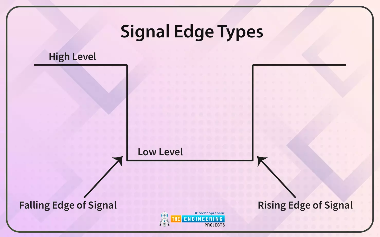
- CLKPhase defines if the bit capture (trigger) takes place when the clock is on the falling edge or rising edge.

- NSS: if selected "Output Hardware" the slave select signal is managed by hardware otherwise is managed by software using the SSI bit.

- BaudRatePrescaler can be select the Baud Rate prescaler value.

- FirstBit indicates if data transfers start from Most Significant Bit (MSB) or Last Significant Bit (LSB).
- TIMode specifies if the TI mode is enabled or not.

- CRCCalculation: to enable to activate the CRC calculation.
- CRCLength: to define the length of CRC data.
- CRCPolynomial specifies the polynomial (X0+X1+X2) used for the CRC calculation. This parameter is an odd number 1 and 65535.

By enabling the SPI and the chip select pin, the pins available on the microcontroller are automatically chosen to manage this interface (but they can be changed by looking for the alternative functions of the different pins of the microcontroller). For example, in our case the following pins are selected:
- PA4 SP1_NSS
- PA5 SP1_SCK
- PA6 SP1_MISO
- PA7 SP1_MOSI
Now you can generate the initialization code. Before being able to write the first code to manage this communication interface, it is necessary to understand the functions that the libraries provide and the different communication modes.
As for other communication interfaces, the HAL library provides three modes to communicate: polling mode, interrupt mode, and DMA mode.
STM32 SPI Communication in Polling Mode
Using the SPI in Polling Mode is the easiest way, but it is the least efficient way as the CPU will remain in a waiting state for a long time. HAL library provides the following functions to transmit and receive in polling mode:
- HAL_SPI_Receive(SPI_HandleTypeDef *hspi, uint8_t *pData, uint16_t Size, uint32_t Timeout)
Master receives data packets in blocking mode (polling mode).
The parameters are:
- hspi is a pointer to a “SPI_HandleTypeDef” structure. “SPI_HandleTypeDef” structure includes the configuration information for SPI module.
- pData is a pointer to data buffer
- Size is the amount of data to be sent
- Timeout is the timeout duration
- HAL_SPI_Transmit(SPI_HandleTypeDef *hspi, uint8_t *pData, uint16_t Size, uint32_t Timeout)
Master transmits data packets in blocking mode (polling mode).
If the slave device supports, the full-duplex mode:
- HAL_SPI_TransmitReceive(SPI_HandleTypeDef *hspi, uint8_t *pTxData, uint8_t *pRxData, uint16_t Size, uint32_t Timeout)
Master transmits and receives data packets in blocking mode (polling mode).
The parameters are:
- hspi is a pointer to a “SPI_HandleTypeDef” structure. “SPI_HandleTypeDef” structure includes the configuration information for SPI module
- pTxData is a pointer to transmission data buffer
- PRxData is a pointer to reception data buffer
- Size is the amount of data to be sent
- Timeout is the timeout duration
STM32 SPI Protocol in Interrupt Mode
Using the SPI in Interrupt Mode, also called non-blocking mode. In this way, the communication can be made more effective by enabling the interrupts of the SPI in order to receive, for example, signals when the data has been sent or received. This improves CPU time management. In applications where all the management must be deterministic and it is not known when an interrupt can arrive, these can potentially manage the time management of the CPU, especially when working with very fast buses such as SPI. We can enable the SPI interrupts directly during the initialization with STCube Mx.
HAL library provides the following functions to transmit and receive in interrupt mode:
- HAL_SPI_Receive_IT(SPI_HandleTypeDef *hspi, uint8_t *pData, uint16_t Size)
- hspi is a pointer to a “SPI_HandleTypeDef” structure. “SPI_HandleTypeDef” structure includes the configuration information for SPI module
- pData is a pointer to data buffer
- Size is the amount of data to be sent
void HAL_SPI_RxCpltCallback(SPI_HandleTypeDef * hspi) { // Message received .. Do Something ... }
- HAL_SPI_Transmit_IT(SPI_HandleTypeDef *hspi, uint8_t *pData, uint16_t Size)
Master transmits data packets in blocking mode (interrupt mode).
To handle the interrupt needs to write our code in the callback:
void HAL_SPI_TxCpltCallback(SPI_HandleTypeDef * hspi) { // Message transmitted.... Do Something ... }If the slave device supports, the full-duplex mode:
- HAL_SPI_TransmitReceive_IT(SPI_HandleTypeDef *hspi, uint8_t *pTxData, uint8_t *pRxData, uint16_t Size)
Master transmits and receives data packets in non-blocking mode (interrupt mode).
To handle the interrupt needs to write our code in the callback:
void HAL_SPI_TxRxCpltCallback(SPI_HandleTypeDef * hspi) { // Message transmitted or received.. .. Do Something ... }
STM32 SPI Communication in DMA Mode
Using the SPI in DMA Mode the SPI bus can be used at its maximum speed, in fact, since the SPI must store the received and transmitted data in the buffer to avoid overloading it is necessary to implement the DMA. In addition, use by DMA mode frees the CPU from performing "device-to-memory" data transfers. We can easily configure the DMA during the initialization using STCubeMx :

In this case, the DMA is enabled in normal (we can use it in circular mode) mode both in transmission and reception
HAL library provides the following functions to transmit and receive in DMA mode:
- HAL_SPI_Receive_DMA(SPI_HandleTypeDef *hspi, uint8_t *pData, uint16_t Size)
Master receives data packets in non-blocking mode (DMA mode).
The SPI device receives all bytes of data in the buffer one by one until the end in DMA mode. At this point, the callback function will be called and executed where something can be done.
void HAL_SPI_RxCpltCallback(SPI_HandleTypeDef * hspi) { // Message received .. Do Something ... }
- HAL_SPI_Transmit_DMA(SPI_HandleTypeDef *hspi, uint8_t *pData, uint16_t Size)
Master transmits data packets in non-blocking mode (DMA mode).
The SPI device sends all bytes of data in the buffer one by one until the end in DMA mode. At this point, the callback function will be called and executed where something can be done.
void HAL_SPI_TxCpltCallback(SPI_HandleTypeDef * hspi) { // Message transmitted….. Do Something ... }
If the slave device supports, the full-duplex mode:
- HAL_SPI_TransmitReceive_DMA(SPI_HandleTypeDef *hspi, uint8_t *pTxData, uint8_t *pRxData, uint16_t Size,)
Master transmits and receives data packets in non-blocking mode (DMA mode).
The SPI device sends or receives all bytes of data in the buffer one by one until the end in DMA mode. At this point, the callback function will be called and executed where something can be done.
void HAL_SPI_TxRxCpltCallback(SPI_HandleTypeDef * hspi) { // Message transmitted or received.... Do Something ... }
We are now ready to handle an SPI communication with STM32.