Hello friends, I hope you all are doing great. Today, I am going to share the new PN532 NFC Library for Proteus V1.1. The PN532 is NXP's NFC controller for 13.56 MHz cards and tags, best known on the red Elechouse PN532 NFC RFID module V3. With this PN532 NFC Library for Proteus, you place cards on the reader with a click, and your Arduino reads them over SPI or I2C with the same Adafruit PN532 library you use on real hardware.
PN532 NFC Library for Proteus
Latest version: V1.1 (September 2026, this tutorial)
Other RFID / NFC readers: MFRC522 · EM18
Helping Tools
- Serial Monitor Advance: a serial terminal window for the UART of your board
- Serial Monitor Expert: the serial monitor with extra debugging tools
- LCD Library for Proteus V3.0: 16x2, 20x4 and I2C LCDs to show your readings
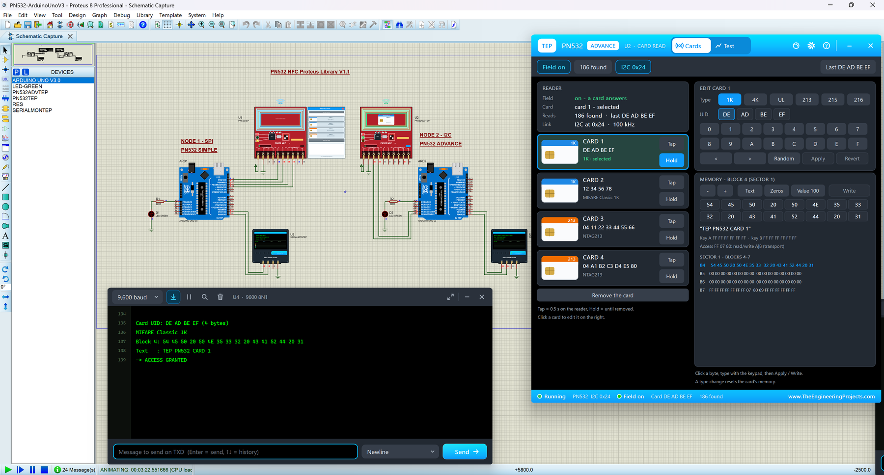
Version 1.1 replaces the first version of this post. You now get two devices: PN532 Simple, with a card panel on the schematic, and PN532 Advance, with a pop-up card wallet and four measured NFC test tools. The new PN532 Arduino Proteus demo is an access-control system on two Arduino UNOs, one reader on SPI and one on I2C, shown in the compact Simple interface of our TEP Serial Monitor. Have you read version 1.0? Then jump to "What's New" below.
NOTICE: This library is very special to our team. Our PN532 model speaks the chip's frame protocol over SPI, I2C and HSU, and its MIFARE and NTAG cards answer like real ones, down to the time every command takes. It took our team a lot of hard work, many test runs and many design changes. Your feedback is the fuel that keeps us going, so please tell us what you think in the comments below or in the PN532 Library board of our forum. And if our free libraries help you, you can buy us a coffee. So, let's get started with the PN532 NFC Library for Proteus:
What is the PN532 NFC Module?
The PN532 is an NFC controller made by NXP for 13.56 MHz cards and tags. It runs its own firmware: your Arduino sends complete commands, such as "find a card" or "read block 4", and the chip does the radio work. It talks to the Arduino over SPI, I2C or HSU (High Speed UART, a serial port).
The popular red Elechouse V3 board carries a large PCB antenna coil, the PN532 with its 27.12 MHz crystal, a mode switch that selects the interface, two pin headers and a power LED. It is used for door locks, attendance systems and NFC stickers.
NFC and RFID: What Is the Difference?
RFID (radio-frequency identification) is the big family: the reader sends out a radio field, and a tag without a battery takes its power from it and answers, at 125 kHz (our EM18 reader) or 13.56 MHz (MIFARE cards). NFC (near field communication) is the 13.56 MHz branch built on ISO/IEC 14443, for a few centimetres. So every NFC tag is an RFID tag, but a 125 kHz tag can't be read by an NFC reader. NFC also adds a data format, NDEF, that any phone can read.
The PN532 at a Glance
| Feature | Value |
|---|---|
| Frequency | 13.56 MHz |
| Cards | ISO/IEC 14443 type A at 106 kbit/s; our model: MIFARE Classic 1K / 4K, MIFARE Ultralight, NTAG213 / 215 / 216 |
| Host interfaces | SPI (mode 0, least significant bit first), I2C at address 0x24, HSU (UART, 115200 baud) |
| Firmware | Version 1.6 (GetFirmwareVersion answers 32 01 06 07) |
| Ready signal | The IRQ pin is LOW while an answer is ready; a RDY byte on I2C, a status read on SPI |
| Reset | RSTPDN: LOW = reset / power-down |
| Supply (V3 board) | 3.3 V or 5 V: the board has its own 3.3 V regulator |
| Range | 5 - 7 cm with the board's PCB antenna (Elechouse data) |
PN532, MFRC522 or EM18: Which Library Do You Need?
| Your reader | Cards and interface | Our library |
|---|---|---|
| PN532 NFC (red Elechouse V3 board) | 13.56 MHz MIFARE Classic, Ultralight and NTAG; SPI, I2C or HSU; the chip's firmware does the card work | This article |
| RFID-RC522 (MFRC522) | 13.56 MHz MIFARE Classic, Ultralight, NTAG213; SPI; the Arduino drives the chip's registers | MFRC522 RFID Library for Proteus |
| EM18 | 125 kHz tags; serial (UART) output | EM18 RFID Library for Proteus |
NFC Terms You Will See in This Article
| Term | Meaning |
|---|---|
| UID | The card's unique number: 4 bytes on a MIFARE Classic, 7 bytes on Ultralight and NTAG |
| SENS_RES, SEL_RES | The card's 2-byte answer to the reader's request and its 1-byte answer to SELECT (also called ATQA and SAK); SEL_RES tells the card type |
| Block, sector | A MIFARE Classic stores blocks of 16 bytes; four blocks form a sector |
| Key A, key B, access bits | The two 6-byte keys of a sector and the bytes that say which key may read or write which block |
| Page | The 4-byte memory unit of Ultralight and NTAG cards |
| NDEF | NFC Data Exchange Format: the message a phone reads, for example a web address |
| Frame, ACK | The packet that carries a command or an answer, and the short "got it" frame |
| RDY byte, IRQ | How the PN532 says "my answer is ready": a status byte on I2C, a LOW level on the IRQ pin |
| InListPassiveTarget, InDataExchange | The PN532 commands 4A and 40: find a card, send a command to it |
How the PN532 Talks to Your Arduino
The PN532 receives whole commands in frames, not register by register like the MFRC522.
SPI, I2C or HSU: The Mode Switch
The PN532 listens on one interface at a time, chosen by two pins it reads at reset. On the V3 board, they are the two slide switches of the mode switch, with this table printed beside them:
| Interface | Switch 1 | Switch 2 | Arduino pins in our demo |
|---|---|---|---|
| HSU (UART, 115200 baud) | 0 (OFF) | 0 (OFF) | Not used (needs a Mega's Serial1) |
| I2C (address 0x24) | 1 (ON) | 0 (OFF) | SCL A5, SDA A4 |
| SPI | 0 (OFF) | 1 (ON) | SCK D13, MISO D12, MOSI D11, SS D10 |
SPI needs four wires and is the fastest, I2C needs two, and HSU is a serial port. In the simulation, the property MODE plays the switch: AUTO, the default, answers on SPI and I2C at once, while SPI, I2C or HSU keep only that interface.
The PN532 Frame and Its ACK
Every command travels in a frame, such as the firmware-version request every sketch sends first:
00 00 FF 02 FE D4 02 2A 00| Bytes | Meaning |
|---|---|
| 00 00 FF | Preamble and start code: a frame begins |
| 02 FE | The length (2 bytes follow) and its check byte: 02 + FE = 100 hex |
| D4 02 | D4 = from the host to the PN532 (answers carry D5); 02 = GetFirmwareVersion |
| 2A 00 | The data check byte (D4 + 02 + 2A = 100 hex) and the postamble |
The PN532 answers in two steps. First comes a short ACK frame, 00 00 FF 00 FF 00, "I got it", ready 0.3 ms after the frame in our model. When the work is done, the response follows: 00 00 FF 06 FA D5 03 32 01 06 07 E8 00, where 32 means PN532 and 01 06 is firmware 1.6. To know when an answer is ready, the Arduino reads a status byte on SPI or the RDY byte that starts every I2C read (01 = ready), or watches the IRQ pin go LOW. The Adafruit library polls, waiting 10 ms between checks.
Why I2C Is Slower than SPI
In our demo, SPI runs at 1.00 MHz and I2C at 100 kHz. An SPI byte takes 8 clock pulses (8 us). An I2C byte takes 9, the 8 bits plus an acknowledge bit (90 us), and every I2C transfer adds a start, the address byte and a stop. So reading the 20-byte answer of a card search plus its RDY byte takes about 2 ms on I2C, but about 0.2 ms on SPI. I2C still works well, but in Proteus, which runs the two UNOs slower than real time, U4's lines can come a few seconds after your click.
How the PN532 Reads a Card
Finding a Card: InListPassiveTarget
The Adafruit function readPassiveTargetID() sends InListPassiveTarget (command 4A) in an 11-byte frame, 00 00 FF 04 FC D4 4A 01 00 E1 00: one card, 106 kbit/s type A. The PN532 switches its RF field on and looks for a card. For CARD 1 it answers:
D5 4B 01 01 00 04 08 04 DE AD BE EFThat is one target, number 1, SENS_RES 00 04, SEL_RES 08 (a MIFARE Classic 1K) and a 4-byte UID, DE AD BE EF. With no card, the PN532 tries again every 2 ms in our model; the demo allows 17 tries, so "no card" comes after 34 ms.
4-Byte and 7-Byte UIDs
A MIFARE Classic has a 4-byte UID, read in one round (a cascade level). Ultralight and NTAG cards have a 7-byte UID, which needs two rounds, so our model finds them in 4.7 ms instead of 2.8 ms. A 7-byte NXP UID starts with 04, NXP's manufacturer code, as in CARD 3 (04 11 22 33 44 55 66). The demo sketch tells the two families apart by the UID length.
MIFARE Classic Memory: Sectors, Blocks, Keys and Access Bits
A MIFARE Classic 1K has 16 sectors of 4 blocks of 16 bytes (1024 bytes); the 4K has 32 sectors of 4 blocks plus 8 of 16. Block 0 holds the UID and is read-only. The last block of each sector is its sector trailer: key A, the access bits and key B, in our cards FF FF FF FF FF FF, FF 07 80 69 and FF FF FF FF FF FF. The demo text lives in block 4, in sector 1.
Before reading a block, the reader must authenticate its sector with key A or key B, and the access bits decide what each key may do. A surprise of the transport setting FF 07 80: key B is readable there, and a readable key B can't be used, so every read after it gets error 14, as our model enforces.
MIFARE Ultralight and NTAG213 / 215 / 216
Ultralight and NTAG cards have a 7-byte UID, pages of 4 bytes and no sector keys (Ultralight 16 pages, NTAG213 45, NTAG215 135, NTAG216 231). Page 3, the capability container, reads E1 10 12 00 on CARD 3: E1 marks an NDEF tag, and 12 hex = 18 gives the user memory in units of 8 bytes, 144 bytes for an NTAG213 (3E means 496 bytes, 6D 872). The library can't tell an NTAG213 from an Ultralight, so the v1.1 demo reads this byte.
NDEF: The Message a Phone Reads
An NFC phone looks for an NDEF message from page 4 on, stored as TLV blocks (type, length, value). CARD 3 starts with these 16 bytes, printed by the demo as "Pages 4-7":
01 03 A0 10 44 03 1F D1 01 1B 55 02 74 68 65 65| Bytes | Meaning |
|---|---|
| 01 03 A0 10 44 | A lock-control TLV, 3 bytes long; the sketch skips it |
| 03 1F | The NDEF message TLV: 1F = 31 bytes |
| D1 01 1B 55 | Record header (one short, well-known record), type length 1, payload 27 bytes, type 55 = "U" (URI) |
| 02 | The prefix code for "https://www." |
| 74 68 65 65 ... | "thee": the start of the 26 characters of theengineeringprojects.com; an FE byte ends the data |
So a phone opens https://www.theengineeringprojects.com. CARD 4 holds an empty NDEF message, and the demo's NDEF command writes a new link to the card on the reader.
What's New in PN532 NFC Library for Proteus V1.1
If you used version 1.0, here is what has changed:
- Two devices in
TEPPN532.LIB: PN532 Simple (PN532TEP, the v1.0 device, so old designs keep working) and PN532 Advance (PN532ADVTEP) with a pop-up window. - A redrawn, live board: the red Elechouse V3 look with a big antenna coil that glows cyan (field on) or green (a card answers), the card drawn on the antenna, a mode switch that follows your interface and CARD and IRQ LEDs beside PWR. The 10 pins keep their v1.0 names, order and positions.
- Close and reopen the panels; a card wallet, card editor and four measured test tools on the Advance.
- Real timing: air time at 106 kbit/s; a card that does not answer is given up after the PN532's own 51.2 ms timeout (v1.0: 25 ms); an empty search try takes 2 ms (v1.0 estimated 4 ms).
- More cards: Classic 4K, Ultralight, NTAG215 and NTAG216, with keys and access bits enforced in every sector trailer.
- HSU: the property MODE (AUTO, SPI, I2C or HSU) plays the real switch.
- One two-UNO demo (SPI + I2C) with access LEDs, new commands and the TEP Serial Monitor, instead of two one-UNO projects with a Virtual Terminal.
- Lighter package: about 1.5 MB, without the C++ source code (v1.0: about 7.4 MB).
PN532 NFC Library for Proteus: Simple vs Advance
Both devices run the same PN532 model with the same properties; only the panel differs:
| Feature | Simple | Advance |
|---|---|---|
| Full PN532 model (SPI, I2C, HSU, frames, IRQ, RSTPDN, six card types) | ✔ | ✔ |
| Red V3 board: live antenna, card on the antenna, mode switch, PWR / CARD / IRQ LEDs | ✔ | ✔ |
| Card panel on the schematic (CARD 1 - 4, REMOVE CARD, last commands) | ✔ | ✘ |
| Card wallet in a pop-up window you can move, resize and minimise | ✘ | ✔ |
| Tap (0.5 s) and Hold for every card | ✘ | ✔ |
| Card editor: type, UID keypad, memory, keys, access bits and NDEF | ✘ | ✔ |
| Read test, Card types, Authentication and Frames | ✘ | ✔ |
| TEP Dark / Light theme, text size, Help page with Copy diagnostics | ✘ | ✔ |
| Same device name as v1.0 (old designs keep working) | ✔ | ✘ |
Choose Simple to keep the cards beside your circuit, and Advance when your sheet is full or you want hard numbers about your NFC code.
Download PN532 NFC Library for Proteus
Click the button below to download PN532-NFC-Library-for-Proteus-v1.1.zip (about 1.5 MB, without the C++ source code):
PN532 NFC Library for Proteus V1.1- README.txt: the full guide, from the wiring to real hardware.
- Proteus Library Files:
TEPPN532.LIB(both devices),TEPSERIALMON.LIBand our Arduino UNO libraryArduinoV3TEP.LIB/ArduinoV3TEP.IDX. - Proteus Model Files:
TEPPN532.DLLandTEPSERIALMON.DLL. - Proteus Simulation:
PN532-ArduinoUnoV3.pdsprj,PN532_SPI_Demo.hex,PN532_I2C_Demo.hexand copies of both DLLs. - Arduino Code:
PN532_SPI_Demo.ino,PN532_I2C_Demo.ino, the Adafruit PN532 library 1.3.4 by Adafruit Industries (with its examples; BSD licence, license.txt) and Adafruit BusIO 1.17.4 (MIT licence, LICENSE), both unmodified.
No Proteus yet? Read How to Download and Install Proteus 7 and 8. New to libraries? Follow How to Install a New Library in Proteus.
How to Install PN532 NFC Library for Proteus
- Close Proteus and extract the whole zip file.
- Copy the four files from Proteus Library Files into the LIBRARY folder, usually
C:\Program Files (x86)\Labcenter Electronics\Proteus 8 Professional\LIBRARY(on some PCsC:\ProgramData\Labcenter Electronics\Proteus 8 Professional\LIBRARY). - Copy
TEPPN532.DLLandTEPSERIALMON.DLLinto the MODELS folder. - Start Proteus, press P and search for PN532. You get the Simple and the Advance device (category Peripherals > Wireless).
Updating from v1.0? Replace TEPPN532.LIB and TEPPN532.DLL, and delete TEPPN532.IDX if there is one in LIBRARY. A v1.0 design keeps its v1.0 symbol and runs with the new model, with the v1.0 panel (no new board parts, no red X); re-pick the part to get the v1.1 board. Tested in Proteus 8.5; Proteus 7 is not supported.
The PN532 Board in Proteus
We designed the reader as a clean TEP board in the red of the Elechouse V3: four turns of the antenna coil, the PN532 and its crystal, the mode switch with its table, three LEDs, the PANEL button and a SIMPLE or ADVANCE badge. Here is U1, the Simple device on SPI, with CARD 1:
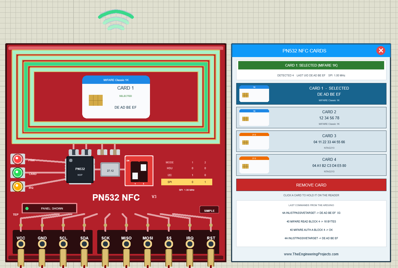
The coil and the waves are green, because the card has just answered, and CARD 1 is drawn on the antenna with its state and UID. PWR, CARD and IRQ are lit, and the SPI row shows the clock measured on the SCK pin: SPI 1.00 MHz.
Pinout
The ten Proteus pins keep the v1.0 order. A real V3 board has a 4-pin header (GND VCC SDA SCL) and an 8-pin header (SCK MISO MOSI SS VCC GND IRQ RSTO), so always wire by the names:
| Pin | Function | Demo connection |
|---|---|---|
| VCC | Power (3.3 V or 5 V on a real V3 board) | Supply terminal |
| GND | Ground | GND |
| SCL | I2C clock; in HSU mode RXD (from the host's TX) | U2: Arduino A5 |
| SDA | I2C data; in HSU mode TXD (to the host's RX) | U2: Arduino A4 |
| SCK | SPI clock from the Arduino | U1: Arduino D13 |
| MISO | SPI data from the PN532 | U1: Arduino D12 |
| MOSI | SPI data to the PN532 | U1: Arduino D11 |
| SS | SPI chip select, active LOW | U1: Arduino D10 |
| IRQ | LOW while an answer is ready | Not connected |
| RST | RSTPDN: LOW = reset / power-down | Not connected |
Antenna, Card and LEDs
| Indicator | What it shows |
|---|---|
| Antenna coil | Copper = RF field off, cyan = field on, green = a card answers; the waves above it follow |
| Card on the antenna | The type band, CARD n, the state and the UID; "PLACE A CARD HERE · 13.56 MHz NFC" when empty |
| PWR LED (red) | VCC and GND are connected |
| CARD LED (green) | Lights for 0.35 s (simulation time) after every card answer |
| IRQ LED (amber) | Lit while the IRQ pin is LOW: the PN532 has an answer ready |
| Mode switch and table | The knobs and the highlighted row show SPI, I2C or HSU, with the clock under the table |
| PANEL / OPEN PANEL, SIMPLE / ADVANCE | The panel button and the device badge |
CARD and IRQ are TEP additions: the real V3 board has only its power LED.
The Mode Switch Follows Your Sketch
In the simulation, the board shows the interface your Arduino really uses: SPI on U1, I2C on U2. With the property MODE set to HSU, both knobs go down:
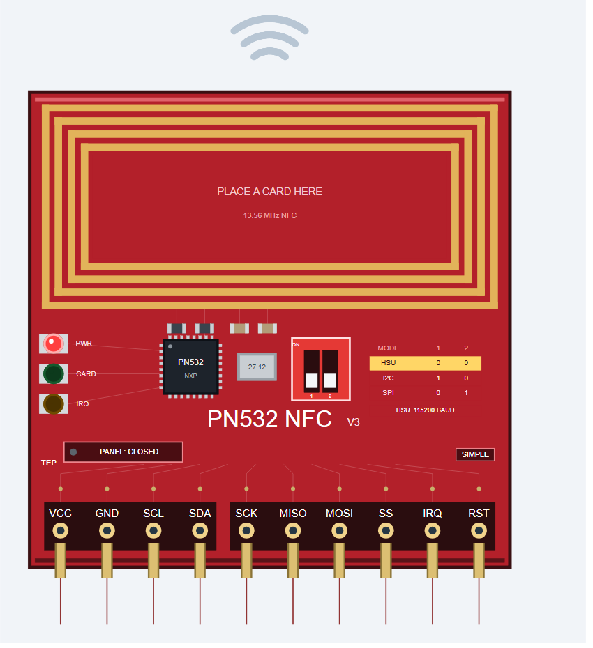
The coil stays copper until the first command switches the RF field on. HSU was tested on the PC only: the UNO's serial port is busy with the Serial Monitor, so use a Mega's Serial1.
PN532 Simple: The Card Panel on the Sheet
Beside the Simple board sits the PN532 NFC CARDS panel (see the image above):
| Part | What it does |
|---|---|
| Header, red X | PN532 NFC CARDS; the X closes the panel |
| State bar | For example CARD 1: SELECTED (MIFARE 1K), NOT SET UP - SKETCH: begin() or NO POWER |
| Counter line | DETECTED (how often the reader found a card), LAST UID and the interface with its clock |
| CARD 1 - CARD 4 | Click one to hold it on the reader; the band shows the type, the card on the reader is dark blue |
| REMOVE CARD | Takes the card away |
| LAST COMMANDS FROM THE ARDUINO | The newest commands, decoded, newest at the top; repeats are folded as X n |
CARD 1: The Last Commands from the Arduino
Read U1's command list after CARD 1 from the bottom up, and you watch the sketch at work:
- 4A INLISTPASSIVETARGET -> DE AD BE EF: the PN532 found CARD 1.
- 40 MIFARE AUTH A BLOCK 4 -> OK: key A opened sector 1.
- 40 MIFARE READ BLOCK 4 -> 16 BYTES: the demo text.
- 4A INLISTPASSIVETARGET -> DE AD BE EF X3: three more searches found the card still there.
U3 printed ACCESS GRANTED, and D1 lit for 3 s. DETECTED keeps growing while the card stays.
CARD 3: An NTAG213 with a Web Link
Now click CARD 3, the orange NTAG213 with a 7-byte UID:
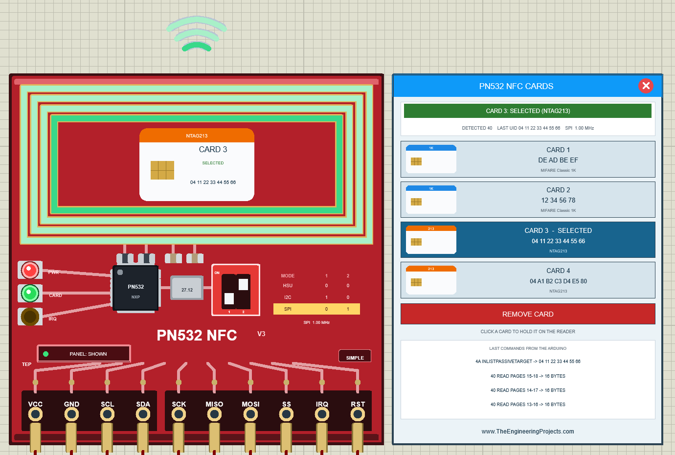
No AUTH this time: NTAG pages need no key. The sketch reads page 3 and pages 4 to 15, and each READ returns 16 BYTES, because an NTAG READ always sends 4 pages (hence READ PAGES 15-18). U3 printed the NDEF link and ACCESS GRANTED.
CARD 2, CARD 4 and REMOVE CARD
CARD 2 (12 34 56 78), a Classic 1K, is not on the allowed list: ACCESS DENIED. CARD 4, an NTAG213, gives "NDEF: empty message" and ACCESS DENIED. REMOVE CARD takes the card away, and the sketch prints "Card removed".
Closing the Panel
Need room? Click the red X: the board button says PANEL: CLOSED, and the reader keeps running. PANEL brings the panel back.
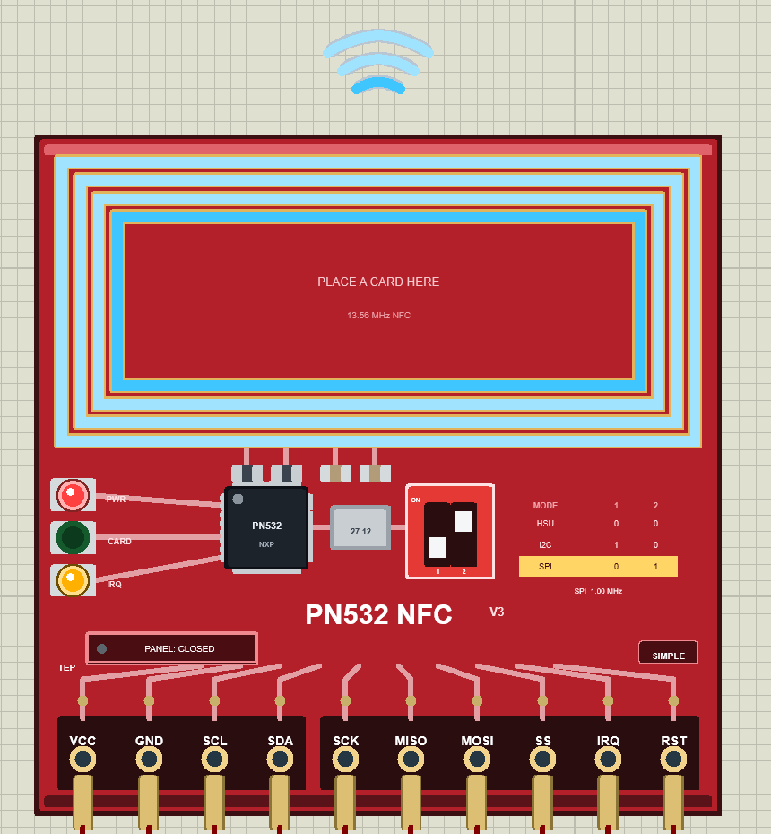
With no card, the coil is cyan: the field stays on, because the sketch keeps searching.
PN532 Advance: The Pop-Up Card Wallet
The Advance device keeps only the board on the schematic. Here is U2 on I2C, with CARD 3 held:
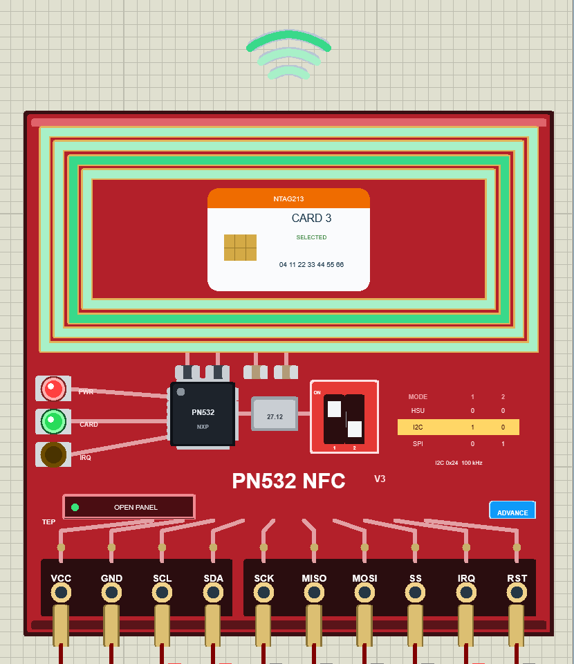
The knobs read 1 0: I2C 0x24 100 kHz. At Run, a pop-up window opens with the look of our TEP Serial Monitor and no Windows title bar: move it by its header, resize it, and reopen it with OPEN PANEL. Its header shows the state and the Cards and Test tabs.
The Cards Page
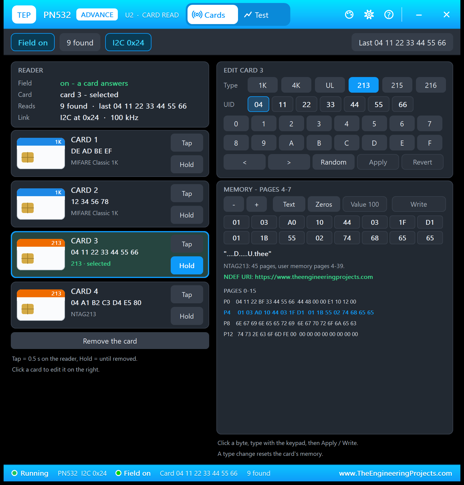
The READER card shows the field ("on - a card answers"), the card ("card 3 - selected"), the reads and the link, "I2C at 0x24 · 100 kHz", measured on your SCL pin. Each card has Tap (0.5 s on the reader) and Hold (until Remove the card).
The Card Editor
Click a card to edit its type (1K, 4K, UL, 213, 215, 216), its UID (hex keypad or Random) and its memory, with the presets Text, Zeros and Value 100. For CARD 3, the editor decodes the NDEF URI in green and lists pages 0-15: the UID with its check bytes BF and 44, the capability container E1 10 12 00 and the NDEF message. Try this: choose 216 for CARD 4, Apply and Hold it, and the sketch prints "Type : NTAG216 (872 bytes)".
The Test Page: Four Measured NFC Test Tools
The four tools on the Test tab only place cards on the reader and read the PN532's own log, never talking to your Arduino, so every number is what your sketch and the card really did, in simulation time. All results below come from U2 (I2C).
1. Read Test: How Fast Does Your Sketch Read a Card?
Choose a card, the tap length and 3, 5 or 10 runs; the tool times each step from the tap. Card 1, five taps of 0.5 s:
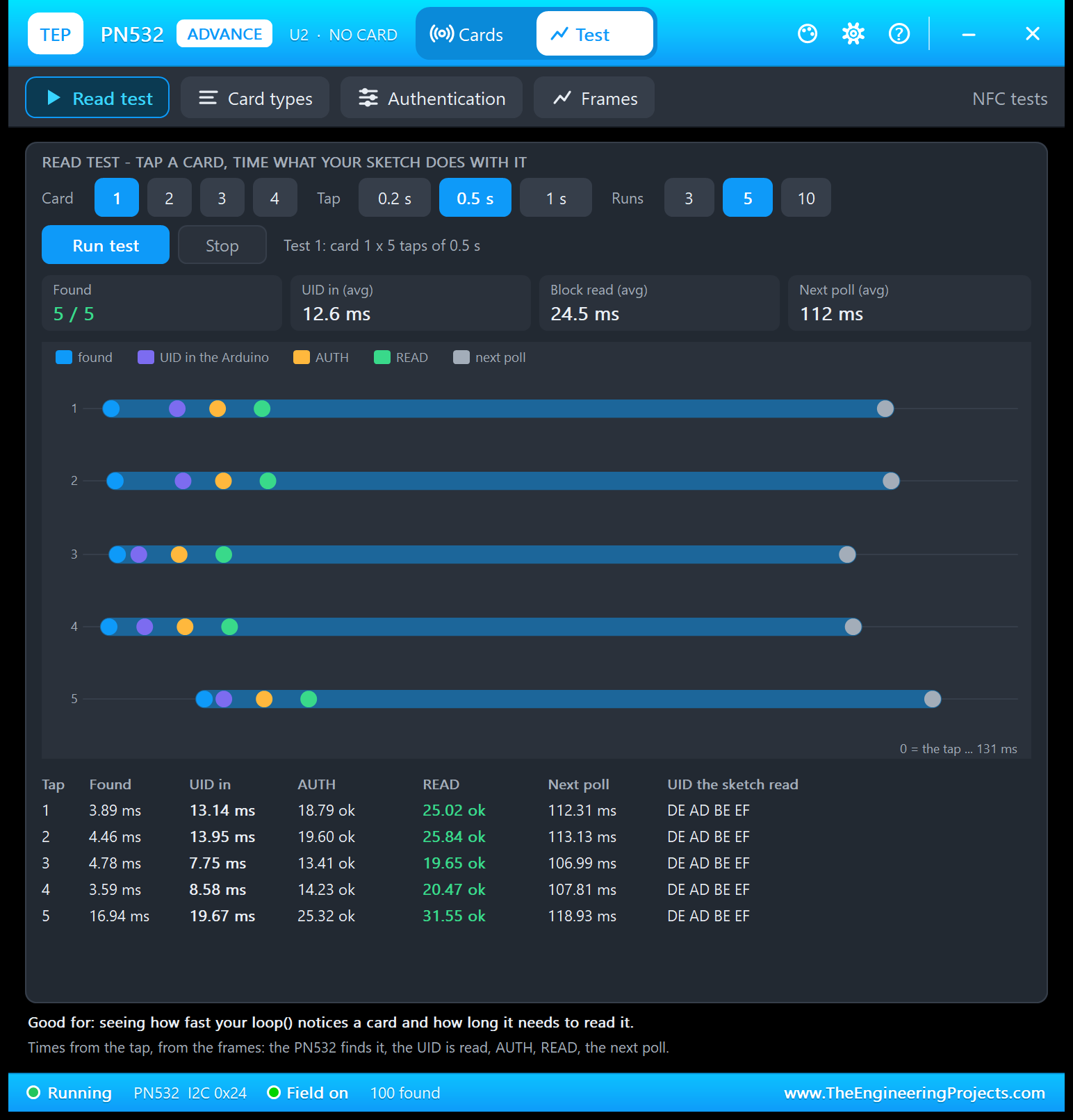
| Tap | Found | UID in | AUTH | READ | Next poll |
|---|---|---|---|---|---|
| 1 | 3.89 ms | 13.14 ms | 18.79 ok | 25.02 ok | 112.31 ms |
| 2 | 4.46 ms | 13.95 ms | 19.60 ok | 25.84 ok | 113.13 ms |
| 3 | 4.78 ms | 7.75 ms | 13.41 ok | 19.65 ok | 106.99 ms |
| 4 | 3.59 ms | 8.58 ms | 14.23 ok | 20.47 ok | 107.81 ms |
| 5 | 16.94 ms | 19.67 ms | 25.32 ok | 31.55 ok | 118.93 ms |
Four taps were found within 4.8 ms: the next 2 ms search try plus 2.8 ms for the card; tap 5 landed while the sketch was not searching. The UID reached the Arduino 2.7 to 9.5 ms later, depending on the library's 10 ms polling. AUTH followed 5.65 ms later and READ 6.2 ms after that: about 2.4 ms card time each, the rest I2C traffic and the library's waits. The next poll came after 112 ms, the time to print at 9600 baud. Good for: seeing how fast your loop() notices and reads a card.
2. Card Types: Does Your Sketch Read Every Card?
This tool holds one test card of each type on the reader for 1 s:
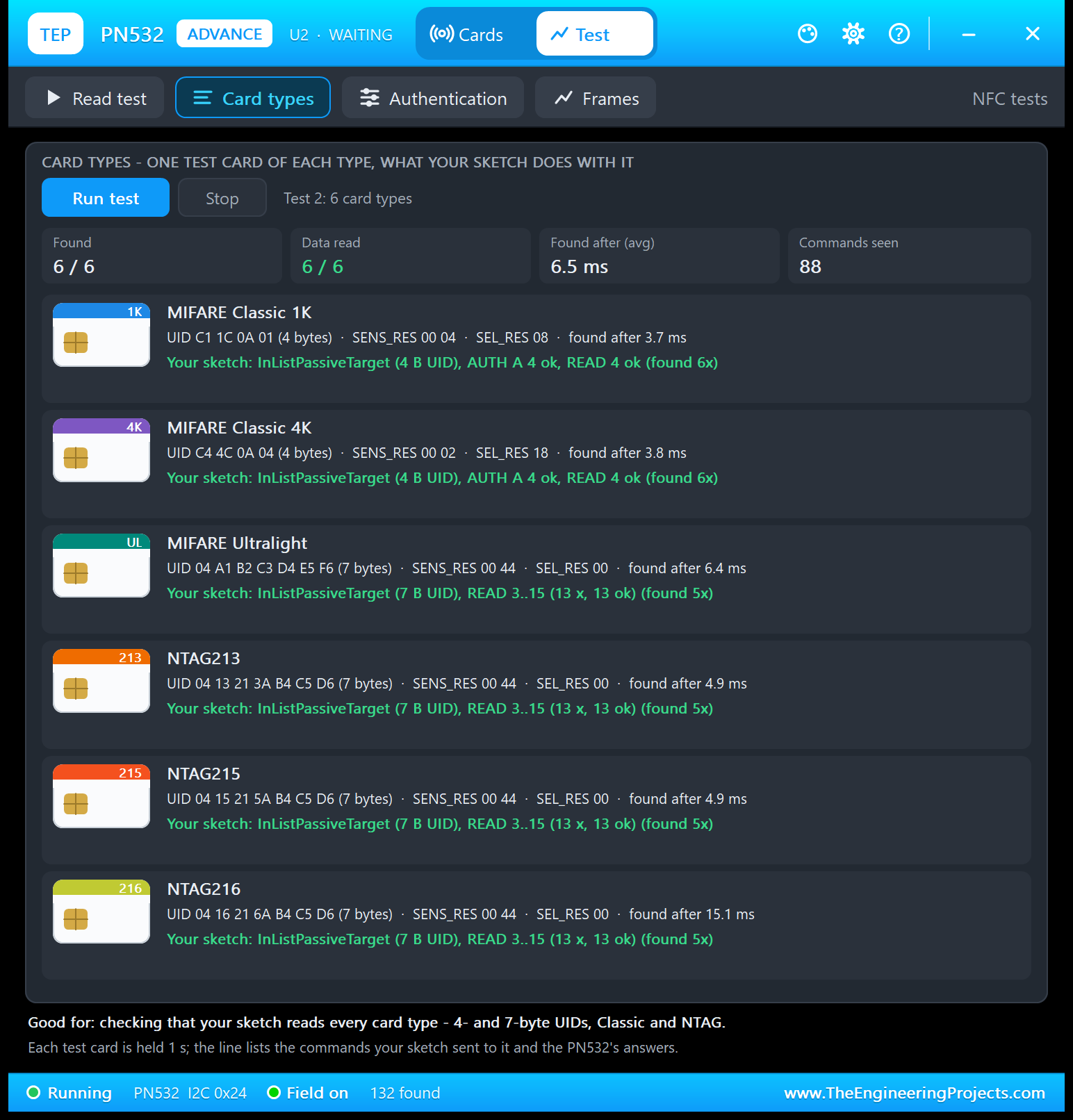
| Card | SENS_RES, SEL_RES, UID | Found after | What the demo sketch did |
|---|---|---|---|
| MIFARE Classic 1K | 00 04, 08, 4 bytes | 3.7 ms | InListPassiveTarget (4 B UID), AUTH A 4 ok, READ 4 ok |
| MIFARE Classic 4K | 00 02, 18, 4 bytes | 3.8 ms | InListPassiveTarget (4 B UID), AUTH A 4 ok, READ 4 ok |
| MIFARE Ultralight | 00 44, 00, 7 bytes | 6.4 ms | InListPassiveTarget (7 B UID), READ 3..15 (13 x, 13 ok) |
| NTAG213 | 00 44, 00, 7 bytes | 4.9 ms | InListPassiveTarget (7 B UID), READ 3..15 (13 x, 13 ok) |
| NTAG215 | 00 44, 00, 7 bytes | 4.9 ms | InListPassiveTarget (7 B UID), READ 3..15 (13 x, 13 ok) |
| NTAG216 | 00 44, 00, 7 bytes | 15.1 ms | InListPassiveTarget (7 B UID), READ 3..15 (13 x, 13 ok) |
SEL_RES 08 or 18 separates the 1K from the 4K, which is how the sketch prints "MIFARE Classic 4K". The 7-byte cards all answer 00, so the sketch reads page 3 and pages 4 to 15: 13 READs. Good for: checking that your sketch reads 4- and 7-byte UIDs, Classic and NTAG.
3. Authentication: Which Key Does Your Sketch Send?
This tool puts a Classic 1K test card (UID A0 7E 51 22) on the reader with Keys as set, Key A changed (A0 A1 A2 A3 A4 A5) or Key B only (access bits 0F 00 FF). Keys as set:
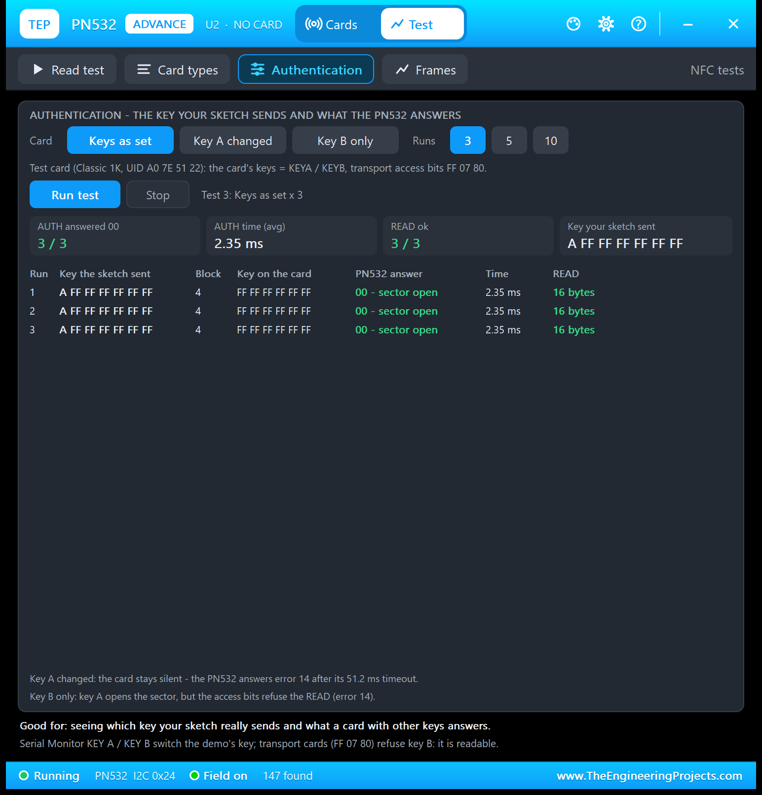
The key the sketch sent, A FF FF FF FF FF FF, opens block 4: 00 - sector open in 2.35 ms, 3 / 3, and every READ got 16 bytes. Now Key A changed:
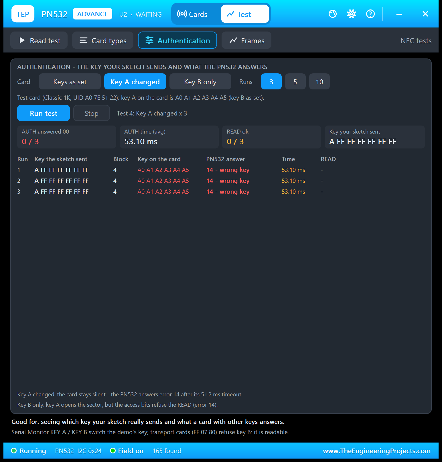
A real MIFARE card never says "wrong key": it stays silent. So the PN532 waits for its 51.2 ms timeout and answers error 14 (authentication error) 53.10 ms after the command; the demo prints "Block 4: authentication failed (key A is not FF..FF)". Key B only (PC-tested) refuses the READ until you type KEY B. Good for: seeing which key your sketch really sends.
4. Frames: The Command / Frame Check
The last tool shows the host link and every frame, here right after the Authentication test:
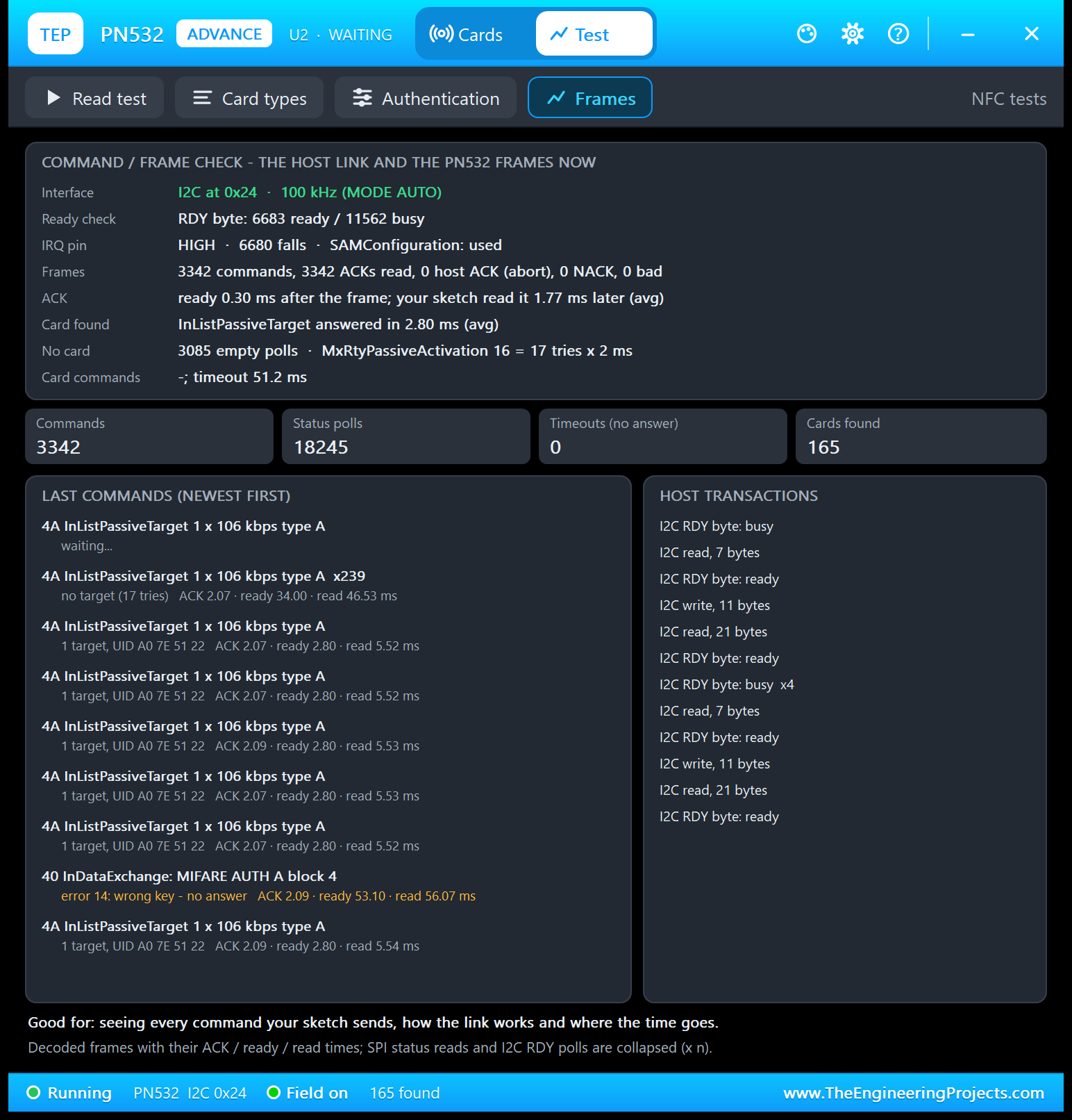
| Line | Reading |
|---|---|
| Interface | I2C at 0x24 · 100 kHz (MODE AUTO) |
| Ready check, IRQ pin | RDY byte: 6683 ready / 11562 busy; 6680 IRQ falls; SAMConfiguration: used (sent by begin()) |
| Frames | 3342 commands, 3342 ACKs read, 0 host ACK (abort), 0 NACK, 0 bad |
| ACK | Ready 0.30 ms after the frame; the sketch read it 1.77 ms later (avg) |
| Card found / no card | InListPassiveTarget answered in 2.80 ms (avg); 3085 empty polls, MxRtyPassiveActivation 16 = 17 tries x 2 ms |
| Card commands | Timeout 51.2 ms |
Read the LAST COMMANDS from the bottom up: InListPassiveTarget finds the test card A0 7E 51 22, 40 InDataExchange: MIFARE AUTH A block 4 gets "error 14: wrong key - no answer" after 53.10 ms, and the sketch finds the card again. In "ACK 2.07 · ready 2.80 · read 5.52 ms", about 2 ms is the I2C read of the answer. The HOST TRANSACTIONS show the bus: "I2C write, 11 bytes" is the InListPassiveTarget frame, "I2C read, 7 bytes" the RDY byte plus the ACK, "I2C read, 21 bytes" the RDY byte plus the answer. Good for: seeing every command your sketch sends and where the time goes.
Settings and Help
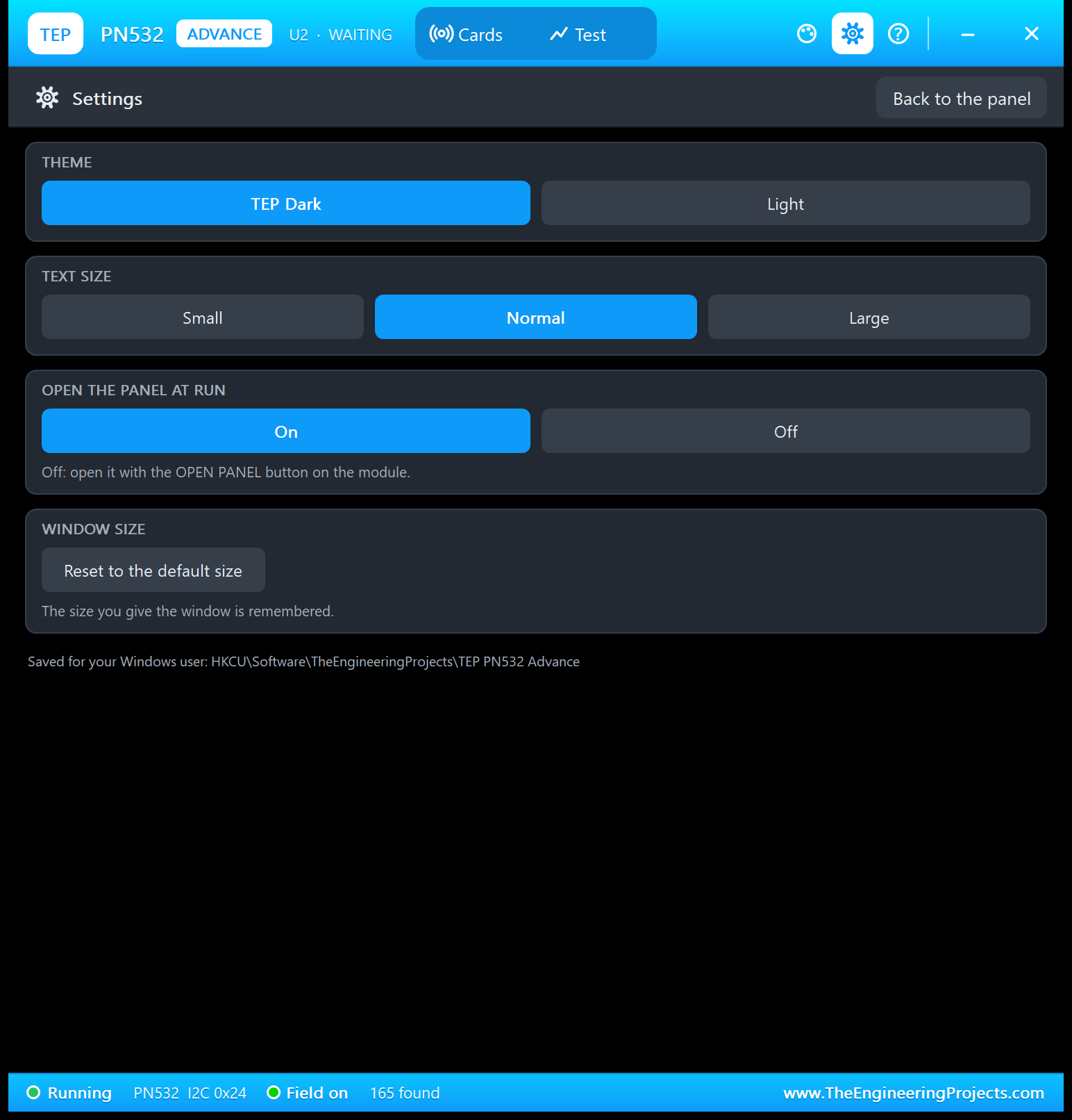
The gear opens Settings: theme (TEP Dark or Light), text size, open the panel at Run and window size.
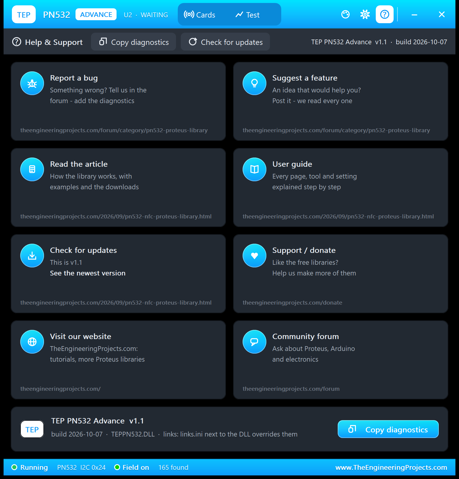
The ? icon opens Help & Support: eight cards with their links (the PN532 forum board, this article, donate, website, forum) and Copy diagnostics for a bug report. A links.ini next to the DLL can change the links.
PN532 Access Control with Arduino in Proteus
Open PN532-ArduinoUnoV3.pdsprj from the Proteus Simulation folder, with the .hex files and the DLLs beside it. It has two Arduino UNOs from our Arduino Library for Proteus V3.0:
- NODE 1 - SPI: UNO 1 (ARD1) with
PN532_SPI_Demo.hex, the PN532 Simple (U1), the access LED D1 on A0 and Serial Monitor U3. - NODE 2 - I2C: UNO 2 (ARD2) with
PN532_I2C_Demo.hex, the PN532 Advance (U2), the access LED D2 on A0 and Serial Monitor U4.
Wiring
| From | To | Why |
|---|---|---|
| PN532 VCC / GND | Supply / ground | Power (both readers) |
| U1 SCK / MISO / MOSI / SS | UNO 1 D13 / D12 / D11 / D10 | SPI: clock, data from and to the PN532, chip select |
| U2 SCL / SDA | UNO 2 A5 / A4 | I2C clock and data, address 0x24 |
| IRQ, RST | Open | Optional (D2 / D3 in the I2C sketch): the library polls the ready status |
| LED + 220 Ω | A0 to GND | The access LED, 3 s on ACCESS GRANTED |
| Serial Monitor RXD / TXD / GND | Arduino D1 / D0 / ground | Shows what the Arduino prints, sends what you type |
D11 - D13 are the UNO's hardware SPI pins and A4 / A5 its I2C pins (see our Introduction to Arduino UNO). In the simulation, VCC goes to the power terminal.
The Arduino Code
Both sketches use the unmodified Adafruit PN532 library (with Adafruit BusIO) and differ only at the top. SPI needs the chip-select pin:
#define PN532_SS 10
#define LED_PIN A0
Adafruit_PN532 nfc(PN532_SS);              // hardware SPI, LSB first, 1 MHz
I2C names the IRQ and reset pins instead; the address 0x24 is fixed:
#define PN532_IRQ   2
#define PN532_RESET 3
#define LED_PIN A0
Adafruit_PN532 nfc(PN532_IRQ, PN532_RESET);  // I2C
In setup(), begin() wakes the chip and sends SAMConfiguration; getFirmwareVersion() is the frame we decoded above:
  nfc.begin();
  uint32_t version = nfc.getFirmwareVersion();
  if (!version) {
    Serial.println(F("PN532 not found - check the wiring and the mode switches"));
    while (true) {}
  }
This line limits a search to 17 tries, so a removed card is noticed:
nfc.setPassiveActivationRetries(0x10); // give up after a few tries, so a removed card is noticedThe loop() searches with InListPassiveTarget:
  uint8_t uid[7], uidLength;
  if (!nfc.readPassiveTargetID(PN532_MIFARE_ISO14443A, uid, &uidLength)) {
    if (lastUidLength) {
      Serial.println(F("Card removed"));
      lastUidLength = 0;
    }
    return;
  }
New in v1.1: the SEL_RES comes from the library's frame buffer, and a pending READ, WRITE, DUMP or NDEF runs on a card that stays:
  lastSak = pn532_packetbuffer[11];
  if (uidLength == lastUidLength && memcmp(uid, lastUid, uidLength) == 0) {   // same card still there
    if (pending) runPending(uid, uidLength);
    delay(200);
    return;
  }
readClassic() names a 4K by its SEL_RES 18, authenticates block 4 and reads it; after a failed AUTH, it selects the card again:
  Serial.println(lastSak == 0x18 ? F("MIFARE Classic 4K") : F("MIFARE Classic 1K"));
  if (!nfc.mifareclassic_AuthenticateBlock(uid, uidLength, 4, useKeyB ? 1 : 0, keyA)) {
    Serial.println(F("Block 4: authentication failed (key A is not FF..FF)"));
    nfc.readPassiveTargetID(PN532_MIFARE_ISO14443A, uid, &uidLength);   // v1.1: the card dropped out - select it again
    return;
  }
  if (!nfc.mifareclassic_ReadDataBlock(4, data)) {
readNtag() first reads the capability container:
  if (nfc.ntag2xx_ReadPage(3, cc)) {          // v1.1: the capability container tells the type
    Serial.print(F("Type   : "));
    Serial.println(cc[2] == 0x12 ? F("NTAG213 (144 bytes)") : cc[2] == 0x3E ? F("NTAG215 (496 bytes)") : cc[2] == 0x6D ? F("NTAG216 (872 bytes)") :
                   cc[2] == 0x06 ? F("MIFARE Ultralight (48 bytes)") : F("unknown"));
  }
Then it reads pages 4 to 15 and walks the TLV blocks to the URI record:
    if (type == 0x03) {                                   // NDEF message
      if (length == 0) { Serial.println(F("NDEF: empty message")); return; }
      uint8_t *record = data + i + 2;
      if (record[1] == 1 && record[3] == 'U') {           // short record, type "U" (URI)
        static const char *prefixes[] = {"", "http://www.", "https://www.", "http://", "https://"};
The access decision uses the UID only; the list starts with CARD 1 and CARD 3 and holds up to 8 UIDs:
struct AllowedUid { byte size; byte uid[7]; };
AllowedUid allowed[MAX_ALLOWED] = { {4, {0xDE, 0xAD, 0xBE, 0xEF}}, {7, {0x04, 0x11, 0x22, 0x33, 0x44, 0x55, 0x66}} };
A UID on the list lights the LED for 3 s:
  if (findAllowed(uid, uidLength) >= 0) {
    Serial.println(F("-> ACCESS GRANTED"));
    digitalWrite(LED_PIN, HIGH); ledOn = true; ledOffAt = millis() + LED_MS;
  } else Serial.println(F("-> ACCESS DENIED"));
ADD and DEL change the list in the UNO's RAM, so a reset restores it. To change a sketch, see How to get the HEX file from Arduino; new to Arduino? Read our Arduino Tutorial for Beginners.
Serial Monitor Commands
| Command | What it does |
|---|---|
| HELP | The command list |
| STATUS | Cards read, allowed UIDs, key, LED, PN532 firmware and the link |
| ADD [uid] | Allows the last card read, or a UID in hex (8 or 14 digits, spaces allowed) |
| DEL [uid] | Removes it from the list |
| READ n | The card on the reader: block n (Classic, with the key) or pages n to n+3 (NTAG / Ultralight) |
| WRITE n text | 16 characters into block n (not block 0, not a trailer) or into pages n to n+3 (n from 4) |
| DUMP | The card on the reader: Classic sectors 0-15 or the NTAG pages |
| NDEF url | The NTAG / Ultralight card on the reader gets that URI record |
| KEY A / KEY B | The key type (FF FF FF FF FF FF) that opens the Classic sectors |
How to Run the Demo
- Press Run. Both Serial Monitors (9600 baud) and U2's pop-up open, and the antennas turn cyan.
- On U1's panel, click CARD 1 and CARD 3 (granted, D1 lights), then CARD 2 and CARD 4 (denied).
- Type ADD on U3, read CARD 2 again (granted), click REMOVE CARD and type STATUS.
- In U2's pop-up, Hold CARD 3 and watch U4, then edit the cards and run the four tools.
PN532 Proteus Simulation Results
The Serial Monitor in Its Simple Interface
Both monitors in this demo run in the Simple interface of our TEP Serial Monitor, as in every monitor screenshot here. Only the log, the send box and one slim toolbar row stay visible (baud rate, follow, pause, search and clear); the header, the quick buttons and the status bar are hidden, so the window stays small.
- Switch to it: right-click the log and choose Simple interface, or press Ctrl+Shift+U.
- Back to the full view: click the corner button (the expand arrows at the top right), press Esc or Ctrl+Shift+U, or right-click and choose Full interface.
- Your choice is remembered.
Type commands such as STATUS or ADD in the send box and press Enter; the quick buttons (STATUS, ADD, DEL, DUMP) come back with the full view. RXD2, the monitor's second input, is not used: SPI and I2C have no serial line to watch. Read all about the monitor in TEP Serial Monitor Advance for Proteus.
Start-Up and CARD 1 on SPI
After Run, each monitor prints its banner. Here is U3 after CARD 1:
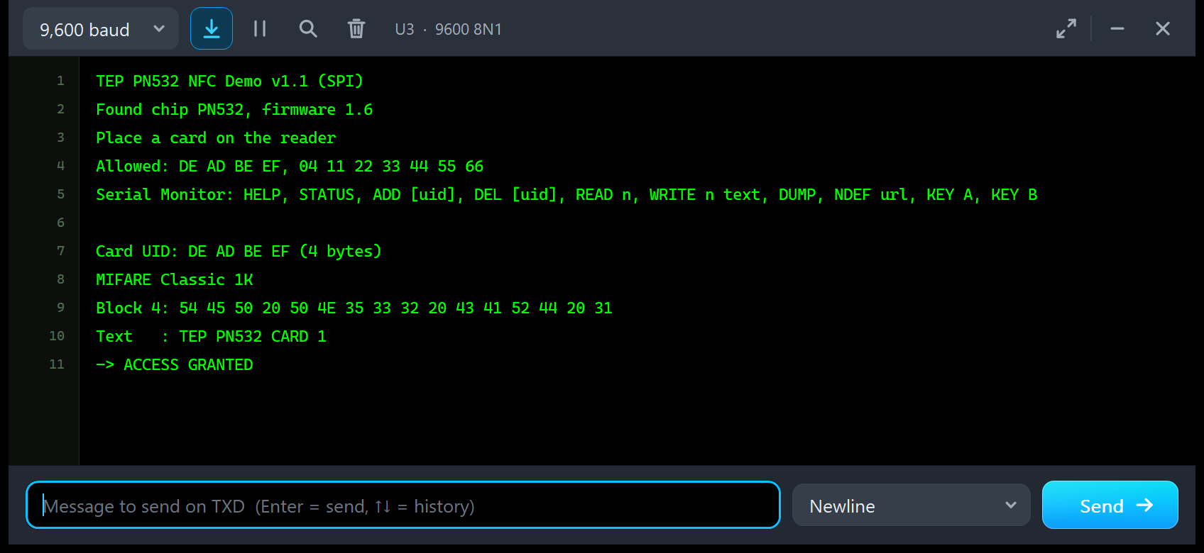
TEP PN532 NFC Demo v1.1 (SPI)
Found chip PN532, firmware 1.6
Place a card on the reader
Allowed: DE AD BE EF, 04 11 22 33 44 55 66
Serial Monitor: HELP, STATUS, ADD [uid], DEL [uid], READ n, WRITE n text, DUMP, NDEF url, KEY A, KEY B

Card UID: DE AD BE EF (4 bytes)
MIFARE Classic 1K
Block 4: 54 45 50 20 50 4E 35 33 32 20 43 41 52 44 20 31
Text   : TEP PN532 CARD 1
-> ACCESS GRANTED
"Found chip PN532, firmware 1.6" proves that SPI works. In block 4, 54 45 50 is "TEP" in ASCII, and DE AD BE EF is on the allowed list: ACCESS GRANTED, and D1 lights for 3 s.
ADD, Card Removed and STATUS
Now the best part of the new sketch. After CARD 3, I clicked CARD 2 (denied) and typed ADD: "Added 12 34 56 78 (3 allowed)". Then came CARD 4, CARD 2 again, REMOVE CARD and STATUS. Lines you send carry a blue TX tag, the Arduino's lines a green RX tag:
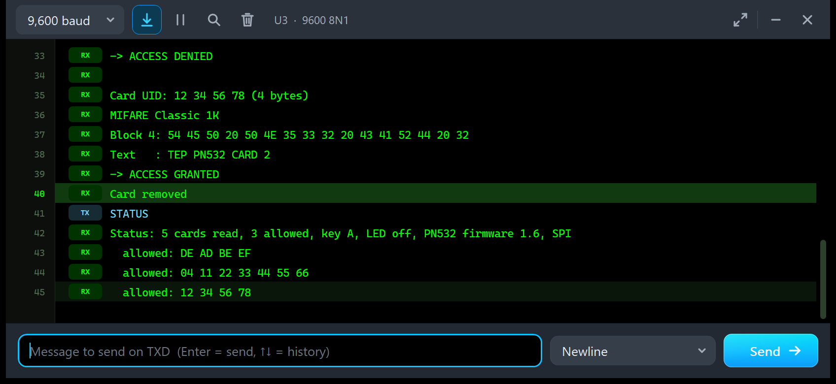
-> ACCESS DENIED

Card UID: 12 34 56 78 (4 bytes)
MIFARE Classic 1K
Block 4: 54 45 50 20 50 4E 35 33 32 20 43 41 52 44 20 32
Text   : TEP PN532 CARD 2
-> ACCESS GRANTED
Card removed
STATUS
Status: 5 cards read, 3 allowed, key A, LED off, PN532 firmware 1.6, SPI
  allowed: DE AD BE EF
  allowed: 04 11 22 33 44 55 66
  allowed: 12 34 56 78
The first line ends CARD 4's report, and CARD 2 is now granted. STATUS sums up the session: 5 cards read, 3 allowed, key A, firmware 1.6 over SPI. In v1.0, allowing a card meant building a new HEX file.
An NTAG213 over I2C
On U2, I held CARD 3 on the pop-up. After the I2C banner, U4 prints:
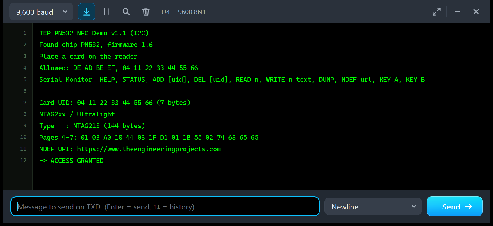
Card UID: 04 11 22 33 44 55 66 (7 bytes)
NTAG2xx / Ultralight
Type   : NTAG213 (144 bytes)
Pages 4-7: 01 03 A0 10 44 03 1F D1 01 1B 55 02 74 68 65 65
NDEF URI: https://www.theengineeringprojects.com
-> ACCESS GRANTED
These are the bytes we decoded in the NDEF section. The interface changes the wires and the speed, not the result.
Troubleshooting
- "PN532 not found - check the wiring and the mode switches": check VCC / GND (the PWR LED must be lit), the SPI or I2C wires and the MODE property.
- No card is detected: click a card while the simulation runs; a running test tool owns the field.
- Each loop() without a card takes about 40 ms: correct, 17 tries at 2 ms.
- "Block 4: authentication failed (key A is not FF..FF)": wrong key; the Authentication tool shows both keys.
- "Block 4: read failed" with KEY B: a transport card refuses its readable key B.
- No panel, pop-up or monitor: a DLL is missing; click OPEN PANEL or OPEN MONITOR.
- The board looks like v1.0: replace the LIB, delete TEPPN532.IDX and re-pick the part.
- SoftwareSerial for HSU: Proteus 8.5 cannot receive with it; use SPI, I2C or a Mega's Serial1.
Things to Know Before Using a Real PN532 Module
The demo sketches use only the Adafruit PN532 library, so they run on real UNOs and V3 boards, too. Keep in mind:
- Supply: VCC 3.3 V or 5 V; the V3 board has its own 3.3 V regulator.
- Logic levels: the V3 board has a level shifter for I2C and HSU (5 V TTL), but SPI is 3.3 V TTL: from a 5 V UNO, use a level shifter (or 1 k / 2 k dividers on SCK, MOSI and SS). MISO (3.3 V) is read correctly by the UNO.
- Set the mode switch before power-up: HSU = 1 OFF, 2 OFF; I2C = 1 ON, 2 OFF; SPI = 1 OFF, 2 ON. The PN532 reads it at reset.
- I2C pull-ups: an I2C bus needs pull-up resistors on SDA and SCL; check whether your board already carries them.
- Range: 5 - 7 cm with the board's PCB antenna (Elechouse data); metal near the antenna detunes it.
- HSU: use a Mega's Serial1. The Adafruit library 1.3.4 reads a fixed number of bytes on HSU, so some calls wait for its 1 s timeout; our model reproduces this.
- Security: a UID is not a secret, and MIFARE Classic's Crypto1 is weak: a UID list is fine for learning, not for a real door.
Limitations of the Simulation
- Not modelled: NFC-DEP / ISO-DEP (ISO 14443-4) targets, card emulation, FeliCa, type B and Jewel cards, several cards at once, Crypto1 on the air (keys are compared directly), the SAM, the RF level and distance, NTAG counters and signature, card tearing.
- The model is our own implementation, written from NXP's published PN532 user manual and data sheet, the MIFARE Classic, Ultralight and NTAG21x data sheets and ISO/IEC 14443-3; it contains no NXP firmware or code. Its times are model values, so measure a real project on hardware.
- Tested in Proteus 8.5 SP0 on 7 Oct 2026 (the demo, both panels, the four tools, every screenshot here) and with 1,781 automatic PC checks, all passed, 116 of them with the unmodified Adafruit PN532 library over SPI, I2C and HSU and 116 with the real v1.1 sketches. HSU, a v1.0 design after the update and Key B only were tested on the PC only; the image marked "PC render" was drawn by the model's own code. Proteus 7 is not supported.
Need a cheaper 13.56 MHz reader? See our MFRC522 RFID Library for Proteus; for 125 kHz tags, our EM18 RFID Library for Proteus. To send a UID to another Arduino, add our nRF24L01 Library for Proteus or CC1101 Library for Proteus.
So, that was all about the PN532 NFC Library for Proteus V1.1. I hope the card panel, the card editor and the four test tools make NFC much easier to understand, so your access-control or NFC-tag project works the first time you wire a real PN532. If you use the PN532 NFC Library for Proteus in a project, please share your feedback in the comments or in our forum, and if you have any questions, ask in the comments and I will help you out. Till the next tutorial, take care and have fun!