Hello friends, I hope you all are doing great. Today, I am going to share the new ESP-01 Wi-Fi Library for Proteus V1.1. The ESP-01 is the tiny black ESP8266 board that gives an Arduino Wi-Fi: with a handful of AT commands, your sketch can join a router, serve a web page to a phone, or upload sensor readings to the cloud. With this ESP-01 Library for Proteus, you can build and debug those IoT projects on your PC, without a 3.3 V supply, a router or an internet account.
In this new version, you get two devices in one library: ESP-01 Simple, which draws a virtual smartphone on the schematic, and ESP-01 Advance, which opens a pop-up window with the phone and four real Wi-Fi test tools (Wi-Fi join, web request, cloud upload and AT check). I am also sharing a complete Arduino ESP8266 Proteus simulation: one UNO runs a web server that switches an LED from the phone's browser, and the other uploads a potentiometer reading to a cloud service every 20 seconds.
NOTICE: This library is one of our biggest so far. Our ESP-01 model runs the AT firmware behaviour of the real module: the boot text, the UART speeds, Wi-Fi joins with DHCP, a TCP web server, a virtual internet host with a cloud API, and a virtual router that every ESP-01 in your design shares. It took our team a lot of hard work, many test runs and many design changes, and this library is a tribute to that effort. Your feedback is the fuel that keeps us going, so please tell us what you think in the comments below or in the ESP-01 Library board of our forum. And if our free libraries help you in your studies or work, you can buy us a coffee (our donation page is coming soon). So, let's get started with the ESP-01 Library for Proteus:
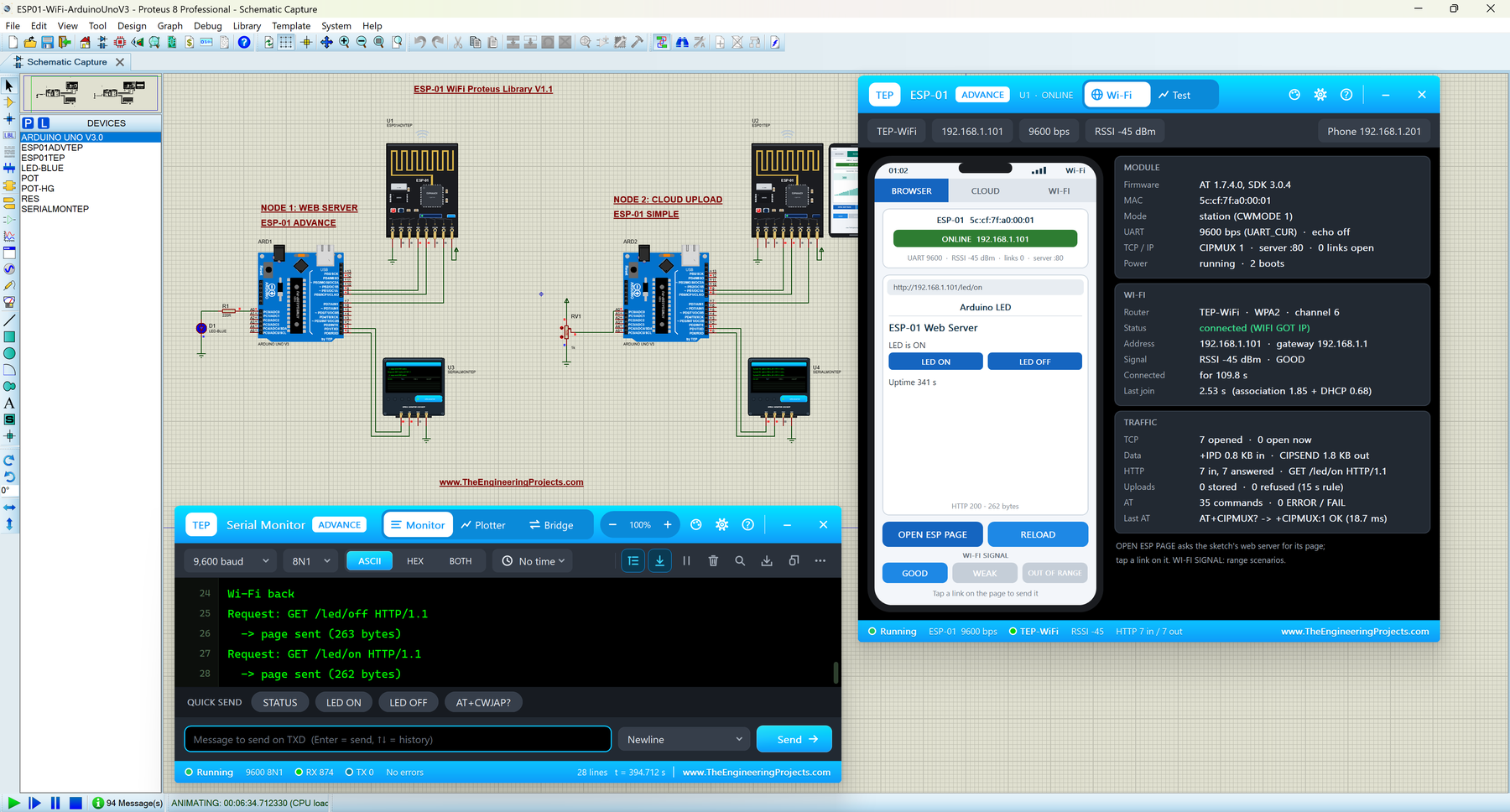
What is the ESP-01 Wi-Fi Module?
The ESP-01 is the smallest board built around Espressif's ESP8266EX Wi-Fi chip. It has the chip, 1 MB of flash, a PCB antenna (the gold meander line), a red power LED, a blue LED on its TX line and a 2 x 4 pin header. It ships with Espressif's AT firmware, so an Arduino controls it over a UART (the two-wire TX / RX serial port) with text commands that start with "AT", like AT+CWJAP (join a Wi-Fi network) or AT+CIPSEND (send data over TCP).
With an ESP-01, an Arduino can:
- join a Wi-Fi router and get an IP address,
- run a small web server that a phone or PC opens in its browser,
- send sensor readings to cloud services such as IoT dashboards,
- talk to other ESP-01 modules over TCP or UDP.
Wi-Fi and Network Terms You Will See
| Term | Meaning |
|---|---|
| SSID | The name of a Wi-Fi network, for example TEP-WiFi |
| Association | The module and the router agree to talk: the firmware prints WIFI CONNECTED |
| DHCP | The router gives the module an IP address: the firmware prints WIFI GOT IP |
| RSSI | Received signal strength in dBm; -45 dBm is strong, -80 dBm is weak |
| TCP | A reliable connection between two devices, used by web pages and HTTP |
| +IPD | The line the module prints when data arrives: +IPD,<link>,<length>:<data> |
| CIPMUX | Single (0) or multiple (1) connections; a web server needs CIPMUX=1 |
| HTTP GET | A browser's request for a page, for example GET /led/on HTTP/1.1 |
What's New in ESP-01 Library for Proteus V1.1
- Two devices: ESP-01 Simple (
ESP01TEP, phone on the sheet) and ESP-01 Advance (ESP01ADVTEP, pop-up window), on one model (TEPESP01.DLL). - Close and reopen the Simple phone: a red X in its status bar, a PANEL button on the board.
- Board: the PCB antenna glows orange while the module sends and green while it receives, plus a SIMPLE / ADVANCE badge. The red PWR and blue TX LEDs keep their real behaviour.
- Four Wi-Fi test tools in the Advance pop-up: Wi-Fi join, Web request, Cloud upload and AT check.
- A more realistic model: a join now takes 1.4 - 2.0 s for the association plus 0.6 - 1.2 s for DHCP (it was always 2.8 s), the internet host answers after 40 - 90 ms, and settings saved in the module's flash no longer leak into the next simulation run.
- TEP Serial Monitor in the demo instead of the Virtual Terminal, and smarter sketches that take commands from the monitor and set the module up again after a reset.
- Lighter package: about 1.6 MB, without the C++ source code.
ESP-01 Library for Proteus: Simple vs Advance
Both devices run the same Wi-Fi model; only the panel differs:
| Feature | Simple | Advance |
|---|---|---|
| Full ESP-01 model (AT firmware, Wi-Fi, TCP / UDP, web server, internet host) | ✔ | ✔ |
| PWR and TX LEDs, glowing PCB antenna, animated waves | ✔ | ✔ |
| Virtual phone drawn on the schematic | ✔ | ✘ |
| Phone in a pop-up window you can move, resize and minimise | ✘ | ✔ |
| MODULE, WI-FI and TRAFFIC cards | ✘ | ✔ |
| Wi-Fi join test (re-join, router drop, module reset) | ✘ | ✔ |
| Web request test and cloud upload check | ✘ | ✔ |
| AT check with response times | ✘ | ✔ |
| TEP Dark / Light theme, text size, Help page with Copy diagnostics | ✘ | ✔ |
| Same device name as v1.0 (old designs keep working) | ✔ | ✘ |
Pick Simple when you want the phone on the sheet beside your circuit, and Advance when the sheet is crowded or you want to test and debug your Wi-Fi code. The demo uses both.
Download ESP-01 Library for Proteus
Click the button below to download ESP-01-WiFi-Library-for-Proteus-v1.1.zip:
ESP-01 Wi-Fi Library for Proteus V1.1- README.txt: a detailed guide to the files.
- Proteus Library Files:
TEPESP01.LIB(both devices),TEPSERIALMON.LIBand our Arduino UNO libraryArduinoV3TEP.LIB/ArduinoV3TEP.IDX. - Proteus Model Files:
TEPESP01.DLLandTEPSERIALMON.DLL. - Proteus Simulation: the demo project, two .hex files and copies of both DLLs.
- Arduino Code: the two demo sketches and AltSoftSerial 1.4 (MIT licence). SoftwareSerial comes with the Arduino IDE.
If you don't have Proteus yet, read How to Download and Install Proteus 7 and 8. New to libraries? Follow How to Install a New Library in Proteus.
How to Install ESP-01 Library for Proteus
- Close Proteus and extract the whole zip file.
- Copy the four files from Proteus Library Files into the LIBRARY folder, usually
C:\Program Files (x86)\Labcenter Electronics\Proteus 8 Professional\LIBRARY(on some PCsC:\ProgramData\Labcenter Electronics\Proteus 8 Professional\LIBRARY). - Copy
TEPESP01.DLLandTEPSERIALMON.DLLinto the MODELS folder. - Start Proteus, press P and search for ESP. You get the Simple and the Advance device (category Peripherals > Wireless).
Updating from v1.0? Replace TEPESP01.LIB and TEPESP01.DLL, and delete any TEPESP01.IDX from the LIBRARY folder, or the parts list keeps showing the old device. The library was tested in Proteus 8.5; Proteus 7 is not supported.
ESP-01 Module in Proteus
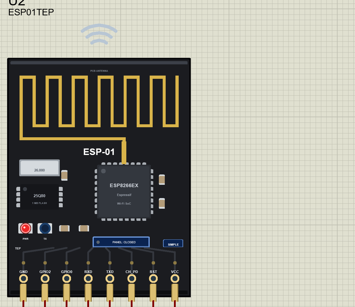
We designed the module as a clean TEP board in the black of the real ESP-01: the gold PCB antenna, the ESP8266EX chip, the 26 MHz crystal, the 25Q80 flash chip, the red PWR and blue TX LEDs and the 2 x 4 header. Here is the ESP-01 Advance on the schematic with its pop-up window closed:
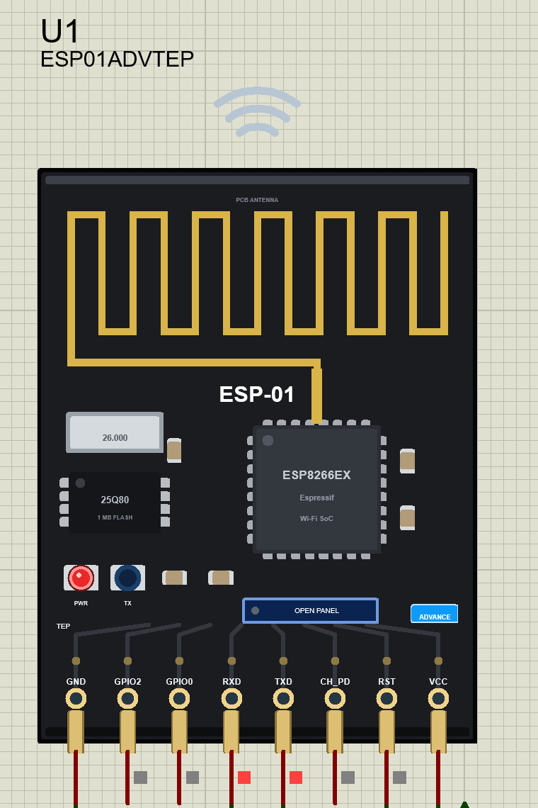
Pinout
The pins are in the real header order (pins 1 - 8):
| Pin | Function | Demo connection |
|---|---|---|
| GND | Ground | GND |
| GPIO2 | General purpose pin (pulled up) | Open |
| GPIO0 | LOW at reset = flash download mode | Open |
| RXD | Serial input: AT commands from the Arduino | Arduino D9 |
| TXD | Serial output: answers and +IPD data | Arduino D8 |
| CH_PD | Chip enable (EN): must be HIGH | Open (the model pulls it up) |
| RST | Reset input: LOW = reset | Arduino D7 |
| VCC | 3.3 V supply | 3.3 V |
LEDs, Antenna and Waves
| Indicator | What it shows |
|---|---|
| PWR LED (red) | On while VCC and GND are powered |
| TX LED (blue) | Flickers with TXD while the module talks to the Arduino, like on the real board |
| PCB antenna | Orange while the module transmits, green while it receives, gold when idle |
| Waves above the antenna | Ripple out while sending, in while receiving |
The board button is PANEL on the Simple (green dot SHOWN, grey dot CLOSED) and OPEN PANEL on the Advance.
Component Properties
Double-click the module to open Edit Properties. The properties are the same on Simple and Advance:
| Property | Meaning | Default |
|---|---|---|
| WIFISSID | Router name (SSID) in range | TEP-WiFi |
| WIFIPASS | Router password | 12345678 |
| BAUD | Factory UART speed | 115200 |
| PANEL | Phone tab at start: BROWSER, CLOUD or WIFI | BROWSER |
| PAGEPORT | Port the phone opens | 80 |
| CLOCK | Clock: PC or a fixed YYYY-MM-DD HH:MM:SS | PC |
Every ESP-01 in a design joins the same virtual router and gets the address 192.168.1.1xx, where xx is its component number (U1 gets 192.168.1.101, U2 gets 192.168.1.102).
The Virtual Phone: ESP-01 Simple
Beside the Simple module, we have drawn a smartphone with three tabs: BROWSER, CLOUD and WI-FI. In the demo, U2 runs the cloud uploader, so its phone starts on the CLOUD tab:
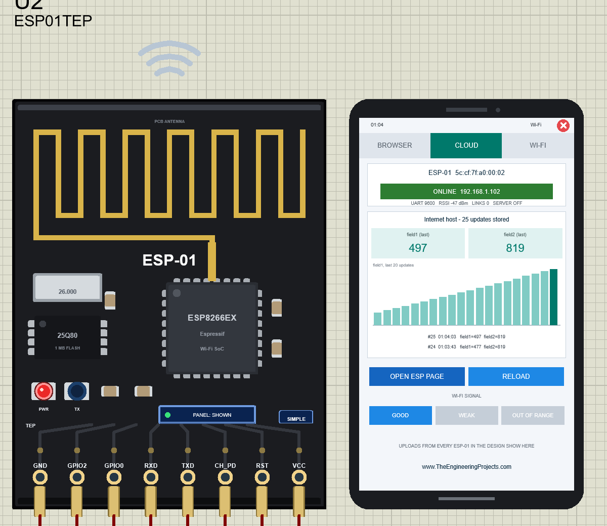
The status card says ONLINE 192.168.1.102. Below it, the internet host shows "25 updates stored", the last field1 (497, the uptime in seconds) and field2 (819, the potentiometer on A0), and a bar chart of the last 20 field1 values. Turn the potentiometer, and field2 follows on the next upload.
Every Control on the Phone
| Part | What it does |
|---|---|
| Status card | MAC address and state: BOOTING, CONNECTING, GETTING AN IP ADDRESS, ONLINE address, OUT OF RANGE, WRONG WI-FI PASSWORD ... plus UART speed, RSSI, open links and the server port |
| BROWSER | The page the Arduino serves: title, text and links (tap them); the address bar and the HTTP status |
| CLOUD | The internet host: updates stored, last field1 / field2, a bar chart, the last two entries |
| WI-FI | The router (name, WPA2, channel 6, gateway 192.168.1.1) and its DHCP clients |
| OPEN ESP PAGE / RELOAD | Opens http://<module address>/ or loads the last page again |
| WI-FI SIGNAL | GOOD, WEAK or OUT OF RANGE |
| Red X | Closes the phone |
The WI-FI Tab
The WI-FI tab shows the virtual router and everyone it gave an address to: both ESP-01 modules and both phones, with their signal levels. This is a nice way to explain DHCP to students:
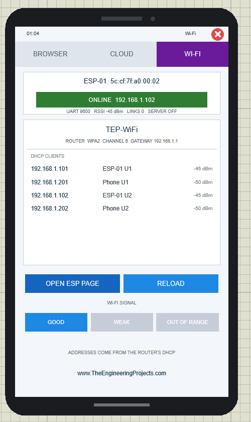
When There is No Web Server
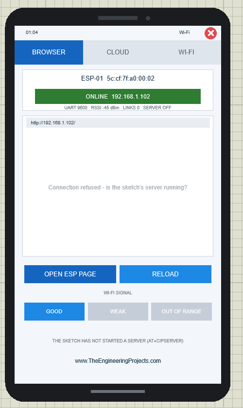
Open the BROWSER tab on U2 and tap OPEN ESP PAGE. U2's sketch is the uploader, not a server, so the phone says "Connection refused - is the sketch's server running?" and the hint below says the sketch has not started a server (AT+CIPSERVER). That is exactly what a real browser shows:
Closing and Opening the Phone
Click the red X in the phone's status bar. Only the board stays, and its button says PANEL: CLOSED with a grey dot. Click PANEL to bring the phone back; the module keeps working while the phone is closed.
ESP-01 Advance: The Pop-Up Panel
The Advance device keeps only the board on the schematic. At Run, a TEP pop-up window opens with the look of our TEP Serial Monitor. Move it by its header, resize or minimise it, and reopen it with OPEN PANEL after you close it. The header shows the part and its state (U1 · ONLINE), the tabs Wi-Fi and Test, and the theme, Settings and Help icons. The toolbar chips show the network, the IP address, the UART speed, the RSSI and the phone's address.
The Wi-Fi Page
In the demo, U1 runs the web server. Tap OPEN ESP PAGE, and the phone shows the Arduino's page "ESP-01 Web Server" with LED ON and LED OFF links. Tap LED ON: the browser requests /led/on, the sketch switches LED D1 on and sends the new page:
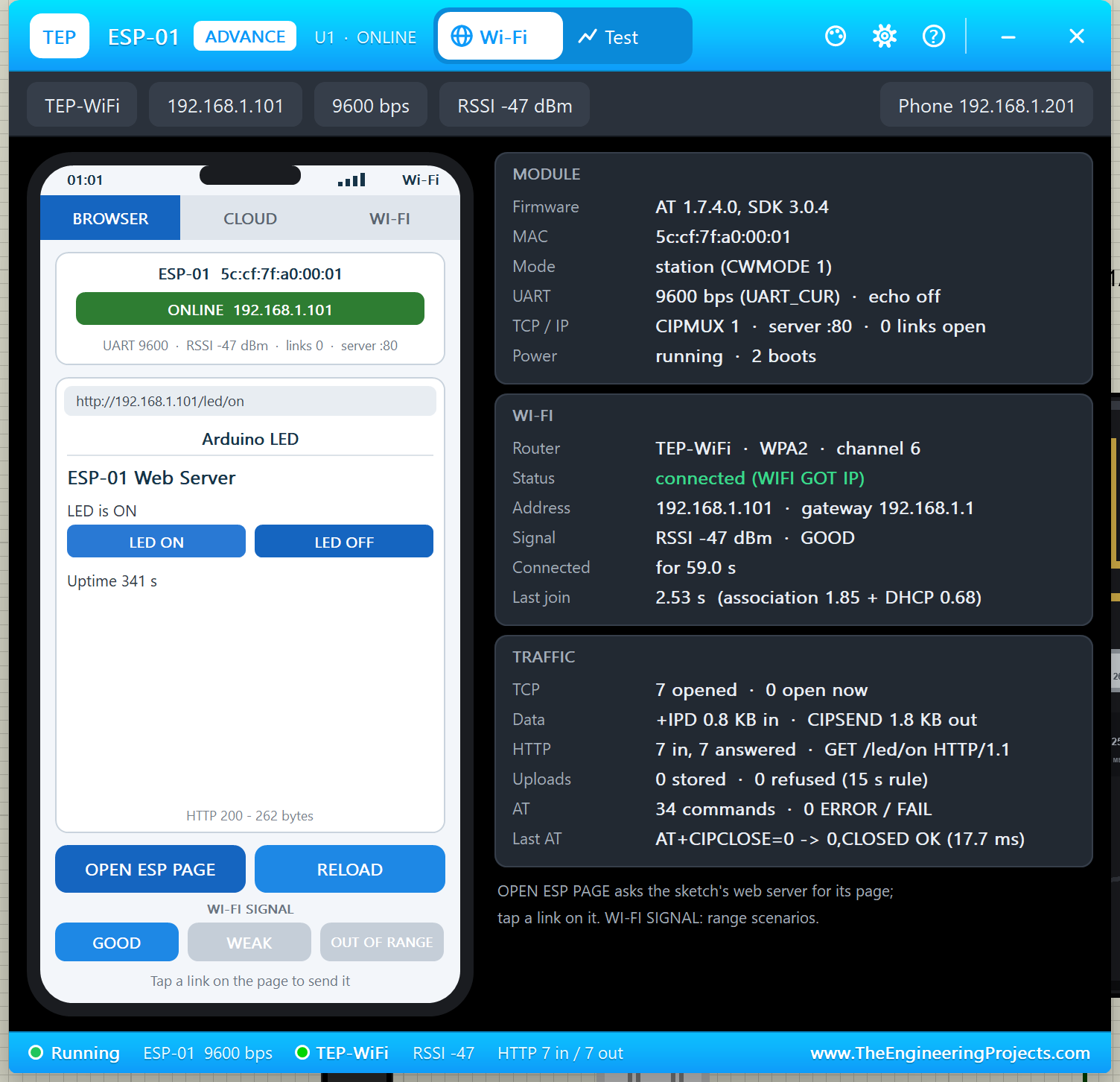
- MODULE: firmware AT 1.7.4.0, SDK 3.0.4; MAC 5c:cf:7f:a0:00:01; station (CWMODE 1); 9600 bps (UART_CUR), echo off; CIPMUX 1, server :80; running, 2 boots.
- WI-FI: TEP-WiFi, WPA2, channel 6; connected (WIFI GOT IP); 192.168.1.101, gateway 192.168.1.1; RSSI -45 dBm GOOD; last join 2.53 s (association 1.85 + DHCP 0.68).
- TRAFFIC: 7 TCP connections, +IPD 0.8 KB in, CIPSEND 1.8 KB out, 7 HTTP requests and 7 answered, 34 AT commands with 0 ERROR, and the last AT exchange with its response time.
Click OUT OF RANGE, and the module loses the router: the card turns red and the sketch prints "Wi-Fi lost - the ESP-01 reconnects by itself". Click GOOD, and the firmware re-joins: "Wi-Fi back".
The Test Page: Wi-Fi Test Tools
The Test page is what makes the Advance device special. It has four tools, and every number on it is measured on the running model, with your real sketch answering.
1. Wi-Fi Join: How Long Until the Module is Online?
Choose Re-join, Router drop or Module reset, then 3, 5 or 10 runs. Each bar is split into the association (WIFI CONNECTED) and the DHCP part (WIFI GOT IP). Here is the router dropping out for 3 s, three times:
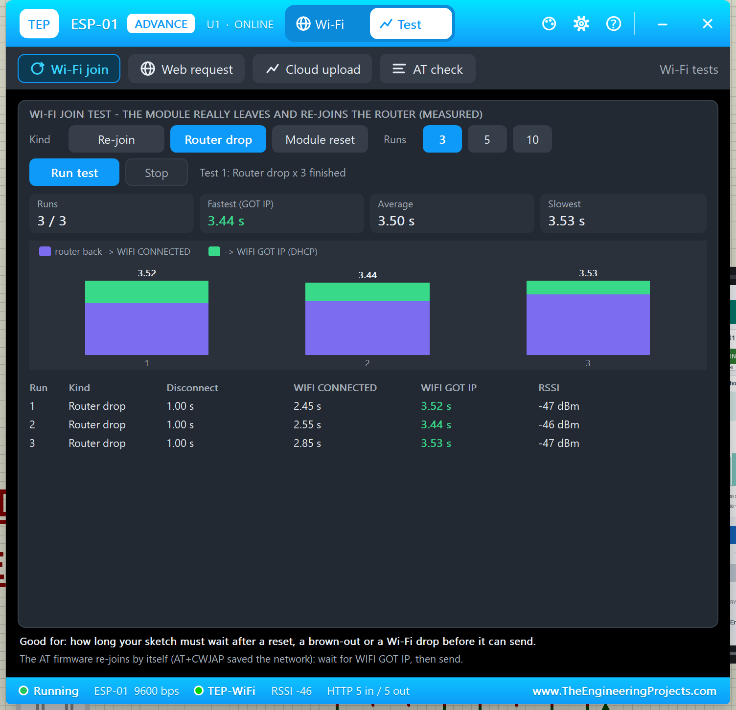
In every run, the firmware noticed the lost router after 1.00 s (WIFI DISCONNECT) and re-joined by itself when it came back: WIFI CONNECTED after 2.45 - 2.85 s and WIFI GOT IP after 3.44 - 3.53 s. A simple Re-join took 2.44 / 2.53 / 2.86 s in my run.
Module reset is the most interesting one. It resets the module like a RST pulse or a brown-out: "ready" after 0.30 s, then the firmware's auto-connect. But the module is back at 115200 bps without its web server, so the sketch must notice. Watch U3 on the right:
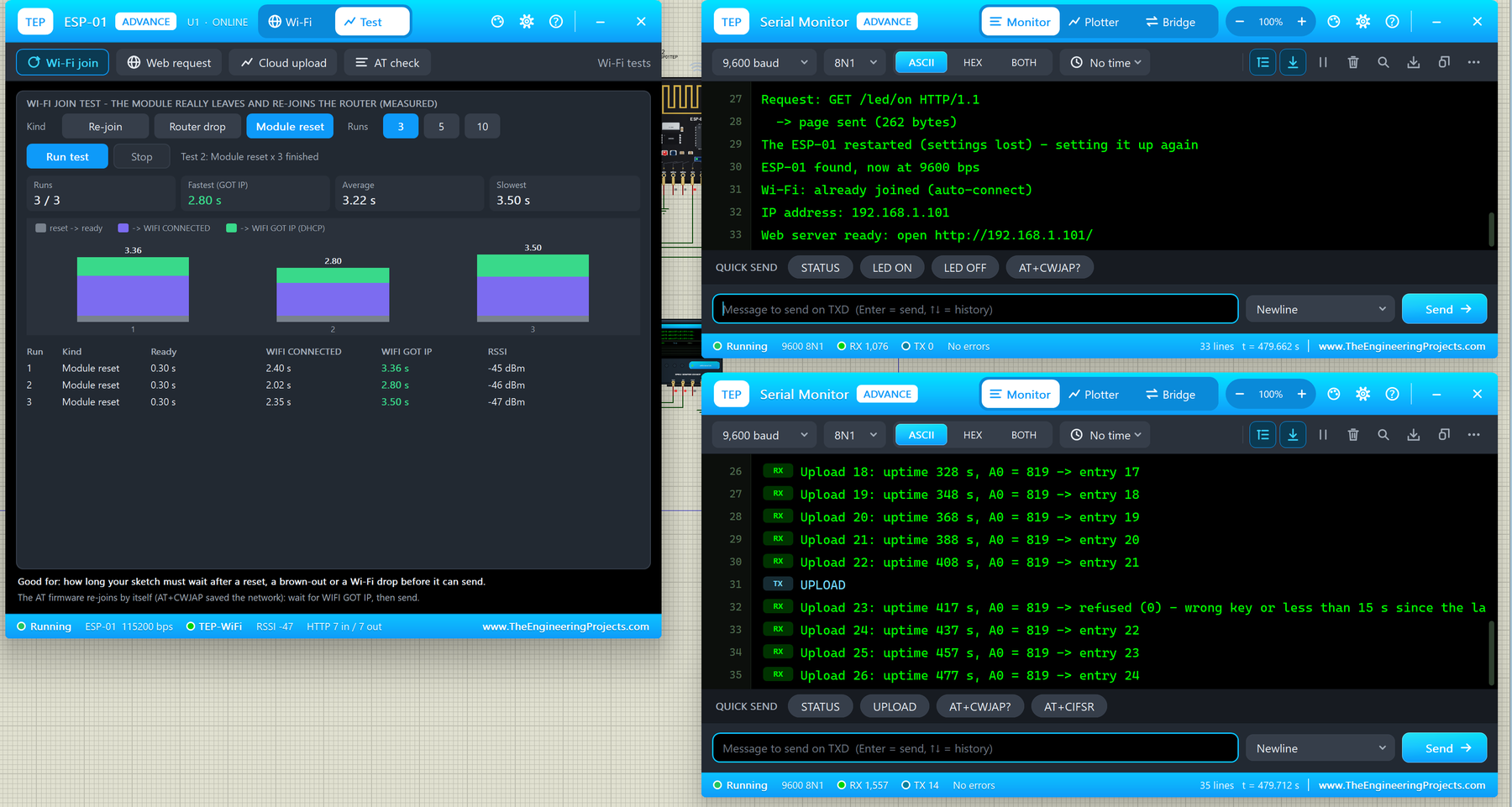
Within 30 s, the demo sketch printed "The ESP-01 restarted (settings lost) - setting it up again", switched the module to 9600 again, found it "already joined (auto-connect)" and printed "Web server ready" again. Good for: learning how long your sketch must wait after a reset, and testing your recovery code.
2. Web Request
This test checks your web server. Pick a page (/, /led/on or /led/off) and 3, 5 or 10 runs. The phone requests the page and times every step. I picked /led/on and 5 runs:
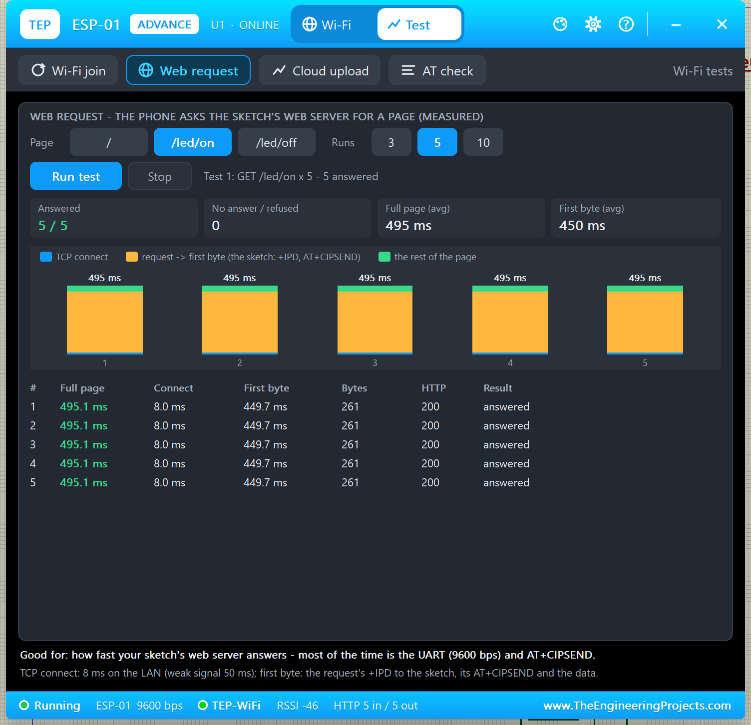
All five were answered: the TCP connection took only 8 ms, the first byte arrived after 450 ms and the full page (261 bytes, HTTP 200) after 495 ms. Most of that time is your sketch: it reads the +IPD request, sends AT+CIPSEND and pushes the page through the 9600 bps UART. Good for: seeing why a faster UART or a smaller page makes your web server snappier.
3. Cloud Upload Check
Cloud services such as IoT channel APIs accept one update every 15 seconds per key, and answer 0 to anything faster. The cloud upload check watches every /update request that reaches the virtual internet host. While it ran, I pressed UPLOAD in U4 to send one too early:
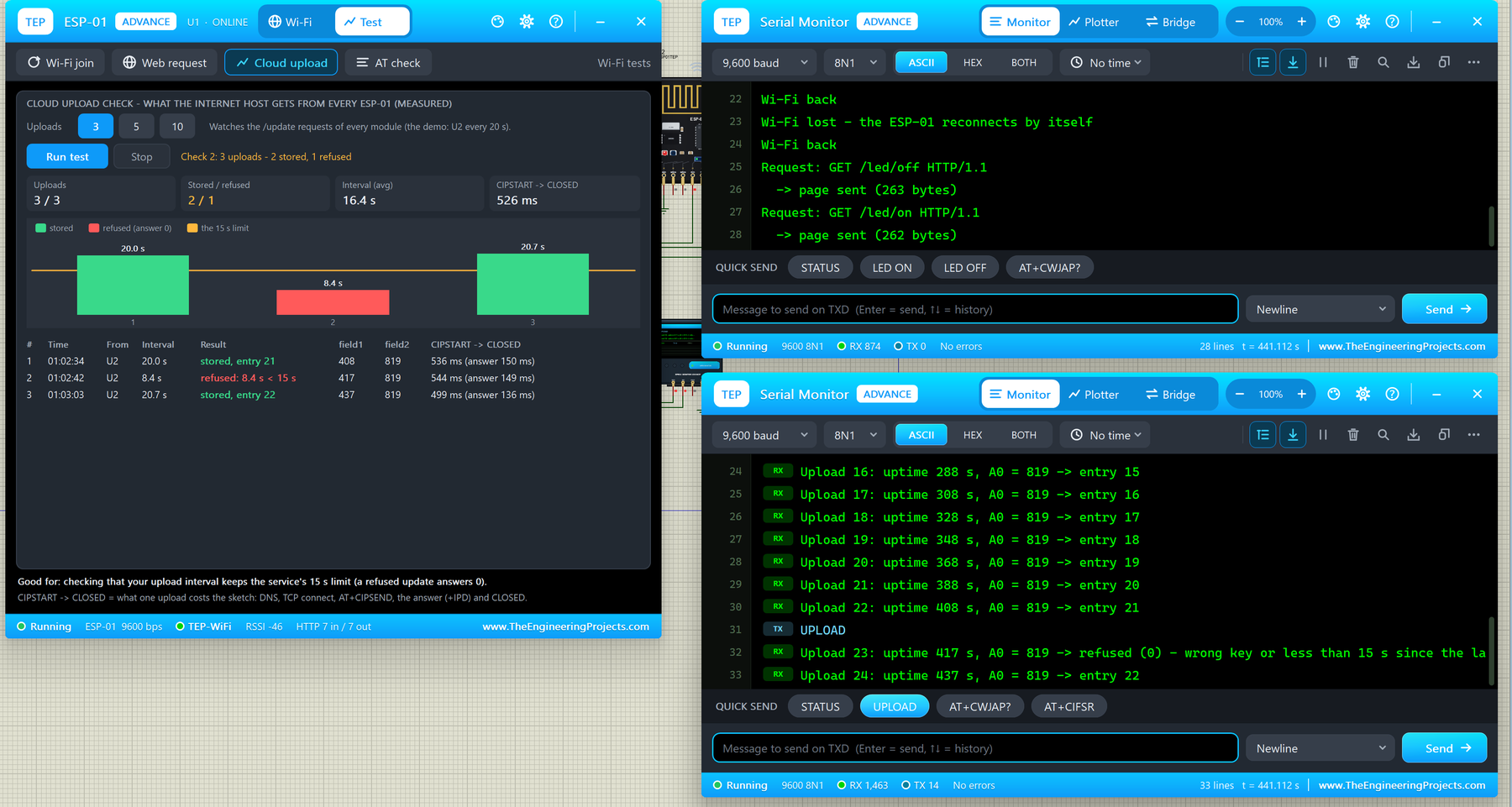
| # | Interval | Result | field1 | field2 | CIPSTART -> CLOSED |
|---|---|---|---|---|---|
| 1 | 20.0 s | stored, entry 21 | 408 | 819 | 536 ms (answer 150 ms) |
| 2 | 8.4 s | refused: 8.4 s < 15 s | 417 | 819 | 544 ms (answer 149 ms) |
| 3 | 20.7 s | stored, entry 22 | 437 | 819 | 499 ms (answer 136 ms) |
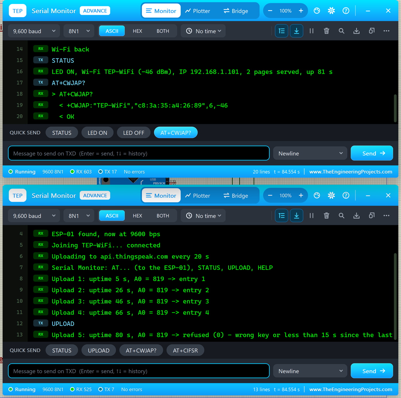
U4 printed "refused (0) - wrong key or less than 15 s since the last update" for the early one. Good for: checking that your upload interval respects the service's limit, and seeing what one upload costs your sketch (about half a second from AT+CIPSTART to CLOSED).
4. AT Check
The AT check shows what the module's read-only queries answer right now, plus the last 8 AT commands your Arduino sent, with replies and response times:
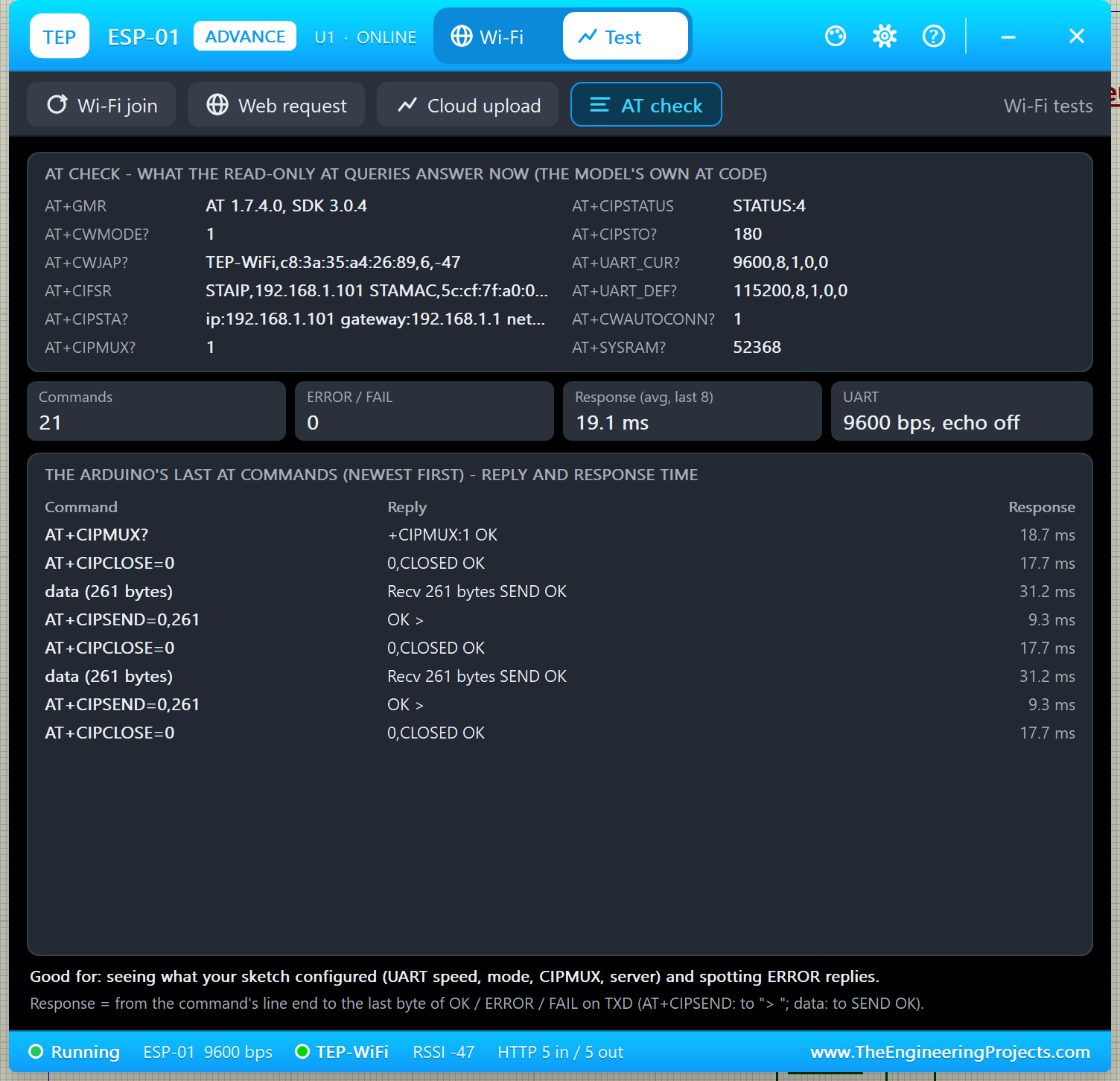
In my run: AT+GMR = AT 1.7.4.0, SDK 3.0.4; AT+CWMODE? = 1; AT+CWJAP? = TEP-WiFi, -47 dBm; AT+CIPMUX? = 1; AT+CIPSTATUS = STATUS:4; AT+UART_CUR? = 9600,8,1,0,0 while AT+UART_DEF? = 115200,8,1,0,0 (the sketch changed only the current speed); AT+CWAUTOCONN? = 1. The sketch had sent 21 commands with 0 ERROR, 19.1 ms on average. Good for: seeing what your sketch really configured.
Settings and Help
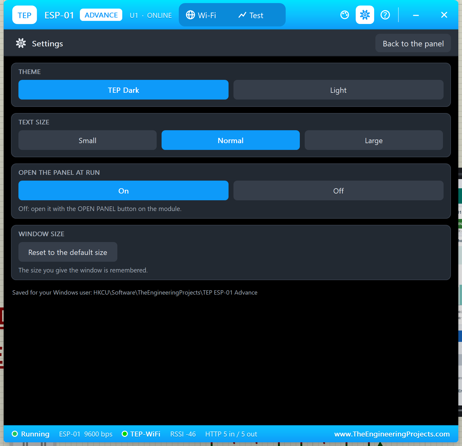
These pages work like in our SIM800L Library for Proteus and NEO-6M Library for Proteus. The gear icon opens Settings: theme (TEP Dark or Light), text size, open the panel at Run and the window size, saved for your Windows user.
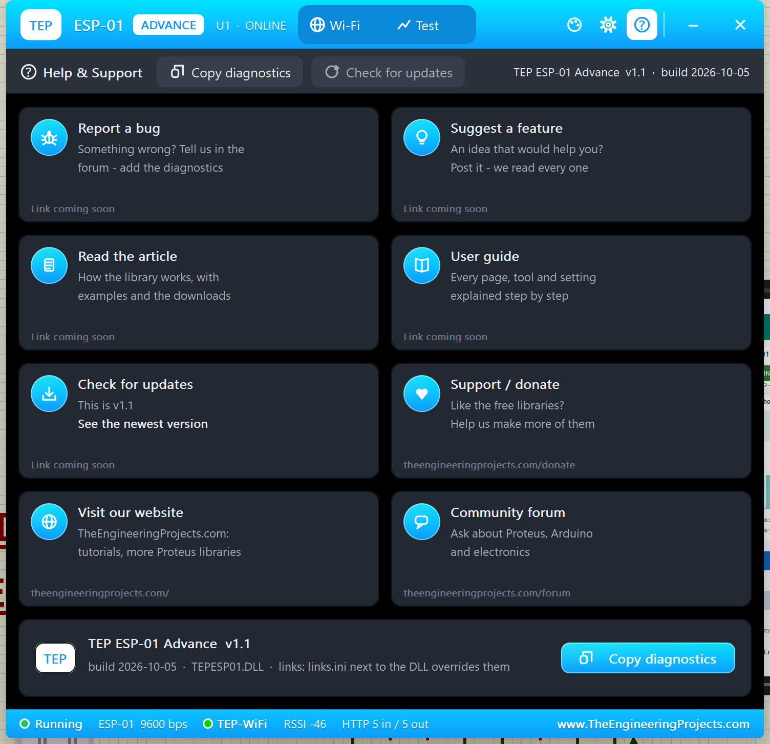
The ? icon opens Help & Support: eight cards (report a bug, suggest a feature, read the article, user guide, check for updates, support / donate, our website, community forum) and Copy diagnostics for a bug report.
ESP-01 with Arduino in Proteus
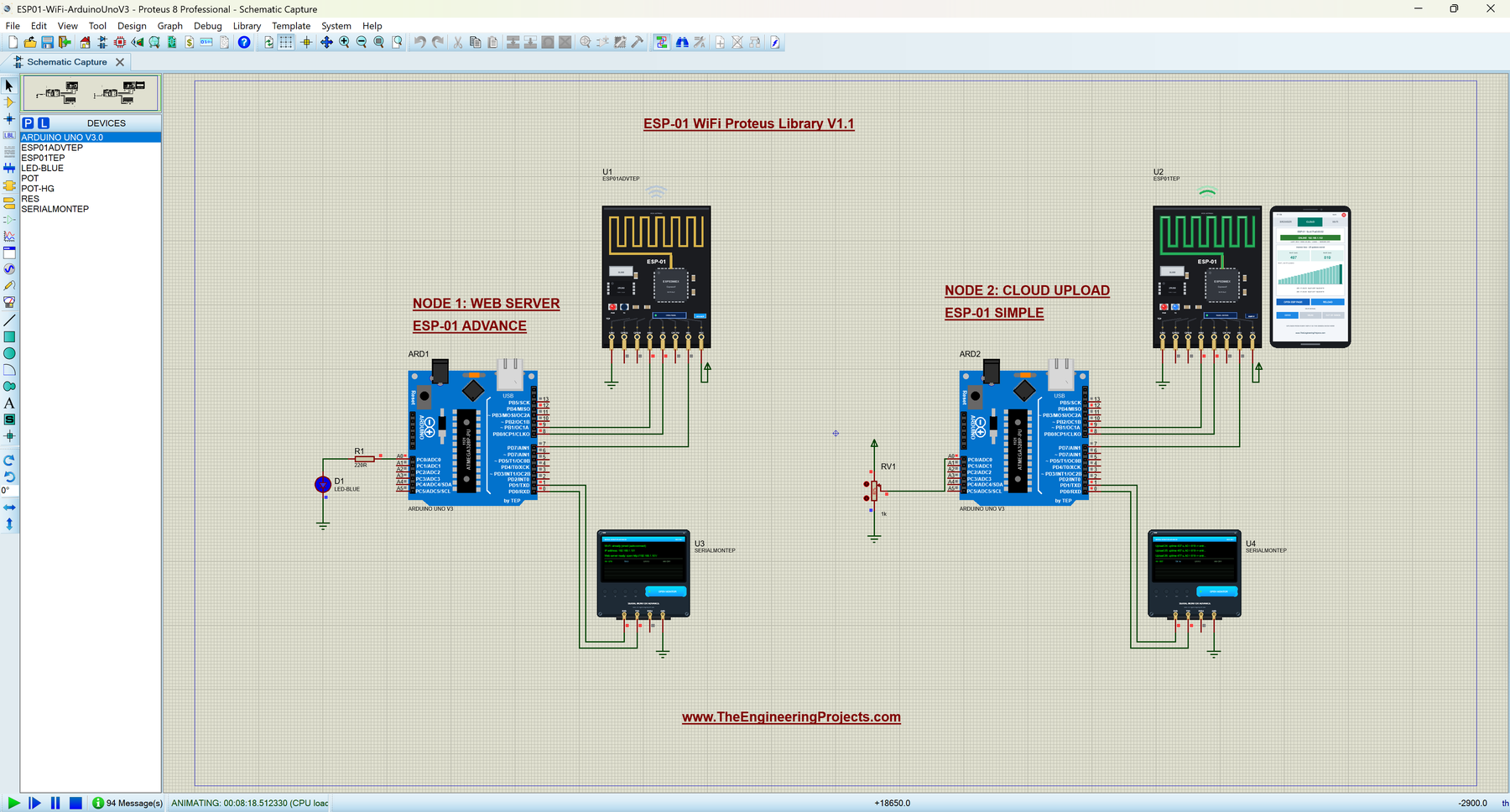
Now let's look at the demo. Open ESP01-WiFi-ArduinoUnoV3.pdsprj from the Proteus Simulation folder. It has two Arduino UNOs from our Arduino Library for Proteus V3.0:
- Node 1 (ARD1) runs
ESP01_Web_Serverwith the ESP-01 Advance (U1, 192.168.1.101), LED D1 with a 220 Ω resistor on A0 and Serial Monitor U3. - Node 2 (ARD2) runs
ESP01_Cloud_Uploadwith the ESP-01 Simple (U2, 192.168.1.102), a 1 k potentiometer RV1 on A0 and Serial Monitor U4.
Wiring
| From | To | Why |
|---|---|---|
| ESP-01 TXD | Arduino D8 | AltSoftSerial RX: answers and +IPD data |
| ESP-01 RXD | Arduino D9 | AltSoftSerial TX (and the one 115200 command) |
| ESP-01 RST | Arduino D7 | The sketch resets the module at start-up |
| ESP-01 VCC / GND | 3.3 V / ground | Power |
| CH_PD, GPIO0, GPIO2 | Open | The model pulls them up, like a working board |
| Serial Monitor RXD / TXD | Arduino D1 / D0 | Shows what the Arduino prints, sends what you type |
| Serial Monitor GND | Ground | Common ground (RXD2 is not used in this demo) |
Want to know more about these pins? Read our Introduction to Arduino UNO.
The 115200 bps Problem
The ESP-01's AT firmware starts at 115200 bps. A software serial port on a 16 MHz UNO cannot receive that reliably, so the sketches send one command at 115200 and then talk at 9600:
AT+UART_CUR=9600,8,1,0,0is sent with SoftwareSerial, whose output is timed by counted CPU cycles and is exact at 115200.- Then AltSoftSerial (Paul Stoffregen, MIT licence) takes D9 over and does all the work at 9600, receiving on D8.
Why not SoftwareSerial for everything? In Proteus 8.5 it cannot receive: it needs pin-change interrupts, which the Proteus 8.5 ATmega328P model never runs. And don't use D10 while AltSoftSerial runs. Here is that part of the sketch:
  esp.end();                           // D9 to SoftwareSerial for one command
  espFast.begin(115200);               // the ESP-01's factory speed
  espFast.print(F("AT+UART_CUR=9600,8,1,0,0\r\n"));
  espFast.end();
  esp.begin(9600);                     // AltSoftSerial takes D9 over
AT+UART_CUR is lost at every reset, so the module always starts at the factory speed. That is why the module reset test above made the sketch switch it again.
Sketch 1: The Web Server
After joining the Wi-Fi, ESP01_Web_Server.ino starts the server:
  command("AT+CIPMUX=1");              // several connections - needed for the server
  command("AT+CIPSERVER=1,80");
When the phone requests a page, the module prints +IPD with the request. The sketch reads the path and switches the LED:
    if (!strcmp(path, "/led/on")) digitalWrite(LED_PIN, HIGH);
    if (!strcmp(path, "/led/off")) digitalWrite(LED_PIN, LOW);
    sendPage(link, path);
sendPage() builds the HTML with the LED state and sends it with AT+CIPSEND, then closes the link with AT+CIPCLOSE.
Sketch 2: The Cloud Uploader
ESP01_Cloud_Upload.ino opens a TCP connection to the cloud host every 20 s and sends an HTTP GET with the uptime as field1 and the potentiometer as field2:
  snprintf_P(at, sizeof(at), PSTR("AT+CIPSTART=\"TCP\",\"%s\",80"), HOST);
  if (!command(at, 10000)) { Serial.println(F("  no connection to the server - next try in 20 s")); return; }
  char request[150];
  snprintf_P(request, sizeof(request), PSTR("GET /update?api_key=%s&field1=%lu&field2=%d HTTP/1.1\r\nHost: %s\r\nConnection: close\r\n\r\n"),
             API_KEY, uptime, a0, HOST);
Any host name resolves to our virtual internet host, which answers like a real IoT channel API: the entry number, or 0 when the update comes too early. On a real board, put your own network in WIFI_SSID / WIFI_PASS and your channel's Write API Key in API_KEY. If you change a sketch, compile it and load the new HEX file into the UNO; see How to get the HEX file from Arduino. New to Arduino? Start with our Arduino Tutorial for Beginners.
Serial Monitor Commands
| Command | Sketch | What it does |
|---|---|---|
| AT... | Both | Sent to the ESP-01 as typed; the answer lines are printed with " < " |
| STATUS | Both | Web server: LED, Wi-Fi + RSSI, IP, pages served; uploader: uploads stored / refused, A0, next upload |
| LED ON / LED OFF | Web server | Switch the LED from the monitor |
| UPLOAD | Uploader | An upload now (refused within 15 s of the last one) |
| HELP | Both | The command list |
How to Run the Demo
- Open
Proteus Simulation\ESP01-WiFi-ArduinoUnoV3.pdsprj(keep the two .hex files and both DLLs beside it). - Press Run. Both Serial Monitors open at 9600 baud, and so does U1's pop-up.
- After about 6 s, U3 prints "Web server ready: open http://192.168.1.101/" and U4 the first upload.
- In U1's pop-up, tap OPEN ESP PAGE, then LED ON / LED OFF on the page, and watch D1 and U3.
- Turn RV1 and watch field2 on U2's CLOUD tab. Then try the Test tab.
Simulation Results
U3 (the web server) shows the start-up and every request:
ESP-01 web server v1.1
www.TheEngineeringProjects.com
Resetting the ESP-01...
ESP-01 found, now at 9600 bps
Joining TEP-WiFi... connected
IP address: 192.168.1.101
Web server ready: open http://192.168.1.101/
Serial Monitor: AT... (to the ESP-01), STATUS, LED ON, LED OFF, HELP
Request: GET / HTTP/1.1
  -> page sent (262 bytes)
Request: GET /led/on HTTP/1.1
  -> page sent (261 bytes)
U4 (the uploader) prints one line per upload, like "Upload 1: uptime 5 s, A0 = 819 -> entry 1". Here are both monitors after I used the quick buttons STATUS and AT+CWJAP? on U3 and UPLOAD on U4:
LED ON, Wi-Fi TEP-WiFi (-46 dBm), IP 192.168.1.101, 2 pages served, up 81 s
> AT+CWJAP?
  < +CWJAP:"TEP-WiFi","c8:3a:35:a4:26:89",6,-46
  < OK
Read all about the monitor in TEP Serial Monitor Advance for Proteus.
ESP-01 AT Commands Supported
| Group | Commands |
|---|---|
| Basic | AT, AT+RST, AT+GMR, ATE0/1, AT+RESTORE, AT+UART_CUR / AT+UART_DEF, AT+SYSRAM? |
| Wi-Fi | AT+CWMODE, AT+CWLAP, AT+CWJAP (WIFI CONNECTED / WIFI GOT IP, +CWJAP:2 / 3 errors), AT+CWQAP, AT+CWAUTOCONN, AT+CIFSR, AT+CIPSTA? |
| TCP / UDP | AT+CIPMUX, AT+CIPSTART, AT+CIPSEND ("> ", SEND OK), +IPD, AT+CIPCLOSE, AT+CIPSERVER, AT+CIPSTO, AT+CIPSTATUS, AT+CIPDINFO |
| Network tools | AT+CIPDOMAIN (DNS), AT+PING, AT+CIPSNTPCFG / AT+CIPSNTPTIME? |
| Power | AT+GSLP (deep sleep), the RST / CH_PD / GPIO0 pins |
Line endings: the AT firmware needs CR + LF after every command (println or "\r\n"). Sending a command while AT+CWJAP is still running gives "busy p...".
Troubleshooting
"No answer from the ESP-01"
TXD must go to D8 and RXD to D9, and the sketch must switch the module to 9600 first (see the 115200 bps problem).
The Phone Says "Connection refused"
The sketch has not sent AT+CIPMUX=1 and AT+CIPSERVER=1,80.
Uploads Answer 0
A missing api_key or fields, or less than 15 s since the last stored update with the same key.
My Sketch Stops Working After a Reset
The module is back at 115200 bps without its settings. Switch it to 9600 and set it up again, like the demo sketches do every 30 s.
No Phone, No Pop-Up or No Monitor
TEPESP01.DLL or TEPSERIALMON.DLL is missing from MODELS and the project folder. For the Advance, click OPEN PANEL or turn "Open the panel at Run" back on in Settings.
Things to Know Before Using a Real ESP-01
- 3.3 V only: 5 V on VCC or on its pins damages the ESP-01. Use a 3.3 V regulator that can deliver at least 300 mA; the UNO's 3.3V pin cannot supply that.
- Logic level: put a divider between the Arduino's D9 and RXD, for example 1 k from D9 to RXD and 2 k from RXD to GND (about 3.3 V). TXD can go straight to D8.
- CH_PD: tie it to 3.3 V on a plain ESP-01 (the ESP-01S has the pull-ups on the board).
- Brown-outs: a 10 - 100 µF capacitor across VCC / GND helps against resets while transmitting.
Limitations of the Simulation
- The ESP-01 is modelled with its AT firmware, controlled by an Arduino. Programming the ESP8266 itself (Arduino core for ESP8266, NodeMCU) is not simulated.
- Not modelled: the soft-AP side, SSL / TLS, transparent mode, a static IP, WPS / SmartConfig, firmware updates, radio range and supply current. The router, the networks and the internet host are simulated.
- Tested in Proteus 8.5 (the demo and every Proteus screenshot in this article) and with 802 automatic checks on the PC; Proteus 7 is not supported.
Want to connect without Wi-Fi? Try our SIM800L Library for Proteus for GSM, or our HC-12 Library for Proteus and HC-05 Library for Proteus.
So, that was all about the ESP-01 Wi-Fi Library for Proteus V1.1. I hope the virtual phone, the web server, the cloud uploads and the test tools make IoT projects much easier to understand. Please share your feedback in the comments or in our forum, and if you have any questions, ask in the comments and I will help you out. Till the next tutorial, take care and have fun!