Hello friends, I hope you are doing well. This is the sixteenth tutorial in our series on how to create a Proteus library. In the previous tutorial, How to Create an Animated Component in Proteus, our Traffic Light Module learned to show its lamps: state symbols, a common symbol and real time current probes in the model. That part is an indicator; it shows what the circuit does. Today, we build the opposite kind of part, one that the user operates with the mouse while the simulation runs. Our topic is how to design a user interactive library in Proteus.
Our example is a new member of our TEPTUTORIAL library: a Push Button Module with the pins GND, VCC and OUT, like the small button boards sold for Arduino projects. We will look at the three markers that make a part clickable, INCREMENT, DECREMENT and TOGGLE, at the STATE property that stores what the user did, and at the RTSWITCH primitive that turns that state into a real connection in the model. Then we draw the module, make its state symbols, store it with Make Device, compile its model and use it to switch the red lamp of our traffic light.
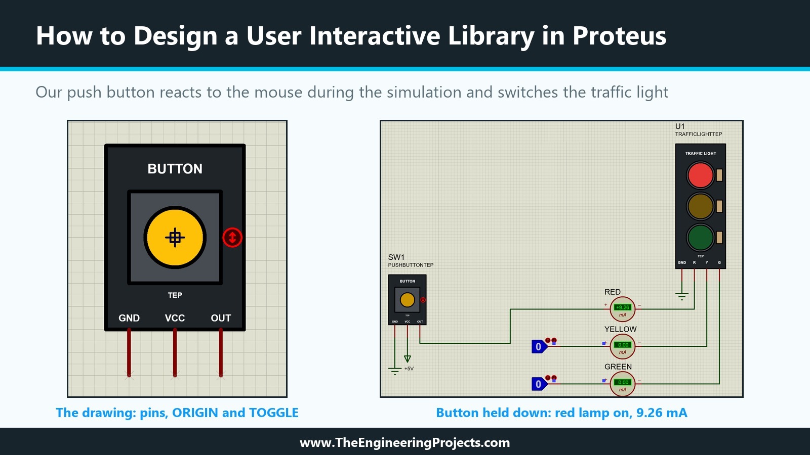
Everything shown here was done in Proteus 8.5 Professional on our PC. The picture below shows the result: on the left, the drawing of the module with its pins and markers; on the right, the button held down during a simulation, with the red lamp lit and 9.26 mA in the meter.
What Is a User Interactive Component in Proteus?
The Proteus help divides the animated parts of an interactive simulation into two groups. Indicators display a state that changes according to something measured in the circuit, like our traffic light or an LED. Actuators let the user set their state, and that state then changes something in the circuit, like a switch, a push button, a potentiometer or a keypad. In this tutorial, user interactive and actuator mean the same thing.
Indicators and Actuators Use the Same Machinery
Both kinds are active components. They have an ACTIVE line in the device script, a set of state symbols named after a stem, and usually a common symbol, exactly as we built them in the previous tutorial. The difference lies in who sets the state. For an indicator, a probe in the model sets it. For an actuator, the user sets it with the mouse, Proteus stores it in a property of the placed part, and the model reads that property.
How Proteus Shows That a Part Can Be Clicked
The help gives the rule in one sentence: actuators are designated by small red marker symbols, which can be clicked with the mouse to operate the control. With a wheel mouse, you can also point at an actuator and roll the wheel. Those red symbols are markers, the same kind of object as the ORIGIN marker we used in every state symbol so far.
The Three Actuator Markers: INCREMENT, DECREMENT and TOGGLE
When we placed the Origin markers in the previous tutorial, the Markers list of Proteus 8.5 offered ORIGIN, NODE, BUSNODE, LABEL, PINNAME, PINNUM, INCREMENT, DECREMENT and TOGGLE. The last three are the actuator markers. Each one is a hot spot: a place on the part where a mouse click changes the state.
INCREMENT and DECREMENT
The help describes INCREMENT as a marker used in creating Active Component simulator models that defines a hot spot for incrementing the state variable, and DECREMENT as the same for decrementing it. On the sheet, they look like a red circle with an arrow pointing up or down. A part with several positions needs both: one click steps it up, the other steps it down.
TOGGLE
The help page on markers stops at DECREMENT, but TOGGLE is in the list and Labcenter's own parts use it. Its red circle has a double arrow. To find out how Labcenter uses the three markers, we searched the device records in ACTIVE.LIB for them. The pattern is very clear:
- INCREMENT and DECREMENT appear on every part whose description ends in Latched Action, such as the SPST, SPDT, DPST and DPDT switches and the latched LOGICSTATE, and on parts that step through positions, such as the rotary switches, the thumbwheel switches and the jumpers.
- TOGGLE appears on the parts described as Momentary Action, the momentary versions of the same switches and of the logic state source, and on BUTTON, the SPST push button.
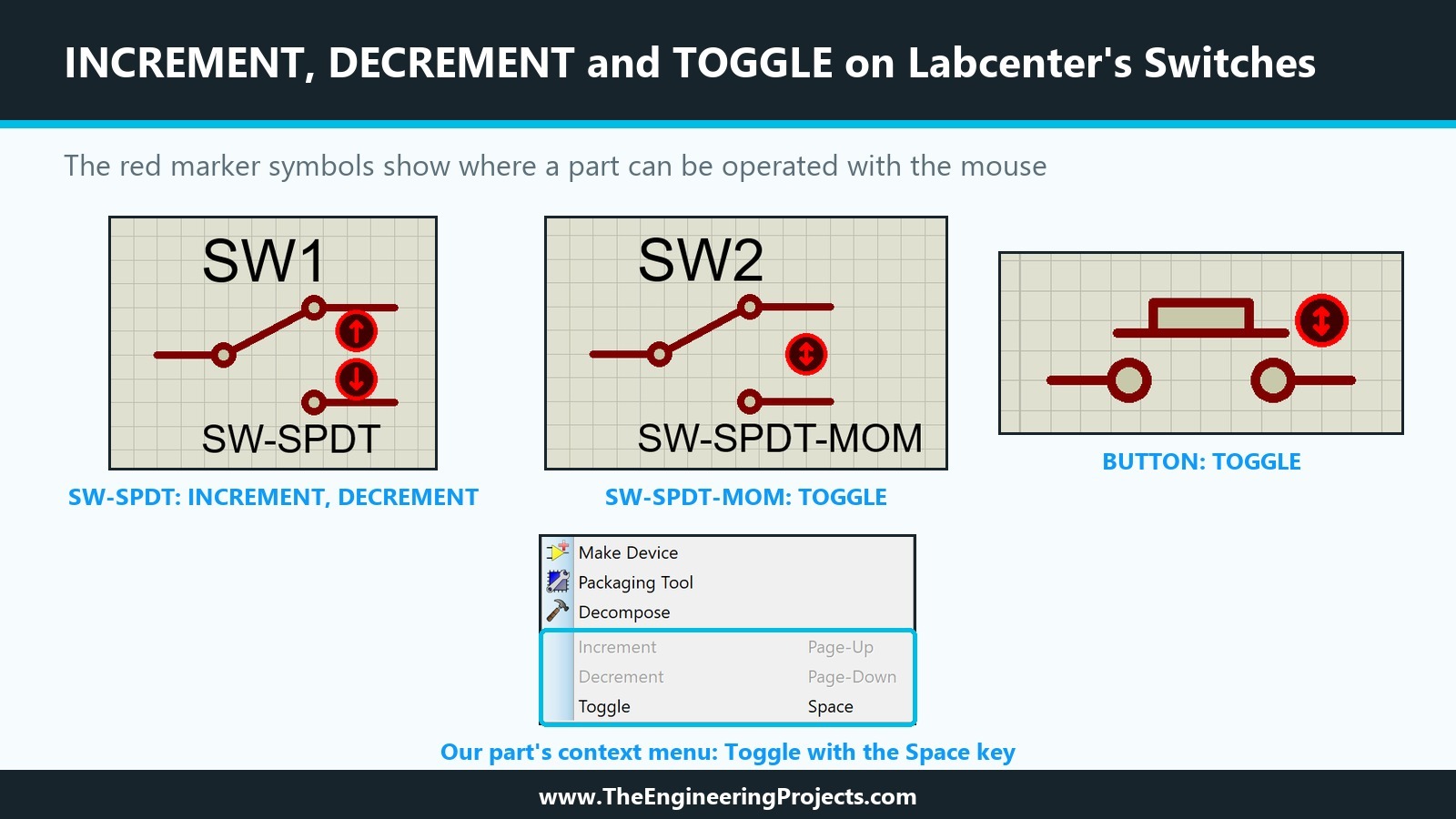
The picture shows the difference on the sheet: SW-SPDT has an up and a down arrow, while SW-SPDT-MOM and BUTTON have the double-arrow toggle marker.
Keyboard Shortcuts and the Context Menu
The markers also add commands to the part's context menu. When we right-clicked our finished push button, the menu ended with Increment (Page-Up), Decrement (Page-Down) and Toggle (Space). Only Toggle was active, because our part has only a TOGGLE marker, while a LOGICSTATE showed Increment and Decrement active. During the simulation, pointing at our button and pressing Space toggled it, just like a click on its marker.
How Does an Actuator Change the Circuit?
A click changes a number. Something in the model must turn that number into an electrical effect, and Labcenter's own parts show how.
The STATE Property
The device script of Proteus's BUTTON starts with ACTIVE=BUTTON,2 and defines its first property as STATE, described as Active State, hidden, of type integer, with the default STATE=0. The placed part carries this property, the clicks change it, and the model sees it like any other property. BUTTON has the symbols BUTTON_0 and BUTTON_1 for its two states, each with an Origin marker, exactly the naming rule of the previous tutorial without the bitwise part.
The RTSWITCH Primitive
The other properties of BUTTON reveal its model: PRIMITIVE=PASSIVE,RTSWITCH, R(0)=100M, R(1)=100m and TSWITCH. RTSWITCH is in the REALTIME library, which describes it as a real time interactive switch primitive in the category Modelling Primitives, sub-category Realtime (Actuators). It is a resistor whose value depends on its STATE: R(0) is used in state 0, R(1) in state 1 and so on, and TSWITCH is the switching time. Its own defaults already contain STATE=<STATE>, which means: take the state from the parent part.
How Labcenter's Switch Models Use It
In the model library ACTIVE.LML, Labcenter's switch models are built from RTSWITCH parts. An SPST switch is one RTSWITCH with R(0)=<ROFF> and R(1)=<RON>. A changeover contact adds a second RTSWITCH with the two values swapped. The three position rotary switch uses three RTSWITCH parts on a common terminal, and each of them has RON only in its own state: R(0)=<RON> in the first, R(1)=<RON> in the second, R(2)=<RON> in the third, ROFF everywhere else. With these patterns, a schematic model can turn any number of user states into connections.
Planning Our Push Button Module
Our traffic light already uses its ACTIVE line for the lamps, and a part has only one ACTIVE line. So the interactive part of this tutorial is a second part in the same library, a Push Button Module that can drive the traffic light, or later an Arduino input.
Pins and Behaviour
The module has three pins, GND, VCC and OUT. While the button is pressed, OUT is connected to VCC. While it is released, a 10k pull-down resistor on the module holds OUT at GND, so a microcontroller input reads a clean LOW instead of floating. The pull-down value becomes a property, RPULL, so that a user can change it without editing the model, the same idea as the lamp resistors of our traffic light.
Momentary and Latched in One Part
We gave the part a TOGGLE marker, like Labcenter's BUTTON. As our tests later show, this gives two ways to use it: pressing the button with the mouse works like a real push button, on while the mouse button is held, and a click on the small red marker latches it until the next click.
How to Design a User Interactive Library in Proteus: Step by Step
We built the module in seven steps, in the Traffic Light Module test project, which keeps our parts and their source drawings together.
Step 1: Draw the Module
We drew the module with the 2D graphics tools from the third and fourth tutorials, centred on an empty part of the sheet:
- A board of 600 by 800 thou, filled with 31, 36, 40 like our traffic light board.
- A housing of 400 by 400 thou in the middle, filled with 70, 76, 82.
- A cap, a circle with a radius of 130 thou, filled with 255, 193, 7.
- White texts: BUTTON at the top, TEP under the housing, and GND, VCC and OUT at the bottom edge above the pins.
Step 2: Add the Pins and the Markers
The pins are DEFAULT pins rotated by 90 degrees, 200 thou long, pointing down from the bottom edge of the board, as in the sixth tutorial. We named them GND, VCC and OUT with the numbers 1, 2 and 3. GND and VCC got the type PP - Power Pin, OUT the type OP - Output, and Draw name and Draw number were unticked, because the board already shows the names.
The ORIGIN Marker
This time, we placed an ORIGIN marker in the part itself, at the centre of the cap. In the seventh tutorial, without a marker, Proteus used the end of the GND pin as the origin of the traffic light. With the marker, the placed push button follows the mouse by the centre of its cap, and every state symbol can simply have its Origin marker at the cap centre too.
The TOGGLE Marker
From the Markers list, we placed one TOGGLE marker 250 thou to the right of the cap centre, in the free space between the housing and the edge of the board. Our first try at the bottom right corner covered part of the OUT text, so check the position before you continue. As the help describes for all markers, the first click on the sheet enters placement mode and the second one places the marker.
Step 3: Make the State Symbols
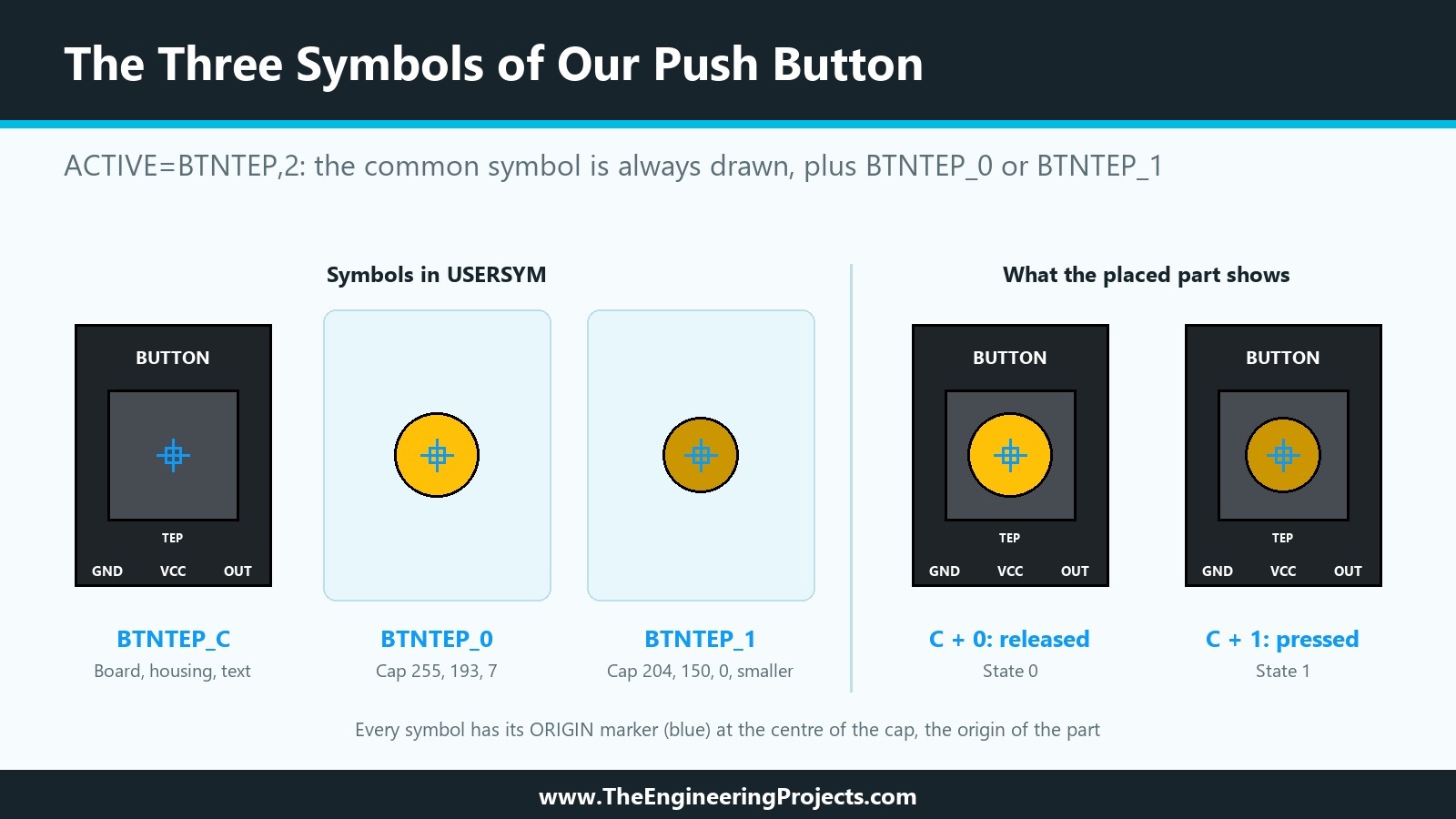
The part has two states, released and pressed, and a common symbol for everything that does not change. Following the naming rule of the previous tutorial, with the stem BTNTEP, the symbols are BTNTEP_0, BTNTEP_1 and BTNTEP_C.
The Released and the Pressed Cap
We tagged the cap and its Origin marker and placed two copies of them in an empty area with Block Copy. With the first copy tagged, Library, Make Symbol stored BTNTEP_0 in USERSYM. For the second copy, we opened the circle's properties, set the radius to 115 thou and the fill colour to 204, 150, 0, a darker amber, so the pressed cap looks smaller and pushed in. Make Symbol stored it as BTNTEP_1.
The Common Symbol
For BTNTEP_C, we copied the whole module again, deleted the pins, the cap and the TOGGLE marker from the copy, tagged the board, the housing, the texts and the Origin marker, and stored them with Make Symbol. The pins are not needed in the common symbol, because Proteus draws the part's pins itself.
Step 4: Store the Part with Make Device
With the module, its pins and both markers tagged, we opened Library, Make Device.
Device Properties
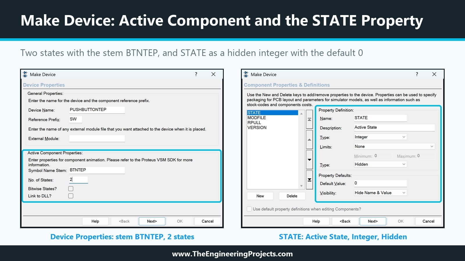
We entered PUSHBUTTONTEP as the device name and SW as the reference prefix, the prefix Labcenter uses for switches. In the Active Component Properties, the Symbol Name Stem is BTNTEP and the No. of States is 2. Bitwise States stays unticked, because the button is one element with two states, not a set of independent elements, and Link to DLL stays unticked as well. The part needs no PCB package for now, so we skipped the Packagings page.
Component Properties
On the Component Properties & Definitions page, the New button opens a list of predefined property names, and STATE is one of them. Choosing it filled in the description Active State and the type Hidden; we changed the data type from String to Integer and set the default value to 0, which gives exactly the definition of Labcenter's BUTTON. Then we added:
- MODFILE from the same list, LISA Model File, read only, with the default PUSHBUTTON, as in the fourteenth tutorial.
- RPULL as a Blank Item, with the description Pull-down Resistor, type String, Normal, default 10k.
- VERSION as a Blank Item, read only, default 1.0.
Indexing and Library
On the last page, we chose the category Switches & Relays, the sub-category Switches and our manufacturer, The Engineering Projects, typed the description Push Button Module (TEP Tutorial) and stored the part in TEPTUTORIAL. As with the traffic light, Make Device copied the three symbols into TEPTUTORIAL.LIB next to the device. Here is the device part of the script, read from the library file:
; PUSHBUTTONTEP version 1.0, read from TEPTUTORIAL.LIB after Make Device
{*DEVICE}
{PREFIX=SW}
{ACTIVE=BTNTEP,2}
{*PROPDEFS}
{STATE="Active State",HIDDEN INT}
{MODFILE="LISA Model File",READONLY STRING}
{RPULL="Pull-down Resistor",STRING}
{VERSION="Version",READONLY STRING}
{*INDEX}
{CAT=Switches & Relays}
{SUBCAT=Switches}
{MFR=The Engineering Projects}
{DESC=Push Button Module (TEP Tutorial)}
{*COMPONENT}
{STATE=0}
{MODFILE=PUSHBUTTON}
{RPULL=10k}
{VERSION=1.0}

; Symbols stored next to the device: BTNTEP_C, BTNTEP_0, BTNTEP_1
Step 5: Draw the Model
Like the traffic light, the button gets a schematic model in a project of its own. We created the project PUSHBUTTON with File, New Project, with a schematic from the DEFAULT template, no PCB layout and no firmware.
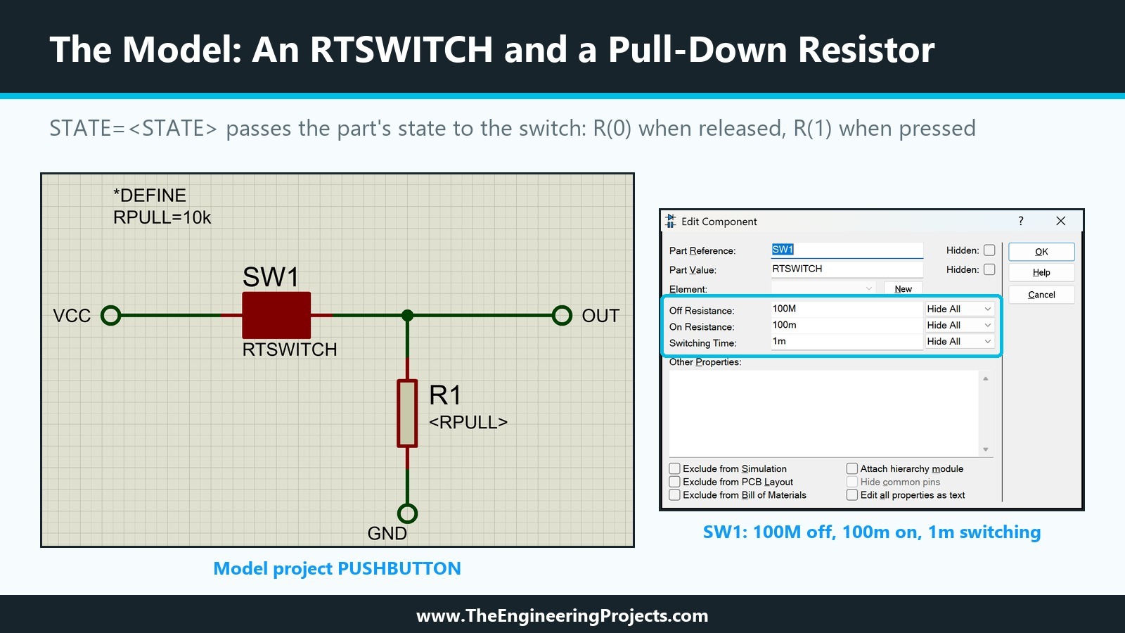
The Model Circuit
Pick Devices finds RTSWITCH by name in the REALTIME library, listed as Analogue Primitive [RTSWITCH]. We placed one RTSWITCH and one RES from the DEVICE library, and three DEFAULT terminals named VCC, OUT and GND, the names of the pins of our part. The switch sits between VCC and OUT, and the resistor between OUT and GND. We left the switch's values as they come: Off Resistance 100M, On Resistance 100m and Switching Time 1m, the same values as Labcenter's BUTTON. Its STATE property does not appear in the dialogue, because it is hidden, but it is already set to <STATE>.
The Pull-Down Resistor and Its Default
The resistor's value is <RPULL>, so it takes the RPULL property of the placed part. As a default, a script block with the two lines *DEFINE and RPULL=10k sits on the model sheet, as in the fourteenth tutorial.
Step 6: Compile the Model
After saving the project, Tool, Model Compiler opened the Compile Model dialogue in the MODELS folder with PUSHBUTTON as the file name, and Save wrote PUSHBUTTON.MDF, 510 bytes:
LISA MODEL DESCRIPTION FORMAT 8.0
=================================
Design:   PUSHBUTTON.pdsprj
Doc. no.: <NONE>
Revision: <NONE>
Author:   <NONE>
Created:  10/4/2026
Modified: 10/4/2026

*PROPERTIES,1
RPULL=10k

*MODELDEFS,0

*PARTLIST,2
R1,RES,<RPULL>,PRIMITIVE=ANALOG,PRIMTYPE=RESISTOR
SW1,RTSWITCH,RTSWITCH,PRIMITIVE=PASSIVE,R(0)=100M,R(1)=100m,STATE=<STATE>,TSWITCH=1m

*NETLIST,3
VCC,2
VCC,GT
SW1,PS,1

OUT,3
OUT,GT
SW1,PS,2
R1,PS,2

GND,2
GND,GT
R1,PS,1
The part list is the whole idea of this tutorial in two lines: the resistor takes RPULL, and the switch takes STATE from the placed part, using 100M in state 0 and 100m in state 1. The netlist connects the switch's pin 1 to VCC, its pin 2 and the resistor to OUT, and the resistor's other end to GND.
Step 7: Place the Part and Check It
Back in the test project, we picked PUSHBUTTONTEP from TEPTUTORIAL and placed it as SW1. The yellow cap and the red TOGGLE marker appeared, but the dark board had vanished; only the housing, the cap and the white texts, almost invisible on the paper, were left.
A Common Symbol Must Contain Everything That Stays
The cause was our tag box for BTNTEP_C. It had cut through the bottom edge of the board, and a tag box only tags objects that lie completely inside it. The board was never part of the common symbol. We tagged the copy again with a bigger box and stored BTNTEP_C once more. Proteus asked whether to replace the symbol in the disk library and whether to update all instances on the schematic; we answered Yes and OK.
The placed SW1 still had no board. Make Device had copied the old symbol into TEPTUTORIAL.LIB, and the part used that copy. So we decomposed SW1, tagged all of its pieces together with its NAME=PUSHBUTTONTEP script, and ran Make Device again. The wizard came up with every field already filled in, and when we confirmed that the existing device should be replaced, the new copy of BTNTEP_C went into the library. A freshly placed SW1 showed the complete module. If Make Device opens with empty fields after a decompose, the script was not fully inside the tag box.
How to Test the User Interactive Part
For the test, we used the circuit of the previous tutorial. The red LOGICSTATE was deleted, and SW1 took its place: OUT goes to the RED ammeter and on to the R pin of our Traffic Light Module U1, VCC goes to a +5V power terminal and GND to a ground terminal. The yellow and green inputs stayed on their LOGICSTATE parts, both at 0.
Press and Hold
After Run, the cap was yellow, the red lamp dark and the RED ammeter at 0.00 mA, because the switch was open and the pull-down held OUT at ground. Then we pressed the left mouse button on the part and kept it down. The cap changed to the darker pressed picture, the red lamp lit and the meter showed 9.26 mA. As soon as we released the mouse button, the cap returned, the lamp went dark and the meter fell back to 0.00 mA.
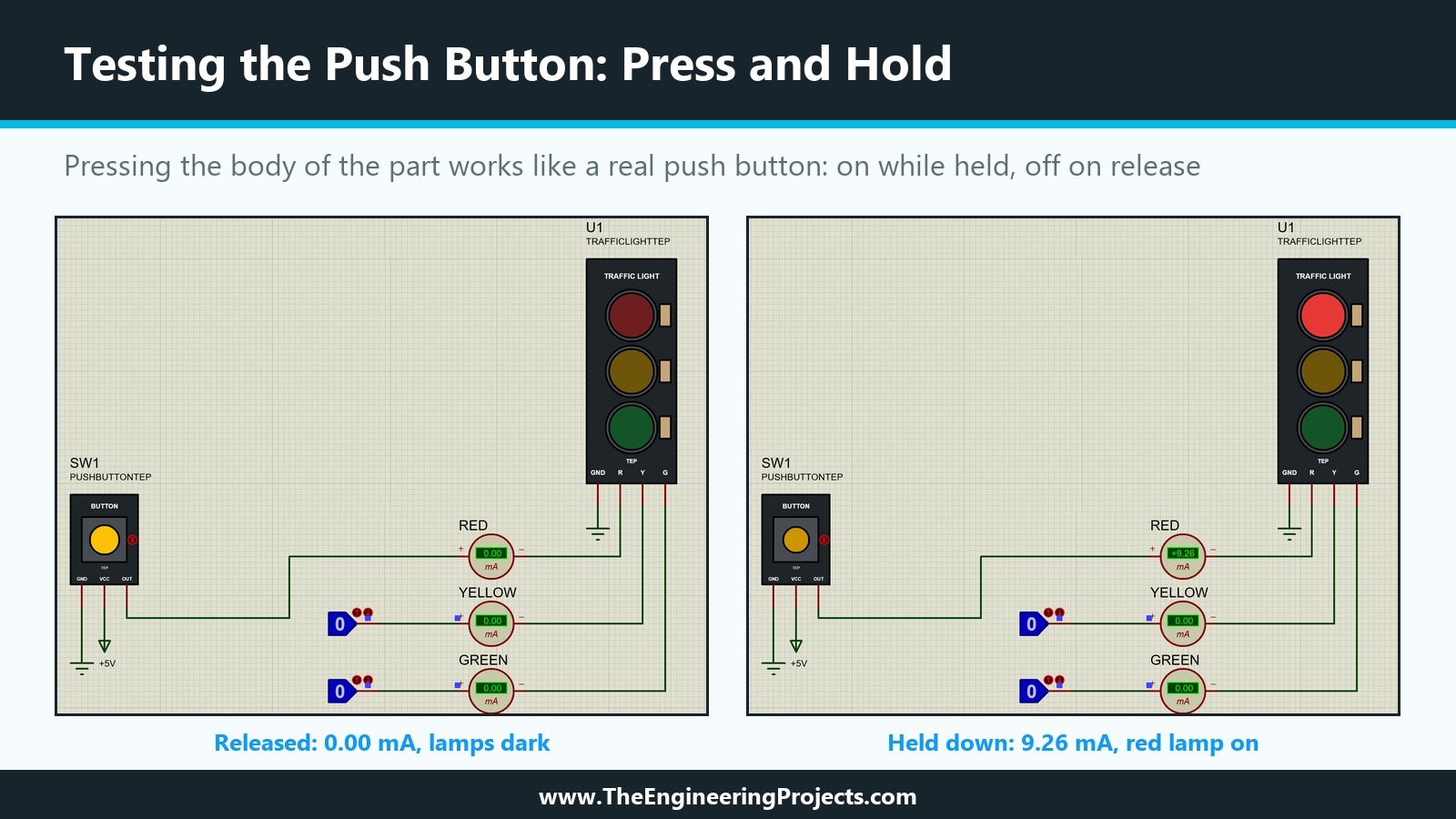
The 9.26 mA is exactly the value we measured from a +5V terminal in the thirteenth tutorial, while the LOGICSTATE of the previous tutorial gave 9.23 mA. The 100 milliohm on resistance of the switch is negligible next to the 330 ohm lamp resistor, so our button passes the supply straight through, as a real button does.
Latch with the TOGGLE Marker
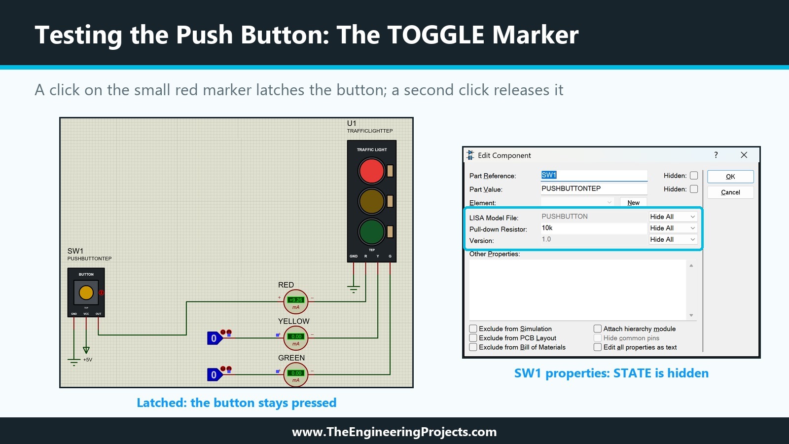
Next, we clicked the small red TOGGLE marker once and moved the mouse away. The button stayed pressed, with the red lamp on and 9.26 mA in the meter. A second click on the marker released it. Pointing at the part and pressing Space did the same: the first press latched it, the second released it.
What Happens After Stop
The simulation log showed only the usual start messages, no warnings. The help adds one more detail about stopping a simulation: indicators are reset to their inactive states, but actuators keep their existing settings. We saw it with the green LOGICSTATE, which we had switched to 0 during the run and which still showed 0 after Stop. By the same rule, a button latched with its TOGGLE marker keeps its state for the next run, so release it before you stop if you want a clean start.
How to Make a Part with More Than Two Positions
Our button needs only two states and one marker. For a selector with three positions, the same method works with three changes, all of which Labcenter's rotary switches show:
- Set No. of States to 3 and draw three state symbols, STEM_0, STEM_1 and STEM_2.
- Use an INCREMENT and a DECREMENT marker instead of TOGGLE, so the user can step through the positions in both directions.
- In the model, give each output its own RTSWITCH with the on resistance only in its own state, for example R(0)=100m, R(1)=100M, R(2)=100M for the first output, and the same pattern shifted for the others.
The rotary switch models in ACTIVE.LML follow exactly this pattern, and a potentiometer model even uses eleven resistance values in one RTSWITCH to step through its positions.
Common Mistakes When Designing an Interactive Part in Proteus
| Problem | Cause | Solution |
|---|---|---|
| Clicking the part does nothing | No INCREMENT, DECREMENT or TOGGLE marker in the part | Add the marker to the drawing before Make Device |
| The picture changes, but the circuit does not | The model does not use the state | Give the RTSWITCH STATE=<STATE> and a STATE property to the part |
| The board disappears when the part is placed | The board is missing from the common symbol | Tag the whole board, then store STEM_C again |
| A remade symbol does not show on the part | The part uses the copy stored by Make Device | Run Make Device again after changing a symbol |
| Make Device opens with empty fields after a decompose | The NAME script was not inside the tag box | Tag the script completely together with the graphics |
| The output floats while the button is released | No pull-down resistor in the model | Add a resistor from OUT to GND with a default value |
In the Next Tutorial
We now have both kinds of active parts in our library: a Traffic Light Module that shows what the circuit does, and a Push Button Module that the user operates with the mouse. Everything so far was built from Proteus's own primitives. In the next tutorial, How to Create a Proteus Simulation Model DLL in C++, we look at the other way to give a part its behaviour, a model written in code.
FAQ
How do I make a clickable part in Proteus?
Make it an active component with a STATE property, add an INCREMENT, DECREMENT or TOGGLE marker to its drawing before Make Device, and use STATE=<STATE> in its model, for example on an RTSWITCH primitive.
What is the difference between INCREMENT and TOGGLE in Proteus?
INCREMENT and DECREMENT step the state up or down and are used by Labcenter's latched and multi-position parts. TOGGLE is used by its momentary parts: pressing the part works while the mouse button is held, and a click on the marker latches it.
What is RTSWITCH in Proteus?
A real time interactive switch primitive from the REALTIME library. It is a resistance that takes the value R(0), R(1) and so on according to its STATE, and Labcenter builds its switch models from it.
Why does my interactive part not change the circuit?
The clicks only change the STATE property. The model must use it, for example through STATE=<STATE> on an RTSWITCH, and the part must have a STATE property defined in Make Device.
Can I operate a Proteus switch with the keyboard?
Yes. Point at the part during the simulation and use Page-Up, Page-Down or Space, the shortcuts the context menu shows for Increment, Decrement and Toggle. A mouse wheel also operates actuators.
That is all for today. Our library now has a button you can press, and the traffic light answers it. If you have any questions, ask in the comments. Take care.