Hello friends, I hope you are doing well. This is the seventh tutorial in our series on how to create a Proteus library. In the previous tutorial, How to Add Pins to a Component in Proteus, we placed the four pins of our Traffic Light Module, GND, R, Y and G, and gave them their names, numbers and electrical types. The drawing is now complete. Today, we turn it into a real Proteus part that can be picked from a library like any other. Our topic is how to use Make Device in Proteus to create a new part.
We will tag the whole drawing, walk through all five pages of the Make Device wizard, give the part its name and reference prefix, choose its category, sub-category and manufacturer, write a description that helps people find it, and store it in a device library. Then we will look into the library file to see exactly what Proteus stored, search for the part in Pick Devices, and place it on the sheet as U1.
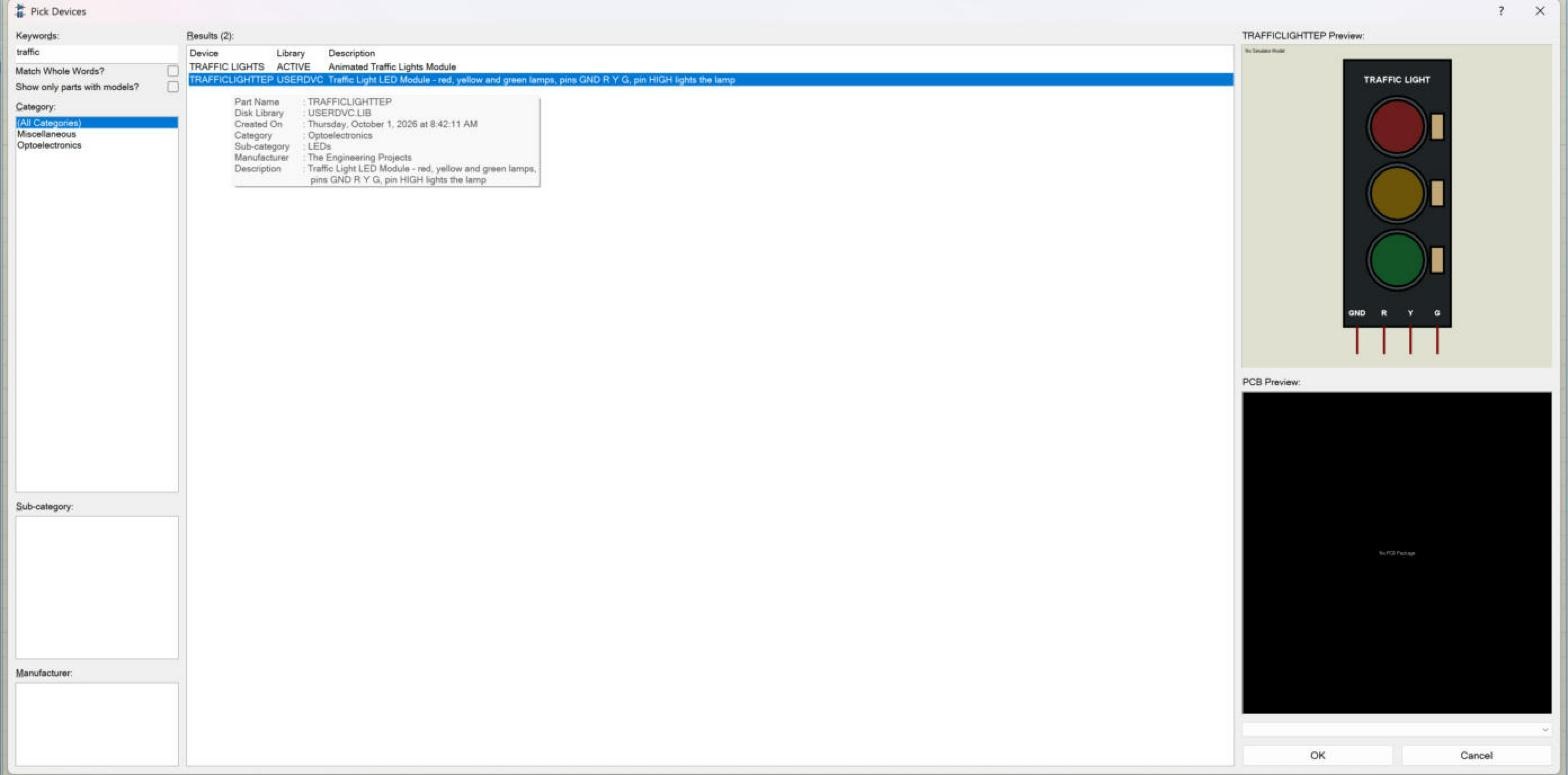
Everything here was done in Proteus 8.5 Professional on our PC, in the same project as the previous tutorials. The picture below shows the result we were working towards: our new part, TRAFFICLIGHTTEP, found by a keyword search in the Pick Devices dialogue, with its preview and its index data.
What Does Make Device Do?
Make Device is the command that turns tagged graphics and pins into a device, the Proteus word for a part type stored in a library. As we saw in the first tutorial of this series, a device holds the body graphics, the pins, the device properties such as the name and reference prefix, the packaging for PCB design, the default component properties, the data sheet and help links, and the index data that Pick Devices searches. Make Device collects all of these in one wizard and writes the result into a device library.
The help describes the procedure for a single-element part like ours in a few steps: place the graphics, place the pins, annotate the pins, tag everything, run Make Device, enter the name and prefix, optionally add a packaging, enter properties, link a data sheet, choose the library and click OK. We completed the first four steps in the earlier tutorials; today covers the rest.
How to Use Make Device in Proteus: Step by Step
Turning our drawing into a part takes four steps: tag it, run the five pages of the wizard, find the part in Pick Devices and place it.
Step 1: Tag the Whole Drawing
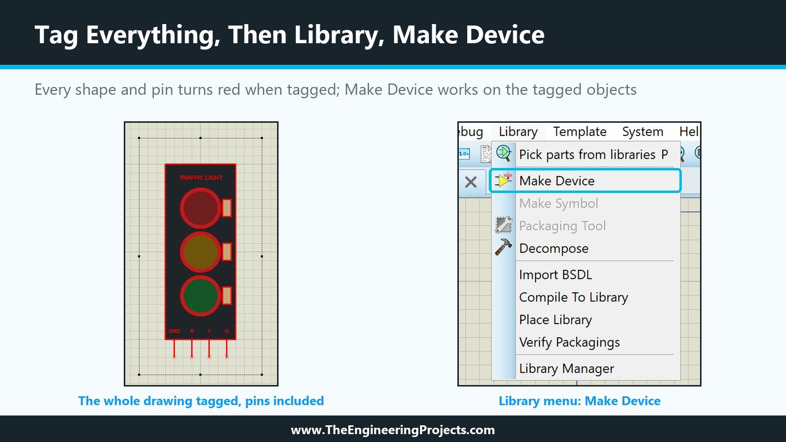
Make Device works on the tagged objects, and everything that belongs to the part must be tagged: the board, the rings, the lamps, the resistors, the title, the pin labels and the four pins. In selection mode, we dragged one large tag box from an empty spot above and to the left of the board to an empty spot below and to the right of the pin ends. Every object turned red, which shows it is tagged. A shape that is left untagged, for example a pin outside the box, is simply missing from the device.
Step 2: Open Library, Make Device
With everything tagged, choose Make Device from the Library menu, as in the right half of the picture above. Make Symbol is greyed out at this point; a symbol can hold only 2D graphics and markers, and our tagged objects include pins. The wizard has five pages, named at the top of each page: Device Properties, Packagings, Component Properties and Definitions, Device Data Sheet and Help File, and Indexing and Library Selection. The buttons at the bottom are Help, Back, Next, OK and Cancel; OK becomes active on the last page.
Page 1: Device Properties
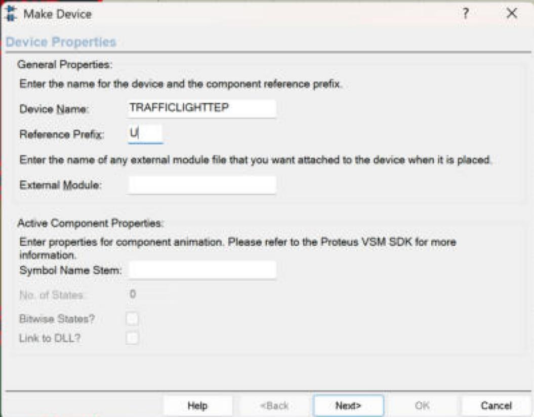
The first page has two sections.
- Device Name: the name of the part in the library. We chose TRAFFICLIGHTTEP: capitals without spaces, like the supplied parts, ending in TEP like the names of our other module libraries, such as HC12TEP. The name appears in Pick Devices, in the property script, and later in the link to the simulation model, so it is worth choosing once and keeping.
- Reference Prefix: the letters in front of the number of each placed component. We used U, so the first module on a sheet becomes U1. The help notes that an empty prefix creates components without a reference, with their value and properties hidden, which suits drawing aids but not real parts.
- External Module: a file attached to every placed component, used for reusable circuit blocks. An ordinary part leaves it empty, and so did we.
- Active Component Properties: Symbol Name Stem, No. of States, Bitwise States and Link to DLL. These are the animation settings we met in the first tutorial. The page itself points to the Proteus VSM SDK for details. We leave them empty today and come back to them in the animation tutorials, when the state symbols of our lamps exist.
Page 2: Packagings
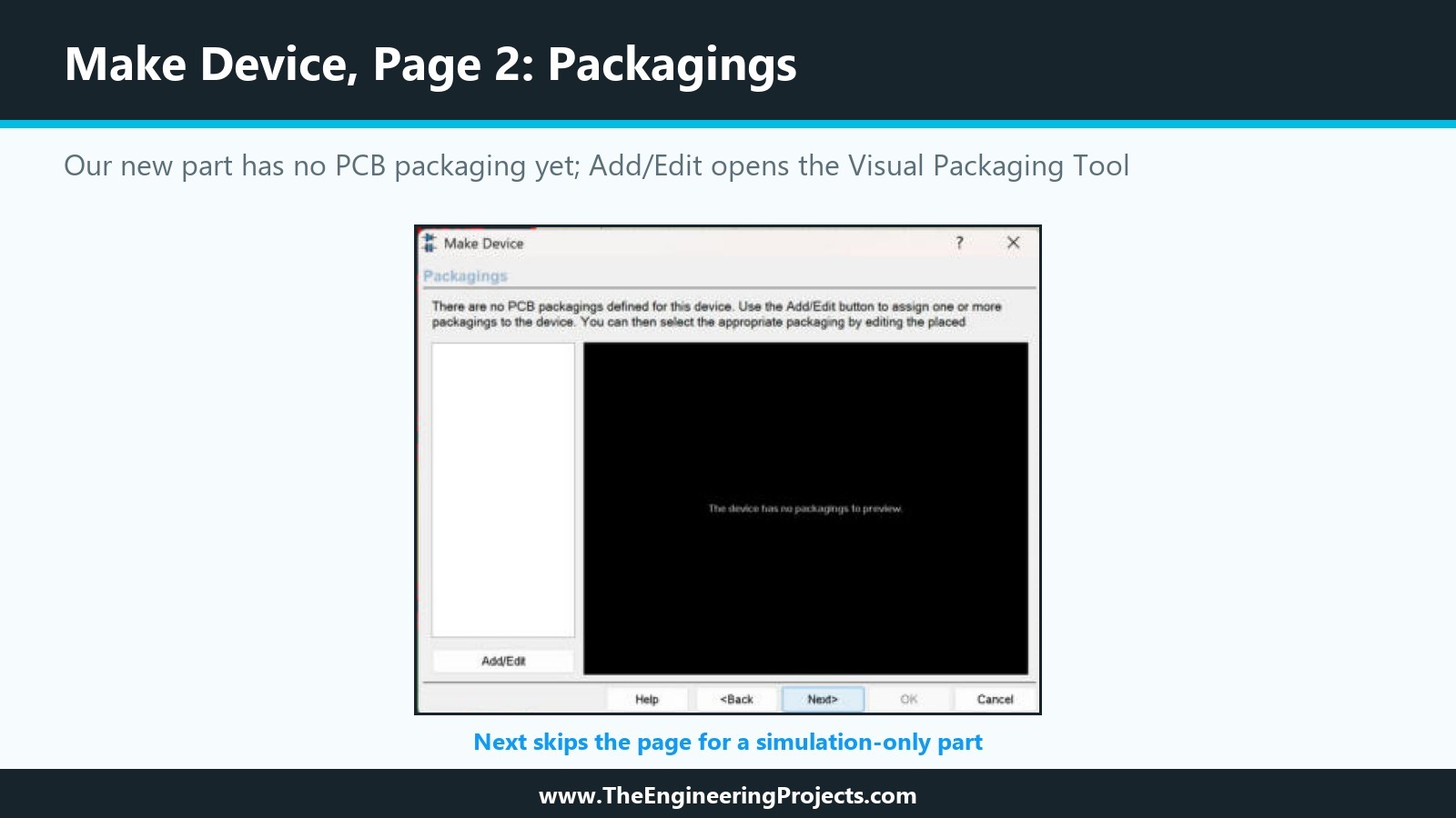
The second page lists the PCB packagings of the device. For our new part it said that there are no PCB packagings defined for this device, and the preview showed that the device has no packagings to preview. The Add/Edit button opens the Visual Packaging Tool, which links the part to a PCB footprint and maps pins to pads. A part used only for simulation does not need a packaging, so we clicked Next; packaging has its own tutorial later in the series.
Page 3: Component Properties and Definitions
The third page defines the properties that every placed component receives, for example the PRIMITIVE and MODDLL properties that link a simulation model, or a PACKAGE property for PCB work. It has a list of properties with New and Delete buttons and arrows to change their order, a Property Definition section (name, description and type) and a Property Defaults section (default value and visibility). For now we left the list empty; the next tutorial, How to Add Component Properties in Proteus, is entirely about this page.
Page 4: Device Data Sheet and Help File
The fourth page links a data sheet (a PDF) and a help file to the device. When a data sheet is set, a Data button appears in the Edit Component dialogue of placed parts. The help describes two places for data sheets: the data sheet folder of the Proteus installation, or a download server, for which the page has server, path, user and password fields. Our module has no data sheet of its own, so we left the page empty.
Page 5: Indexing and Library Selection
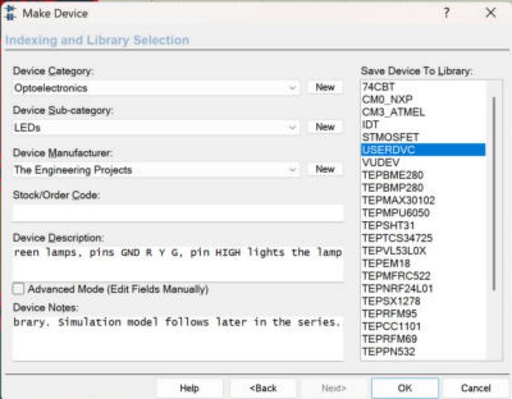
The last page decides how people will find the part and where it is stored.
- Device Category: a drop-down list of the existing categories, with a New button for your own. The list in Proteus 8.5 includes, among others, Analog ICs, Capacitors, Connectors, Diodes, Electromechanical, Microprocessor ICs, Miscellaneous, Optoelectronics, Peripherals, Resistors and Sensors. We chose Optoelectronics, where Proteus keeps its LEDs and displays.
- Device Sub-category: the sub-categories of the chosen category. For Optoelectronics they include 7-Segment Displays, Alphanumeric LCDs, Bargraph Displays, Dot Matrix Displays, Graphical LCDs, Lamps, LEDs and Optocouplers. We chose LEDs.
- Device Manufacturer: a long alphabetical list with a New button. "The Engineering Projects" was already there, because our module libraries use it, so we picked it.
- Stock/Order Code: a supplier code, which can be shown in the Bill of Materials; we left it empty.
- Device Description: the text shown in the results of Pick Devices and searched by keywords. We wrote "Traffic Light LED Module - red, yellow and green lamps, pins GND R Y G, pin HIGH lights the lamp", which contains the words people are likely to type.
- Device Notes: longer notes that can be read from the Edit Component dialogue. We noted that the part was made in this tutorial series and that its simulation model follows later.
- Save Device To Library: the list of device libraries that can be written to. Only read/write libraries appear here; Labcenter's own libraries are read-only and do not. On our PC, the list showed USERDVC and the libraries of our earlier TEP modules, among others. We chose USERDVC, the library Proteus provides for your own devices.
Then we clicked OK. There was no further question, because no component of this device existed in the design yet; when you remake a device that is already used in the open design, Proteus offers to update those components.
What Proteus Stored in the Library
After OK, USERDVC.LIB in the Proteus library folder had grown from 8032 to 11270 bytes, and its index file USERDVC.IDX from 44 to 197 bytes. The index now holds the category, sub-category, manufacturer and description of our part. The library holds the graphics and pins, and the text script below, which we read straight from the library file.
{*DEVICE}
{PREFIX=U}
{NOTES=Made in the TEP tutorial series How to Create a Proteus Library. Simulation model follows later in the series.}
{*INDEX}
{CAT=Optoelectronics}
{SUBCAT=LEDs}
{MFR=The Engineering Projects}
{DESC=Traffic Light LED Module - red, yellow and green lamps, pins GND R Y G, pin HIGH lights the lamp}
Compare it with the script of our HC-12 library that we looked at in the first tutorial. The structure is the same: a {*DEVICE} section with the prefix (and here our notes), and an {*INDEX} section with the category, sub-category, manufacturer and description. What is missing are the {*PROPDEFS} and {*COMPONENT} sections with the property definitions and default values, and the ACTIVE line with the animation settings. Our part has no properties and no animation yet; the next tutorials add them, and the script will grow accordingly.
Step 3: Find the Part in Pick Devices
A device is only useful if people can find it. We opened Pick Devices from the Library menu (P is its shortcut) and typed "traffic" into the Keywords field. Two parts appeared: our TRAFFICLIGHTTEP from USERDVC, and TRAFFIC LIGHTS from Proteus's own ACTIVE library, described as "Animated Traffic Lights Module". Proteus already has an animated traffic light; ours is different in that it reproduces the four-pin Arduino module, GND, R, Y and G, with its look and pin order, and it is the part we use to learn the whole process.
Selecting our part showed the drawing in the Schematic Preview, labelled "No Simulator Model", and the PCB Preview reported that there is no PCB package. A tooltip over the result listed the part name, the disk library USERDVC.LIB, the creation date, the category, sub-category, manufacturer and description, all as we had entered them.
How to Write a Description That Pick Devices Finds
The keyword search of Pick Devices follows a few rules described in the help, and they decide whether people find your part:
- Keywords are matched against the part name, the description, the category and the sub-category. A word that appears nowhere in these fields will never find the part.
- All keywords must match. The search is an AND search, so "traffic module" finds our part only because both words are in its description.
- Partial matches count unless Match Whole Words is ticked, so "traff" also finds it.
- Purely numeric keywords are matched against the digits in part names, which is how "7400" finds the 74LS00 and 74HC00.
- Wildcards * and ? compare against the part name.
So a good description names the part the way people call it ("Traffic Light LED Module"), lists what it has ("red, yellow and green lamps"), and includes the pin names or the main interface ("pins GND R Y G"). A short, precise description with the right words beats a long one.
Step 4: Place the Part on the Sheet
We clicked OK in Pick Devices, which added TRAFFICLIGHTTEP to the object selector, and placed it next to our original drawing. It appeared as U1 with the value TRAFFICLIGHTTEP above it: a real component, with the same look and the same four pins. While placing it, we noticed where the mouse held the part: at the wire end of the GND pin. That matches the help, which says that a device without an Origin marker takes the end of its top left pin as its origin; all our pin ends lie on the same line, and GND is the leftmost.
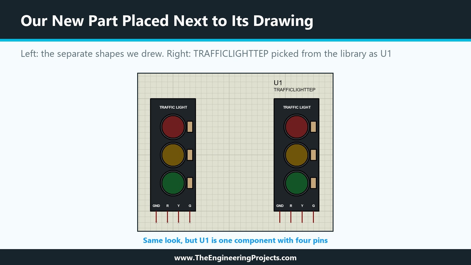
Two more details are worth knowing. First, Make Device did not change the drawing we had tagged: it is still made of separate shapes and pins, and it remains useful whenever we want to change the part and make it again. Second, the design now carries its own copy of the device, as every Proteus design does for the parts it uses. If we change the device in the library later, this copy changes only when we pick the part again.
How to Edit the Device Later
Parts are rarely perfect the first time. The help describes two routes, and we will use both in the coming tutorials:
- To change properties, place and tag a component of the device, run Make Device, click Next to the Component Properties page, edit, click Next twice and store it again with OK. There is no need to decompose it.
- To change graphics or pins, place a component, tag it and choose Decompose. The part breaks into its graphics, pins and a text script with its name, prefix, packaging and properties. Edit the pieces, tag them together with the script, and run Make Device; the tagged script brings the properties back without retyping.
Common Mistakes with Make Device in Proteus
| Problem | Cause | Solution |
|---|---|---|
| A shape or pin is missing from the part | It was not tagged | Tag everything with one tag box and check that all objects turn red |
| Your library is not in the Save Device To Library list | The library is read-only | Use USERDVC or create your own library with the Library Manager |
| Nobody finds the part in Pick Devices | Missing category or description | Fill in the indexing page with the words people search for |
| Placed parts have no reference such as U1 | The reference prefix was left empty | Enter a prefix such as U |
| A changed device does not change an existing design | The design keeps its own copy of the part | Pick the part again in that design to update it |
| The part lands off the grid when placed | Its origin is a pin end or point off the grid | Keep pin ends on the 100 thou grid, or add an Origin marker |
In the Next Tutorial
Our Traffic Light Module is now a real Proteus part in USERDVC, but it has no properties yet. In the next tutorial, How to Add Component Properties in Proteus, we will open the Component Properties and Definitions page again, add property definitions with types, descriptions, defaults and visibility, and see how they appear in the Edit Component dialogue of a placed part.
FAQ
How do I create a new device in Proteus?
Draw the body with the 2D graphics tools, place and annotate the pins, tag everything and choose Library, Make Device. Enter the name and prefix, go through the packaging, properties and data sheet pages, choose the category and a writable library such as USERDVC, and click OK.
Where does Proteus save a device made with Make Device?
In the device library you select on the last page of the wizard, for example USERDVC.LIB in the Proteus library folder. The index data goes into the matching .IDX file.
Why can I not save my device into a Proteus library?
Only read/write libraries appear in the list. Labcenter's own libraries are read-only; use USERDVC or a library of your own.
What is the reference prefix in Proteus?
The letters in front of the number of each placed component, such as U in U1 or R in R1. It also groups similar parts in the Bill of Materials.
Do I need a PCB package to make a device in Proteus?
No. The Packagings page can be skipped; a package can be added later with the Visual Packaging Tool.
How do I find my new part in Proteus?
Open Pick Devices (Library menu or the P key) and type a word from its name or description, or browse its category and sub-category.
That is all for today. Our Traffic Light Module is now a real library part that anyone can pick and place. If you have any questions, ask in the comments. Take care.