Hello friends, I hope you all are doing great. Today, I am going to share the new INA219 Current Sensor Library for Proteus V1.0. The INA219 measures the current, the voltage and the power of a circuit at the same time, and sends all three to the Arduino over I2C. It is the sensor behind battery monitors, solar chargers, USB power meters and robots that know how much their motors draw. Now you can build and test those projects in Proteus, with the purple GY-219 module and a DC electronic load to measure.
Behind the parts sit our own models, not a part that shows a number. The module's 0.1 ohm shunt is a real resistor in the analog simulation of Proteus, so the current of your circuit really flows through it. The INA219 measures the voltage across it and the voltage after it, does its own calibration maths, and answers the Arduino from its six registers exactly as the datasheet says, with the real ranges that clip and the real overflow flag. You get three devices: the GY-219 as a Simple device with a live STATUS panel and as an Advance device with a pop-up window and three test tools, and the DC load with its own panel. The demo runs the Adafruit INA219 library on our Arduino UNO V4.0.
NOTICE: a current sensor is easy to fake: read a number from a property and hand it to the Arduino. We wanted more. Our shunt is part of the circuit, our INA219 measures it, converts it and answers the I2C bus register by register, so the Adafruit library reads it exactly as on your desk, and the classic mistakes fail exactly as they do there. It took our team a lot of hard work. Your feedback is the fuel that keeps us going, so please tell us what you think in the comments below or in the INA219 board of our forum. And if our free libraries help you, you can buy us a coffee. So, let's get started with the INA219 Current Sensor Library for Proteus V1.0:
What is the INA219?
The INA219 from Texas Instruments is a high-side current and power monitor with an I2C interface. It sits next to a small shunt resistor placed between the supply and the load. It measures the tiny voltage across the shunt, which is proportional to the current (What is Ohm's Law?), and the bus voltage on the load's side, and multiplies the two into the power. The GY-219 module carries the chip, a 0.1 ohm shunt, two pull-up resistors, the A0 and A1 address jumpers, a screw terminal for VIN+ and VIN- and a header for VCC, GND, SCL and SDA. For the module's pinout, read our INA219 Current Sensor Module: Datasheet, Pinout and Features.
| INA219 on the GY-219 | |
|---|---|
| Shunt voltage | +-40, 80, 160 or 320 mV (PGA), 10 uV a step |
| Bus voltage | 0 to 16 or 32 V range (26 V maximum), 4 mV a step |
| Current | +-3.2 A on the 0.1 ohm shunt (PGA /8) |
| ADC | 9 to 12 bits (84 to 532 us) or 2 to 128 samples averaged |
| Registers | six, 16 bits: Configuration, Shunt, Bus, Power, Current, Calibration |
| Interface | I2C at 0x40 (0x41, 0x44, 0x45 with the jumpers) |
| Supply | VCC 3.0 to 5.5 V |
| Devices | INA219TEP (Simple), INA219ADVTEP (Advance), DCLOADTEP (the load) |
High-Side Measurement
The shunt goes in the positive wire: the supply's + to VIN+, VIN- to the load's +, and the grounds of the supply, the load and the Arduino together. With 800 mA through the 0.1 ohm shunt, VIN+ and VIN- are only 80 mV apart, so the load still gets almost the whole supply voltage. That is why the INA219 can measure the current and the voltage of the same wire. Our older Current Sensor Library for Proteus with the ACS712 measures current with a Hall sensor instead; the INA219 adds the voltage and the power and talks I2C.
The Calibration
The INA219 can turn the shunt voltage into amperes and watts by itself, but it has to know the shunt. That is the Calibration register: Current = Shunt x Cal / 4096 and Power = Current x Bus / 5000. Both registers stay 0 until the calibration is written. The Adafruit library offers three: setCalibration_32V_2A() (the default, 0.1 mA a step), setCalibration_32V_1A() (0.04 mA a step) and setCalibration_16V_400mA() (0.05 mA a step, a +-40 mV PGA). Each one is a trade between resolution and range, and choosing the wrong one is the most common INA219 mistake, as you will see below.
Registers and Conversions
Every access starts with the register pointer: a write of one byte sets it, a write of three bytes also writes that register, MSB first; a read returns the register the pointer points at. The Configuration register (power-on 0x399F) sets the bus range, the PGA, the ADC's resolution or averaging and the mode. In the default mode the chip converts the shunt and the bus again and again, about once a millisecond, and sets the CNVR bit in the Bus Voltage register after each cycle; OVF next to it says the current or power maths overflowed.
What's New in INA219 Current Sensor Library for Proteus V1.0
- Real parts: the purple GY-219 module drawn at about three times its real size, and a DC electronic load module with its heatsink, display and knob.
- Two styles: a Simple device with a STATUS panel and an Advance device with a pop-up window; the LEDs and the panel button sit on the board itself.
- A real shunt: the 0.1 ohm resistor between VIN+ and VIN- is part of the analog simulation; the INA219 reads the shunt and bus voltages from it.
- The real chip: six registers over I2C, the power-on values, the calibration maths, the PGA and bus ranges that clip, CNVR and OVF, the conversion times and averaging, power-down and triggered modes.
- A DC load: 0 to 4 A with - and + buttons, six presets from an LED to a heater and an ON / OFF switch, on its own panel or in the INA219's pop-up.
- Mistake detection: no calibration, a current over the PGA's range, OVF, a bus over the range, swapped wires, a register that is not there.
- Three test tools on the Advance device: I2C, Readings, and Calibration and ranges.
- A two-node demo on our Arduino UNO V4.0 with the Adafruit library: a 12 V motor at 800 mA on node 1 and a 5 V servo at 250 mA on node 2.
- A compact package: about 1.27 MB, without the C++ source code of the model.
Three Devices: the Module and the Load
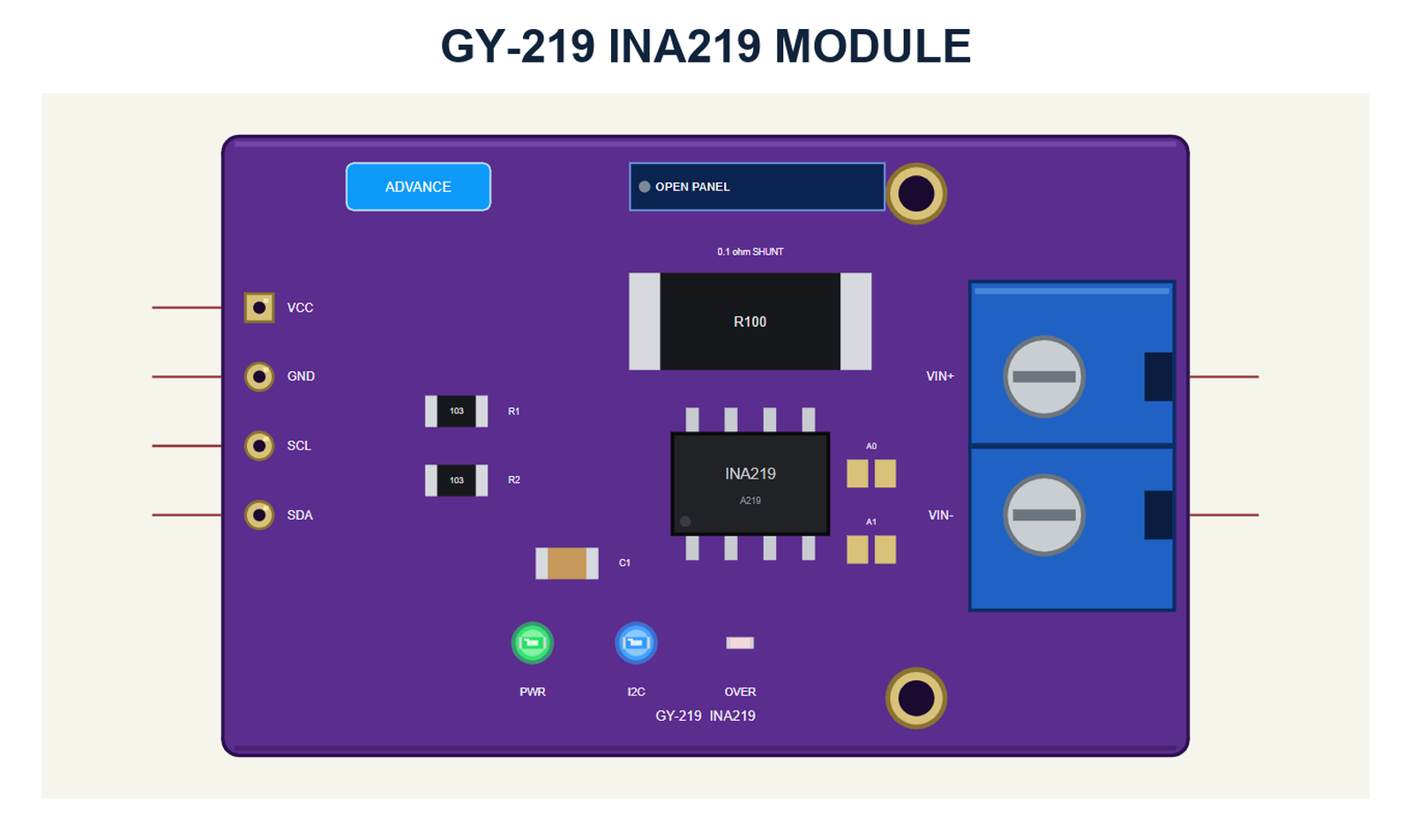
The module looks like the one in your kit: the purple board with the INA219 in its SOIC-8 package, the big black R100 shunt (0.1 ohm), the pull-ups R1 and R2, the capacitor C1, the A0 and A1 jumpers, the header VCC, GND, SCL and SDA on the left and the blue screw terminal VIN+ and VIN- on the right, facing the load.
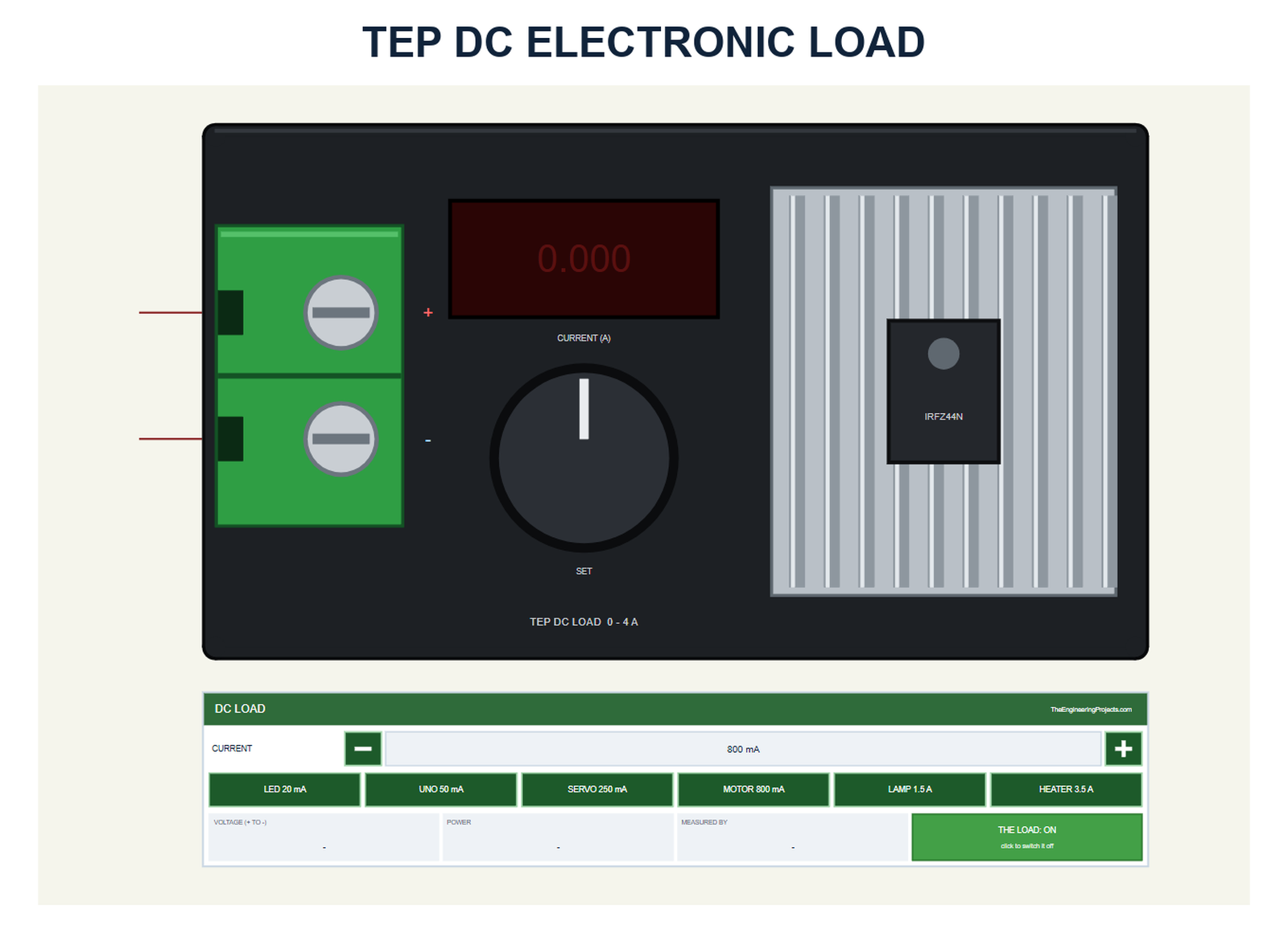
The DC load draws a set current, from 0 to 4 A, from whatever feeds it, like the adjustable constant-current loads used to test power supplies. Its display shows the current it really draws, and its DC LOAD panel has - and + (10 mA a click), six presets (LED 20 mA, UNO 50 mA, SERVO 250 mA, MOTOR 800 mA, LAMP 1.5 A, HEATER 3.5 A), the readouts VOLTAGE, POWER and MEASURED BY, and the ON / OFF switch.
| Simple | Advance | |
|---|---|---|
| Device | INA219TEP | INA219ADVTEP |
| On the schematic | The module and the STATUS panel | The module |
| The load | On the DC load's panel | The same, and in the pop-up |
| Status | Banner, 10 readouts, the last 4 events | A pop-up: Sensor, Event log, Tests |
| Interaction | The red X, PANEL on the board | The pop-up, OPEN PANEL on the board |
Download INA219 Current Sensor Library for Proteus
Click the button below to download INA219-Current-Sensor-Library-for-Proteus-v1.0.zip (about 1.27 MB, without the C++ source code of the model):
INA219 Current Sensor Library for Proteus V1.0: GY-219 Power Monitor- README.txt: the devices, installation, the demo, wiring, the test tools and real hardware.
- Proteus Library Files:
TEPINA219.LIBandArduinoV4TEP.LIBfrom our Arduino Library for Proteus V4.0. - Proteus Model Files:
TEPINA219.DLLandTEPARDUINO.DLL. - Proteus Simulation:
INA219-Current-Sensor-ArduinoUnoV4.pdsprj,INA219_Demo.hexand copies of the two DLLs. - Arduino Code:
INA219_Demo.ino. It needs the Adafruit INA219 library from the Library Manager of the Arduino IDE, only if you want to change the sketch.
No Proteus yet? Read How to Download and Install Proteus 7 and 8. New to libraries? Follow How to Install a New Library in Proteus.
How to Install INA219 Current Sensor Library for Proteus
- Close Proteus and extract the whole zip file, for example to your Desktop.
- Copy the two files from Proteus Library Files into the LIBRARY folder of Proteus (usually
C:\Program Files (x86)\Labcenter Electronics\Proteus 8 Professional\LIBRARY). - Copy
TEPINA219.DLLandTEPARDUINO.DLLfrom Proteus Model Files into the MODELS folder. - Delete
TEPINA219.IDXfrom the LIBRARY folder if it is there. - Start Proteus, press P and search for INA219 or DCLOAD.
Tip: keep the Proteus Simulation folder together, because the project needs its .hex file and the DLLs beside it. The library is tested in Proteus 8.5; Proteus 7 is not supported.
The INA219 Parts in Proteus
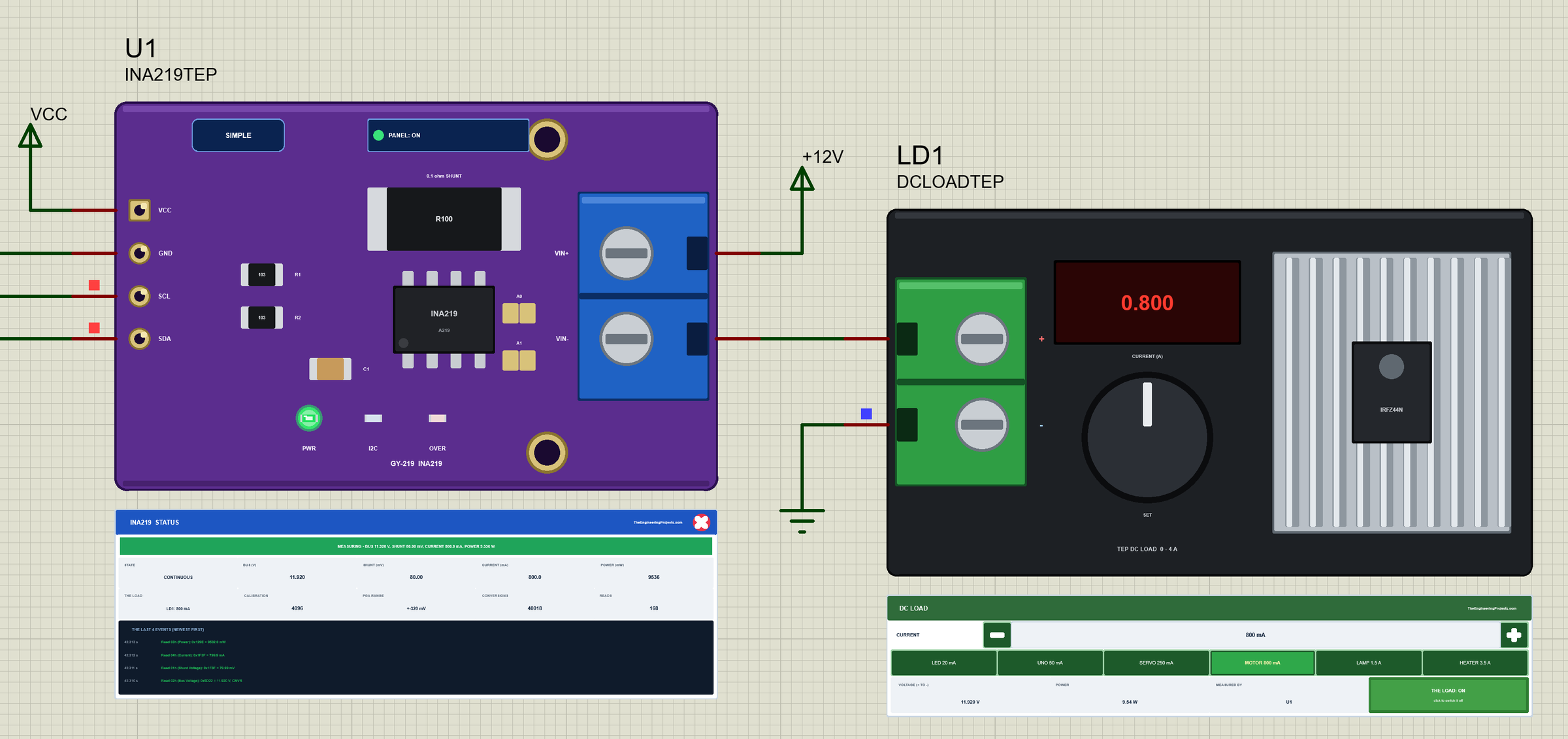
Three LEDs sit on the module's board: PWR while VCC is there, I2C, which flashes when the Arduino talks to the INA219, and OVER, which lights when a range clips or the maths overflows. Next to the SIMPLE or ADVANCE badge is the panel button. The LEDs, the badge, the button and the panels are TEP additions; the real module has none of them.
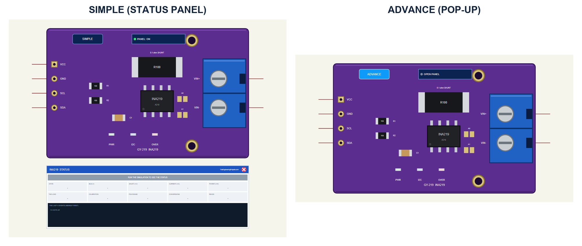
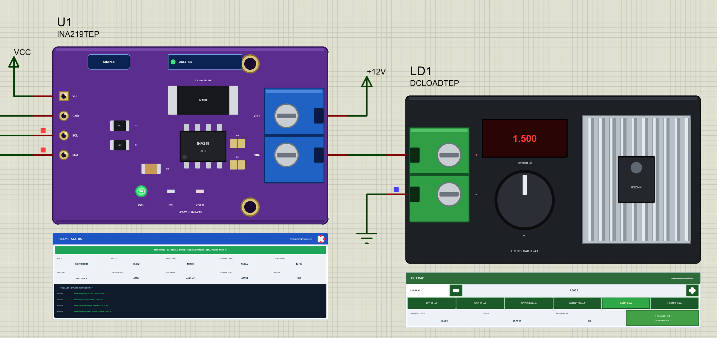
The Simple device adds the STATUS panel. Its banner says what the registers hold, for example "MEASURING - BUS 11.920 V, SHUNT 80.00 mV, CURRENT 800.1 mA, POWER 9.536 W", and turns orange or red when something clips or a warning comes. Ten readouts follow: the state, the bus voltage, the shunt voltage, the current, the power, the load on VIN-, the calibration, the PGA range, the conversions and the reads. At the bottom are the last four events.
The red X closes the STATUS panel, and the PANEL button on the board opens it again, so a big project stays readable:
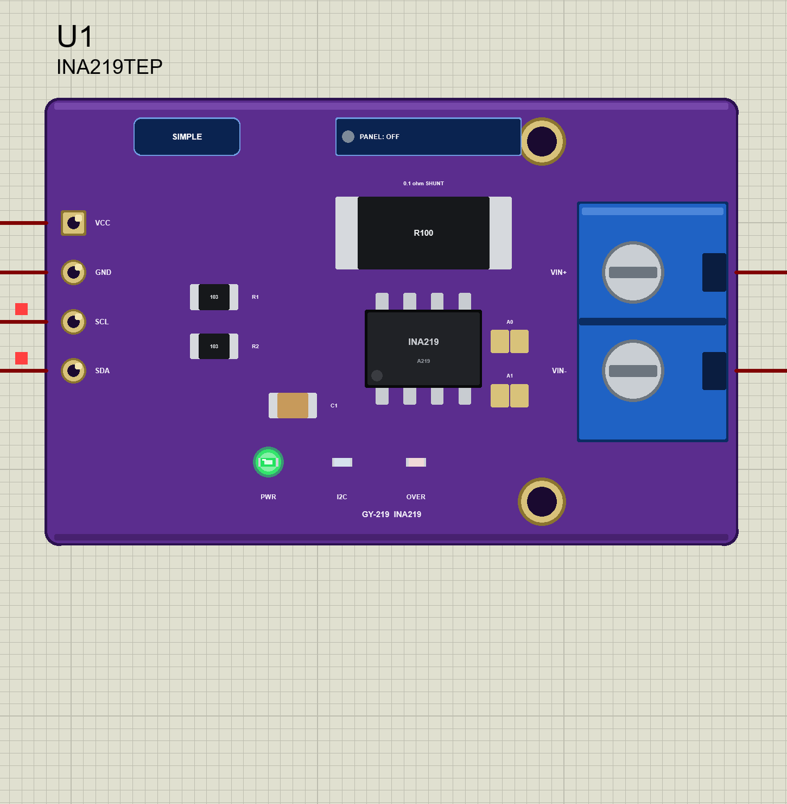
The Advance device keeps the schematic clean: only the module. Its live data opens in a pop-up window at Run, and the OPEN PANEL button on the board brings the window back if you close it. The module has two properties: ADDRESS (0x40, 0x41, 0x44 or 0x45, the jumpers) and NOISE (10 uV by default, one step of the shunt register). The load has CURRENT and LOAD (ON or OFF) for the start.
The Demo Circuit
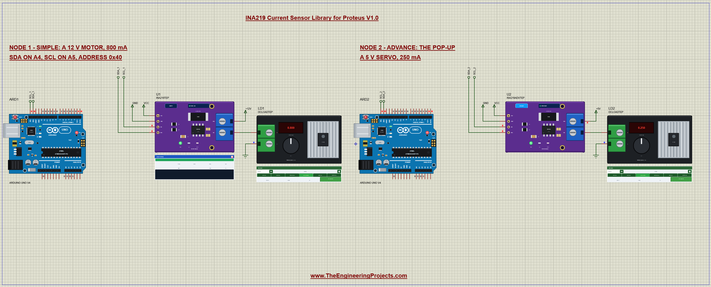
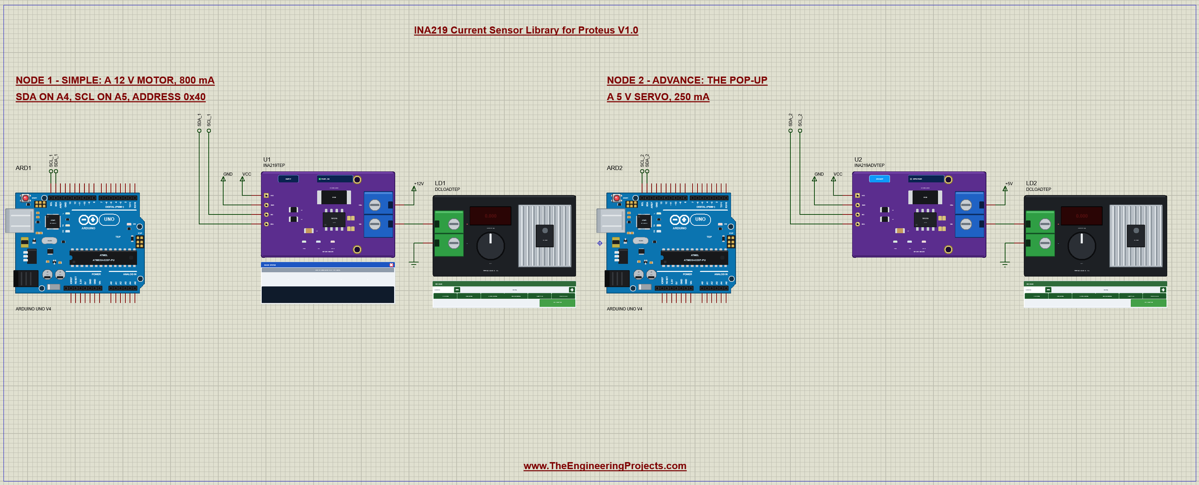
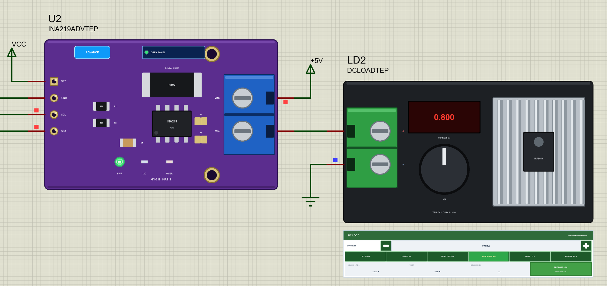
The demo project has two nodes. Each one is an Arduino UNO V4.0 from our Arduino UNO Library for Proteus V4.0 with a GY-219 on its SDA and SCL pins, which are A4 and A5, and a DC load fed through the module's shunt. Both UNOs run the same INA219_Demo.hex. Node 1 uses the Simple GY-219 on a +12V supply with the load at 800 mA, like a 12 V motor; node 2 uses the Advance GY-219 on +5V with the load at 250 mA, like a small servo.
Wiring
| GY-219 | Connects to |
|---|---|
| VCC | the UNO's 5V (3.3 V works too) |
| GND | GND (shared by the UNO, the supply and the load) |
| SCL | A5 (the SCL pin) |
| SDA | A4 (the SDA pin) |
| VIN+ | the supply's + |
| VIN- | the load's + |
In Proteus, SDA and SCL reach their UNO through net labels, SDA_1 and SCL_1 for node 1 and SDA_2 and SCL_2 for node 2. VIN+ goes to a +12V or +5V power terminal, VIN- straight into the load's +, and the load's - to ground. The Wire library turns on the UNO's internal pull-ups, which hold the I2C bus HIGH in the simulation. The serial monitor needs no wires at all, because it is built into the UNO V4.0.
The Arduino Code
The demo sketch uses the Adafruit INA219 library (version 1.2.3) with Adafruit BusIO. New to Arduino? Start with Arduino Tutorial for Beginners and Introduction to Arduino UNO. The sketch begins with Wire and the library, and the sensor object at its address:
#include <Wire.h>
#include <Adafruit_INA219.h>

const uint8_t INA_ADDR = 0x40;                 // the INA219's I2C address (A0 / A1 open)

Adafruit_INA219 ina219(INA_ADDR);
In setup(), begin() checks that the INA219 answers and calls setCalibration_32V_2A(), the 32 V range with 0.1 mA a step:
  if (!ina219.begin()) Serial.println(F("INA219 not found - check the wiring"));
  else Serial.println(F("CAL: 32 V, 2 A (0.1 mA a step)"));   // begin() calls setCalibration_32V_2A()
A reading is four calls, one per register: the bus voltage, the shunt voltage, the current and the power. The sketch also adds up the energy, the power multiplied by the time since the last reading:
void readAll() {
  const float bus = ina219.getBusVoltage_V();
  const float shunt = ina219.getShuntVoltage_mV();
  const float current = ina219.getCurrent_mA();
  const float power = ina219.getPower_mW();
  const unsigned long now = millis();
  if (lastAt) energy_mWh += power * (now - lastAt) / 3600000.0;   // mW x hours
  lastAt = now;
  Serial.print('#'); Serial.print(++count);
  Serial.print(F("  Bus ")); Serial.print(bus, 3);
  Serial.print(F(" V  Shunt ")); Serial.print(shunt, 2);
  Serial.print(F(" mV  Current ")); Serial.print(current, 1);
  Serial.print(F(" mA  Power ")); Serial.print(power, 0);
  Serial.print(F(" mW  Energy ")); Serial.print(energy_mWh, 2); Serial.println(F(" mWh"));
}

// the six registers by hand: the pointer, then 2 bytes MSB first
CAL 2A, CAL 1A and CAL 400mA switch between the library's three calibrations, and SLEEP and WAKE call powerSave(). The commands are compared without caring about upper or lower case:
  else if (!strcasecmp(s, "CAL 2A")) { ina219.setCalibration_32V_2A(); Serial.println(F("CAL: 32 V, 2 A (0.1 mA a step)")); }
  else if (!strcasecmp(s, "CAL 1A")) { ina219.setCalibration_32V_1A(); Serial.println(F("CAL: 32 V, 1 A (0.04 mA a step)")); }
  else if (!strcasecmp(s, "CAL 400mA")) { ina219.setCalibration_16V_400mA(); Serial.println(F("CAL: 16 V, 400 mA (0.05 mA a step)")); }
  else if (!strcasecmp(s, "SLEEP")) { ina219.powerSave(true); Serial.println(F("SLEEP: the INA219 powers down")); }
  else if (!strcasecmp(s, "WAKE")) { ina219.powerSave(false); Serial.println(F("WAKE: converting again")); }
RAW reads the six registers by hand with Wire: the pointer first, then two bytes, MSB first:
uint16_t readRegister(uint8_t reg) {
  Wire.beginTransmission(INA_ADDR);
  Wire.write(reg);
  Wire.endTransmission();
  Wire.requestFrom(INA_ADDR, (uint8_t)2);
  const uint8_t msb = Wire.read(), lsb = Wire.read();
  return (uint16_t)msb << 8 | lsb;
}
The HEX file is in the package, so you do not need the Arduino IDE to run the demo. To change the sketch, install "Adafruit INA219" from the Library Manager, open the sketch in the Arduino IDE and export the compiled binary, as in How to get the HEX file from Arduino. It needs 13,858 bytes of flash and 557 bytes of RAM.
The Serial Monitor
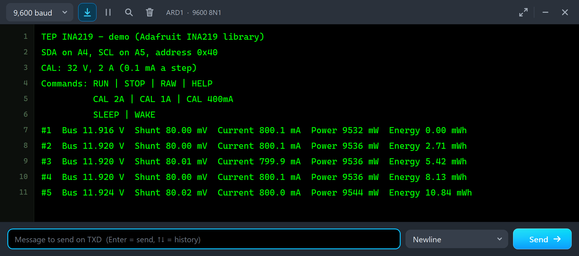
Both UNOs have the serial monitor built in, and it opens at Run. The screenshots use its Simple interface. Node 1 starts like this:
TEP INA219 - demo (Adafruit INA219 library)
SDA on A4, SCL on A5, address 0x40
CAL: 32 V, 2 A (0.1 mA a step)
Commands: RUN | STOP | RAW | HELP
          CAL 2A | CAL 1A | CAL 400mA
          SLEEP | WAKE
#1  Bus 11.916 V  Shunt 80.00 mV  Current 800.1 mA  Power 9532 mW  Energy 0.00 mWh
#2  Bus 11.920 V  Shunt 80.00 mV  Current 800.1 mA  Power 9536 mW  Energy 2.71 mWh
#3  Bus 11.920 V  Shunt 80.01 mV  Current 799.9 mA  Power 9536 mW  Energy 5.42 mWh
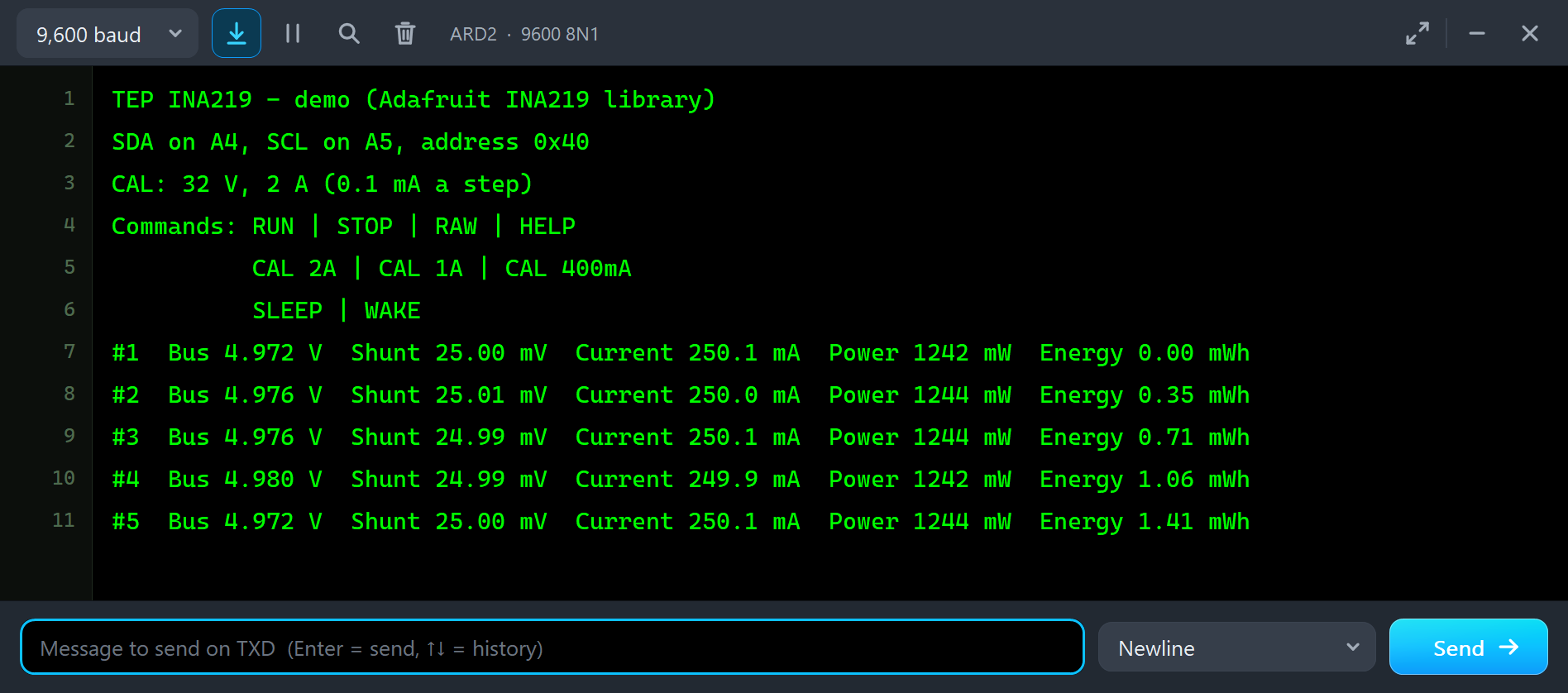
Everything follows from the circuit: 800 mA through 0.1 ohm is 80 mV across the shunt, so the bus after the shunt is 12 - 0.08 = 11.92 V, and the power is 11.92 V x 0.8 A = 9.536 W. The INA219 computed the current and the power itself: 8000 shunt steps x 4096 / 4096 = 8000 current steps of 0.1 mA, and 8000 x 2980 / 5000 = 4768 power steps of 2 mW. The energy grows by about 2.7 mWh a second. Node 2 shows the 5 V servo:
#1  Bus 4.972 V  Shunt 25.00 mV  Current 250.1 mA  Power 1242 mW  Energy 0.00 mWh
#2  Bus 4.976 V  Shunt 25.01 mV  Current 250.0 mA  Power 1244 mW  Energy 0.35 mWh
Type a command in the monitor and press Enter: STOP stops the readings, RUN starts them again, and the others are explained below. HELP lists them all.
Change the Load
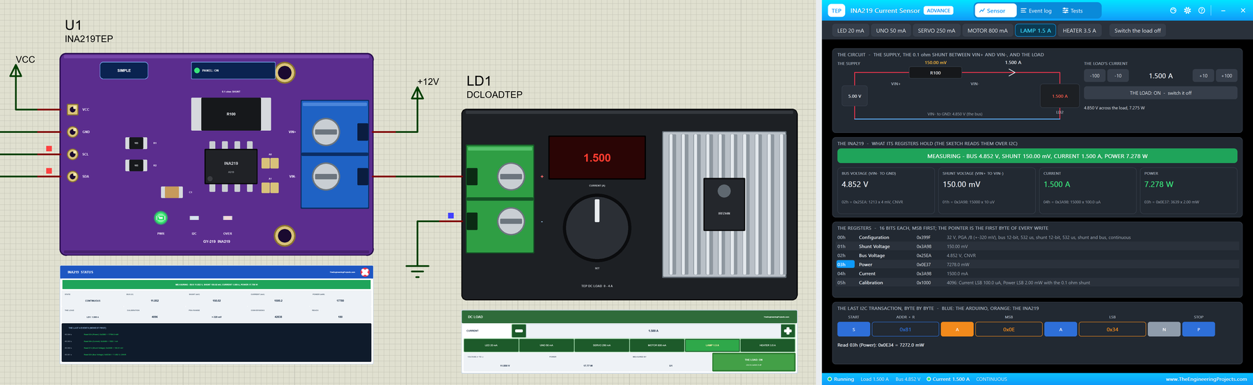
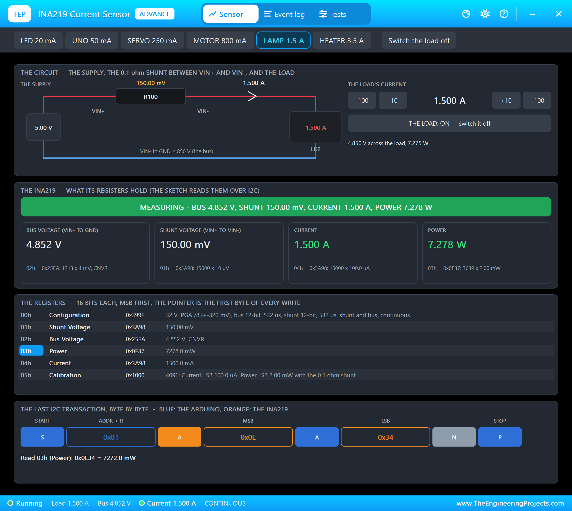
Now let's ask for more current while the simulation runs. We clicked LAMP 1.5 A on LD1's DC LOAD panel with the mouse:
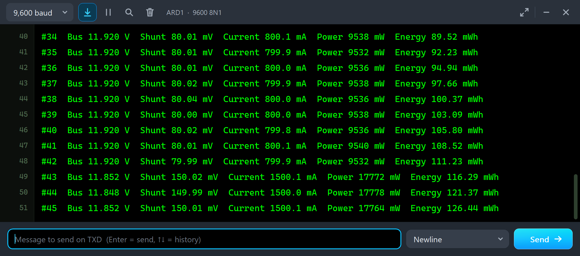
#42  Bus 11.920 V  Shunt 79.99 mV  Current 799.9 mA  Power 9532 mW  Energy 111.23 mWh
#43  Bus 11.852 V  Shunt 150.02 mV  Current 1500.1 mA  Power 17772 mW  Energy 116.29 mWh
#44  Bus 11.848 V  Shunt 149.99 mV  Current 1500.0 mA  Power 17778 mW  Energy 121.37 mWh
The shunt now drops 150 mV, so the bus falls to 11.85 V, and the power is 17.77 W. The energy line grows faster. Note that the reading follows within one line: the INA219 converts about once a millisecond, far faster than the sketch reads.
The Calibration and the Ranges
The most common INA219 mistake is a calibration made for a smaller current. We typed CAL 400mA on node 1, with the lamp still drawing 1.5 A:
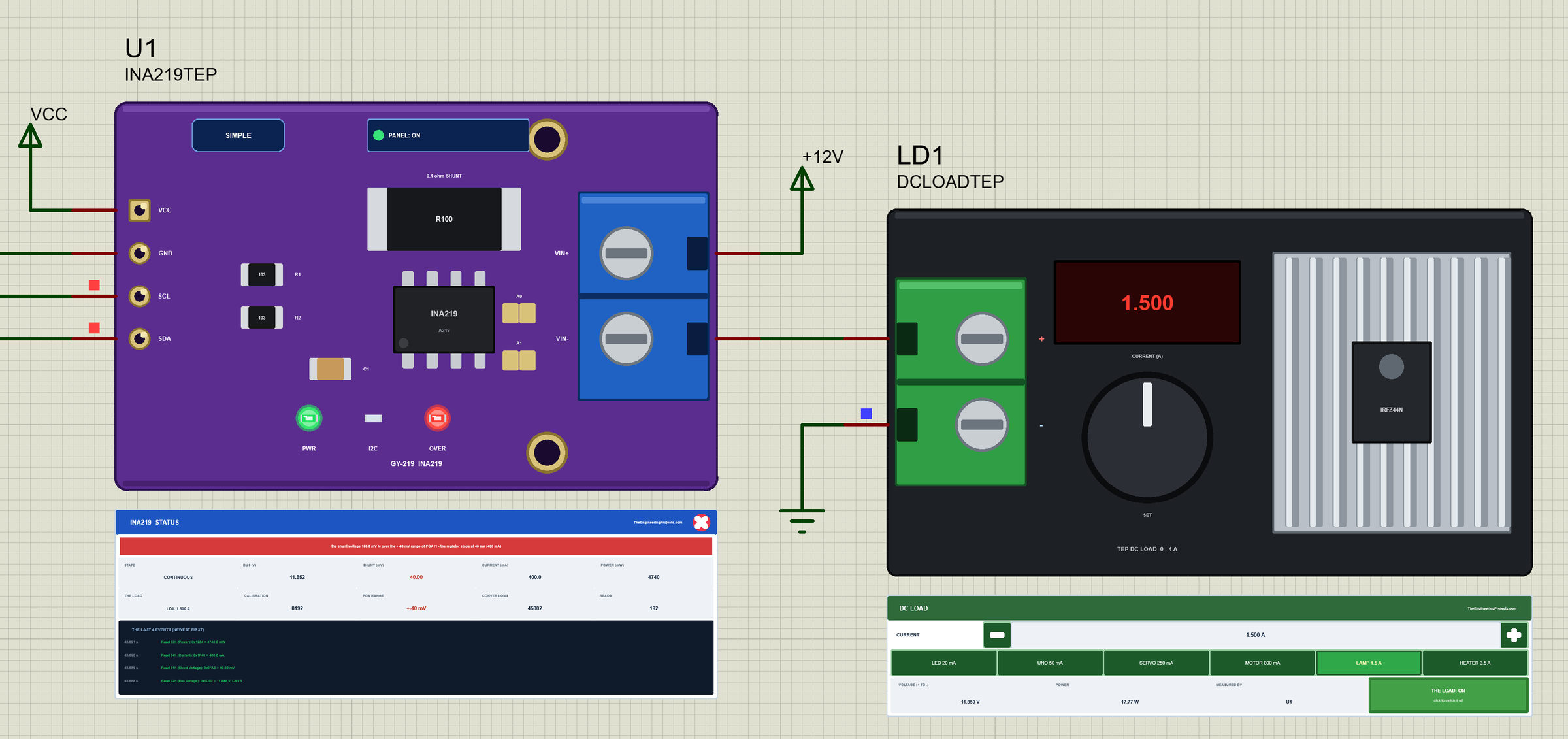
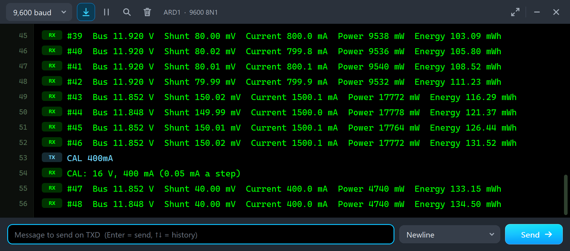
#46  Bus 11.852 V  Shunt 150.02 mV  Current 1500.1 mA  Power 17772 mW  Energy 131.52 mWh
CAL 400mA
CAL: 16 V, 400 mA (0.05 mA a step)
#47  Bus 11.852 V  Shunt 40.00 mV  Current 400.0 mA  Power 4740 mW  Energy 133.15 mWh
#48  Bus 11.848 V  Shunt 40.00 mV  Current 400.0 mA  Power 4740 mW  Energy 134.50 mWh
setCalibration_16V_400mA() sets the PGA to /1, a range of +-40 mV. The shunt really drops 150 mV, but the register stops at 40.00 mV, and 40 mV across 0.1 ohm is exactly 400.0 mA. A current that sticks at a round number is always a range. The sketch still prints it as if it were true, so choose the calibration for the largest current your circuit can draw.
The Load Off
Back on CAL 2A, we clicked the load's switch on its panel:
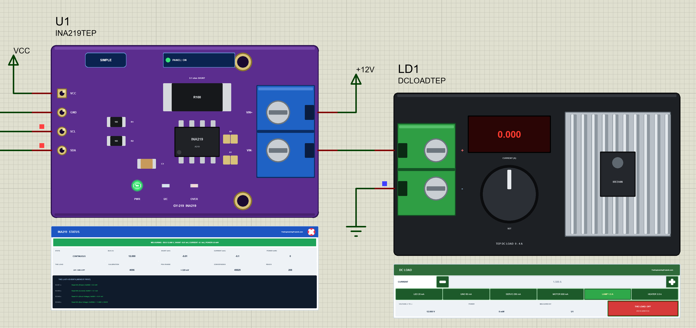
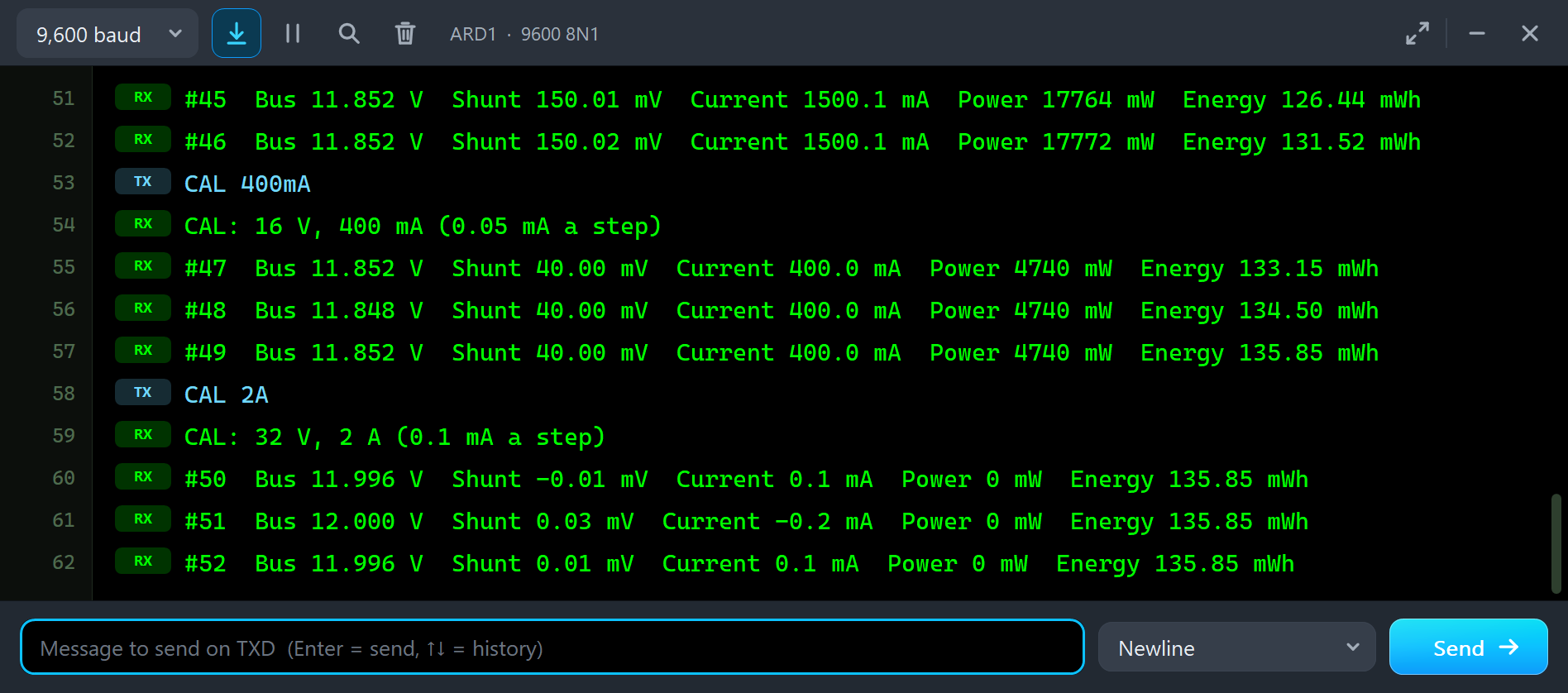
CAL 2A
CAL: 32 V, 2 A (0.1 mA a step)
#50  Bus 11.996 V  Shunt -0.01 mV  Current 0.1 mA  Power 0 mW  Energy 135.85 mWh
#51  Bus 12.000 V  Shunt 0.03 mV  Current -0.2 mA  Power 0 mW  Energy 135.85 mWh
With no current there is no drop across the shunt, so the bus reads the whole 12.000 V. The current reads 0.1 or -0.2 mA: one step of noise either way, as a real INA219 shows.
The Advance Pop-Up Window
At Run, the Advance GY-219 opens its own window, INA219 Current Sensor, with the look of our TEP Serial Monitor Advance for Proteus. It has three tabs, Sensor, Event log and Tests, plus Settings and Help behind the gear and question mark icons. The status bar at the bottom always shows the load, the bus, the current and the state.
The Sensor Page
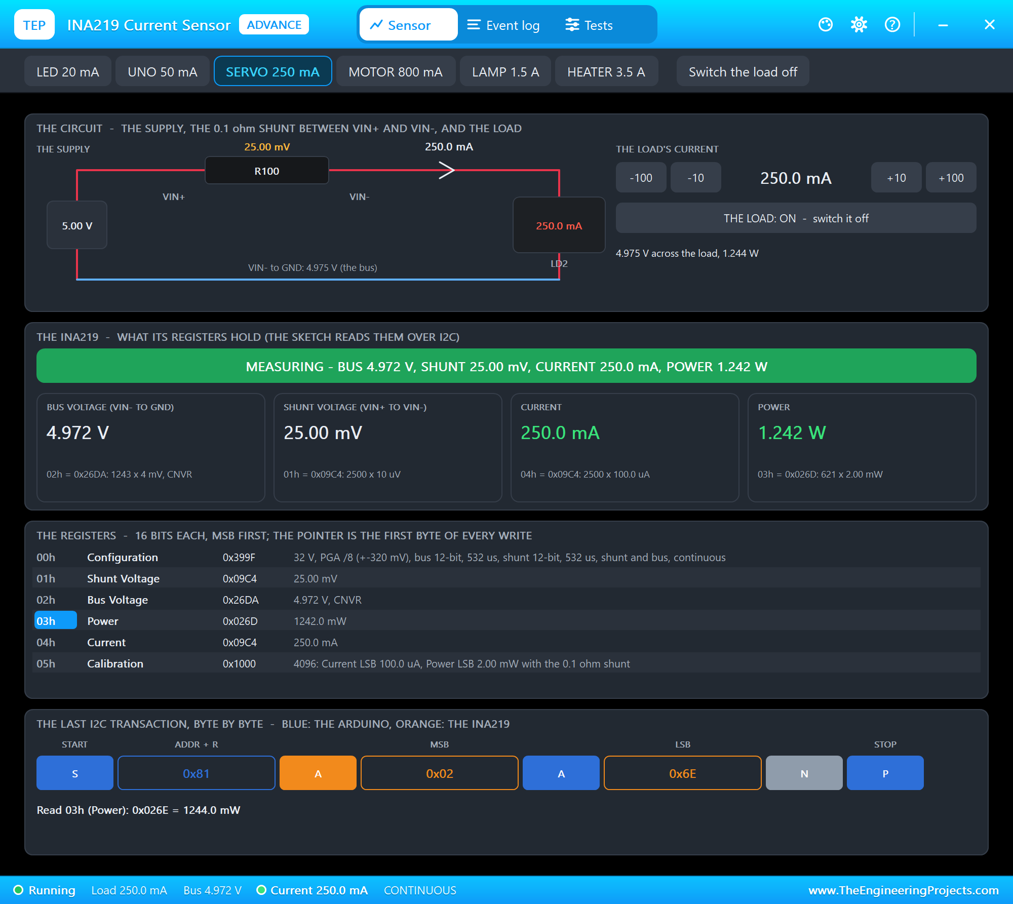
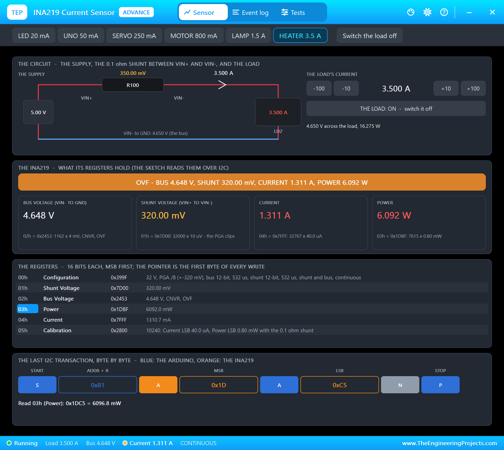
The toolbar carries the load's six presets and its switch. The top card is the circuit: the supply, the R100 shunt with its voltage, the current, the load and the bus voltage, and on the right the load's current with -100, -10, +10 and +100 mA. The next card is the INA219: the banner and the bus voltage, the shunt voltage, the current and the power as its registers hold them, each with the raw word. The registers card decodes all six, with the pointer marked; the last card draws the last I2C transaction byte by byte. We clicked LAMP 1.5 A:
The Calibration on Node 2
We typed CAL 400mA on node 2 as well, and opened Calibration and ranges on the Tests tab:
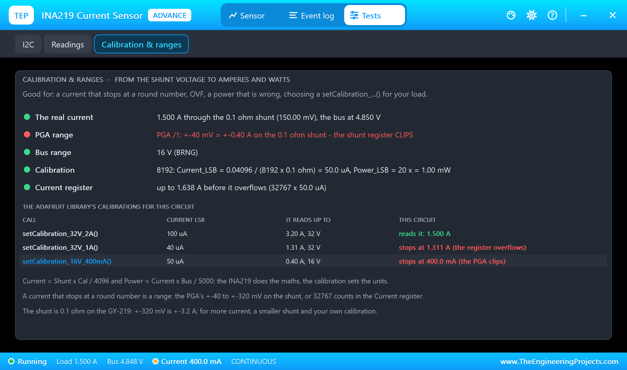
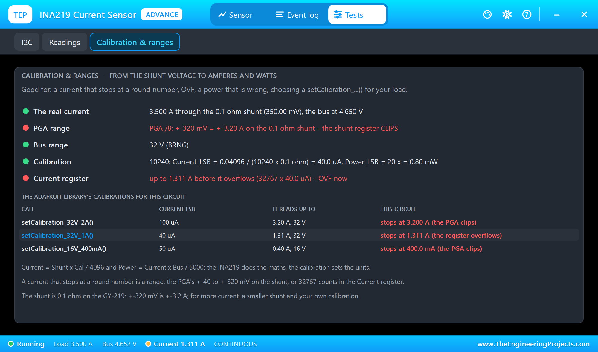
It shows the real current through the shunt, the PGA's range against it, the bus range, the calibration with its Current_LSB worked out, and where the Current register overflows. The table below compares the Adafruit library's three calibrations with this very circuit: which one reads it, and where each one stops. Open it for a current that stops at a round number, OVF or a wrong power. Then we tried CAL 1A with HEATER 3.5 A:
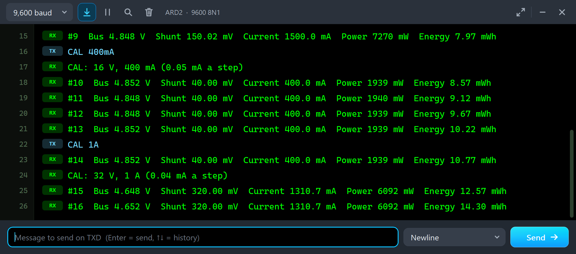
CAL 1A
CAL: 32 V, 1 A (0.04 mA a step)
#15  Bus 4.648 V  Shunt 320.00 mV  Current 1310.7 mA  Power 6092 mW  Energy 12.57 mWh
#16  Bus 4.652 V  Shunt 320.00 mV  Current 1310.7 mA  Power 6092 mW  Energy 14.30 mWh
Two limits hit at once. The shunt register stops at 320.00 mV, the widest PGA range, which is 3.2 A on the 0.1 ohm shunt. And the 1 A calibration (10240) turns that into 32000 x 10240 / 4096 = 80000 current steps, far more than the register's 32767, so it stops at 1310.7 mA and the chip sets OVF. The tool shows it:
RAW: the Registers by Hand
Back on CAL 2A and SERVO 250 mA, RAW reads the six registers with Wire:
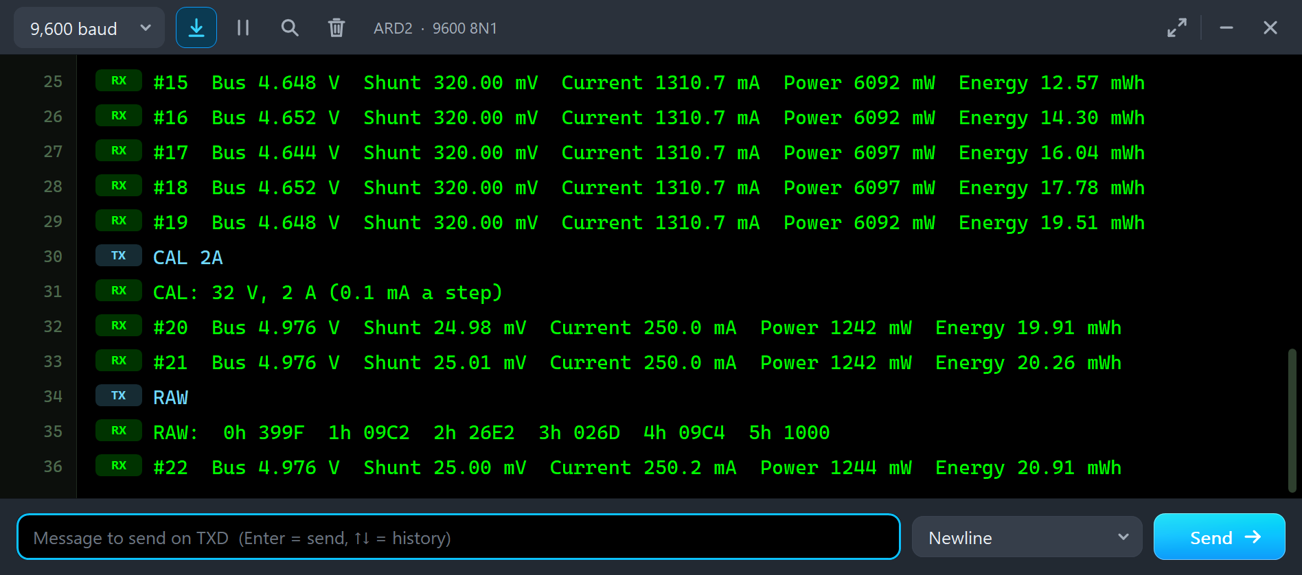
RAW
RAW:  0h 399F  1h 09C2  2h 26E2  3h 026D  4h 09C4  5h 1000
Each word decodes by the datasheet: 399F is the power-on configuration, 09C2 is 2498 x 10 uV = 24.98 mV, 26E2 shifted right by 3 is 1244 x 4 mV = 4.976 V with bit 1, CNVR, set, 026D is 621 x 2 mW = 1242 mW, 09C4 is 2500 x 0.1 mA = 250.0 mA, and 1000 is the calibration, 4096.
SLEEP and WAKE
SLEEP and WAKE are one call each: powerSave(true) writes the power-down mode into the Configuration register, powerSave(false) the continuous mode:
  else if (!strcasecmp(s, "SLEEP")) { ina219.powerSave(true); Serial.println(F("SLEEP: the INA219 powers down")); }
  else if (!strcasecmp(s, "WAKE")) { ina219.powerSave(false); Serial.println(F("WAKE: converting again")); }
While the INA219 slept, we clicked MOTOR 800 mA in the pop-up:
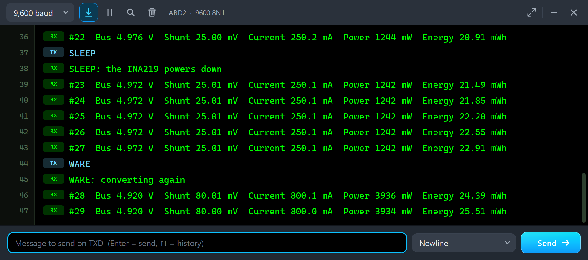
SLEEP
SLEEP: the INA219 powers down
#23  Bus 4.972 V  Shunt 25.01 mV  Current 250.1 mA  Power 1242 mW  Energy 21.49 mWh
#24  Bus 4.972 V  Shunt 25.01 mV  Current 250.1 mA  Power 1242 mW  Energy 21.85 mWh
WAKE
WAKE: converting again
#28  Bus 4.920 V  Shunt 80.01 mV  Current 800.1 mA  Power 3936 mW  Energy 24.39 mWh
In power-down the INA219 makes no conversions, but it still answers on I2C with its last values, so the readings froze at 250 mA. After WAKE, the next line read the motor's 800 mA. A frozen reading after a power-save is easy to miss on a real board.
The I2C and Readings Tools
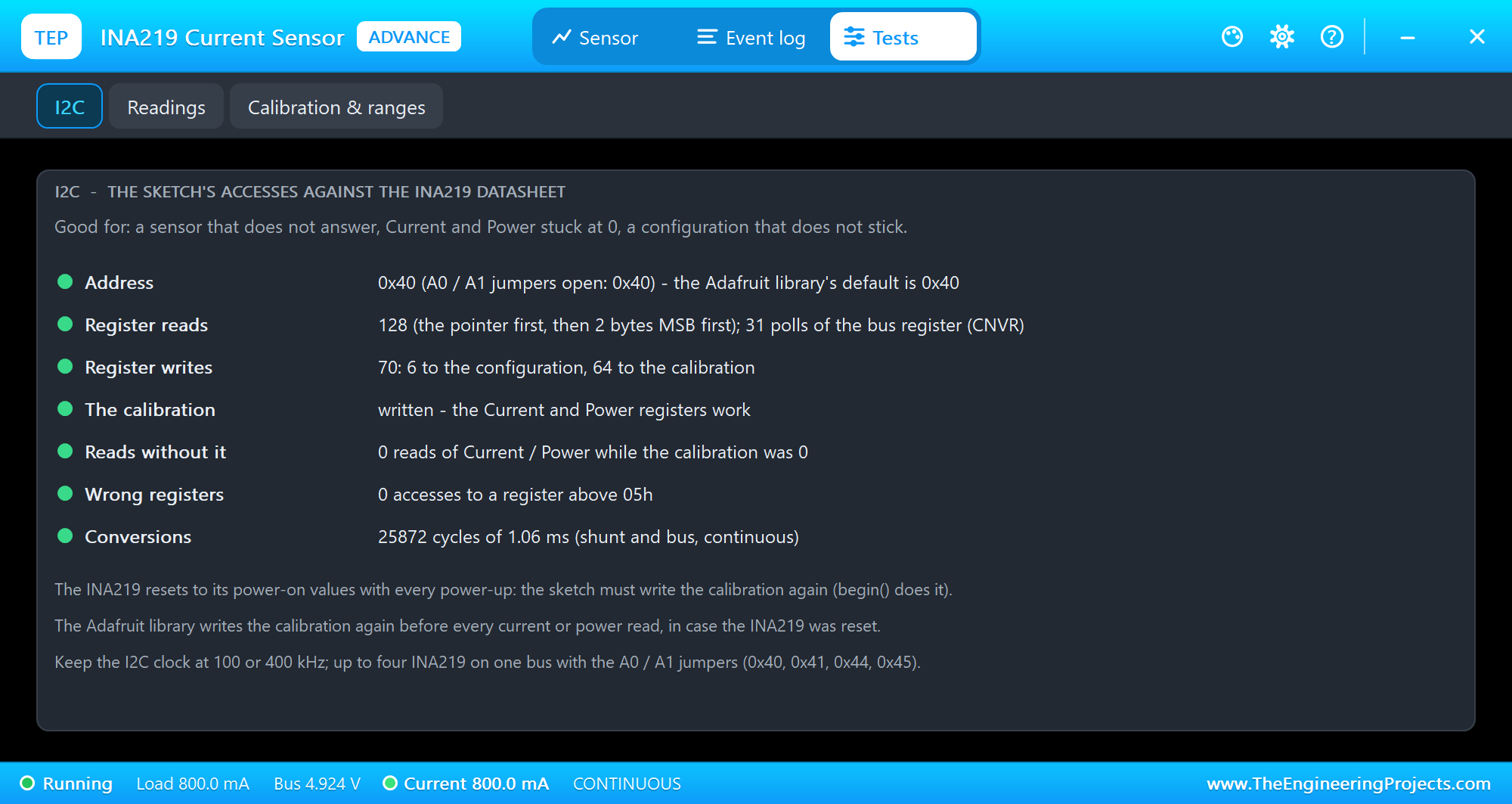
The I2C tool is the one to open for a sensor that does not answer, Current and Power stuck at 0, or a configuration that does not stick. It shows the address, the reads, the writes, whether the calibration was written, reads of Current or Power without it, wrong registers and the conversions. The Readings tool lists the last 12 transactions:
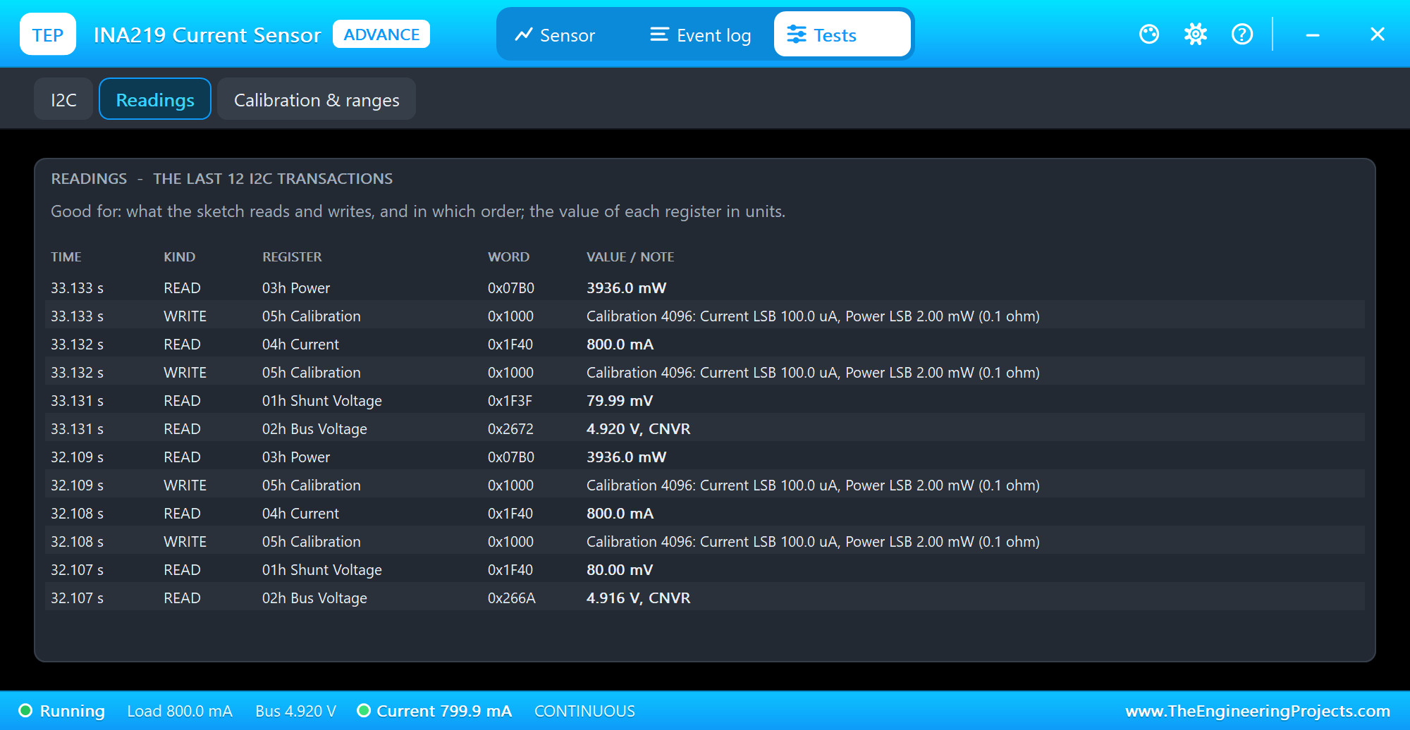
You can see the Adafruit library at work: before every current or power read it writes the calibration again, in case the INA219 was reset.
The Event Log
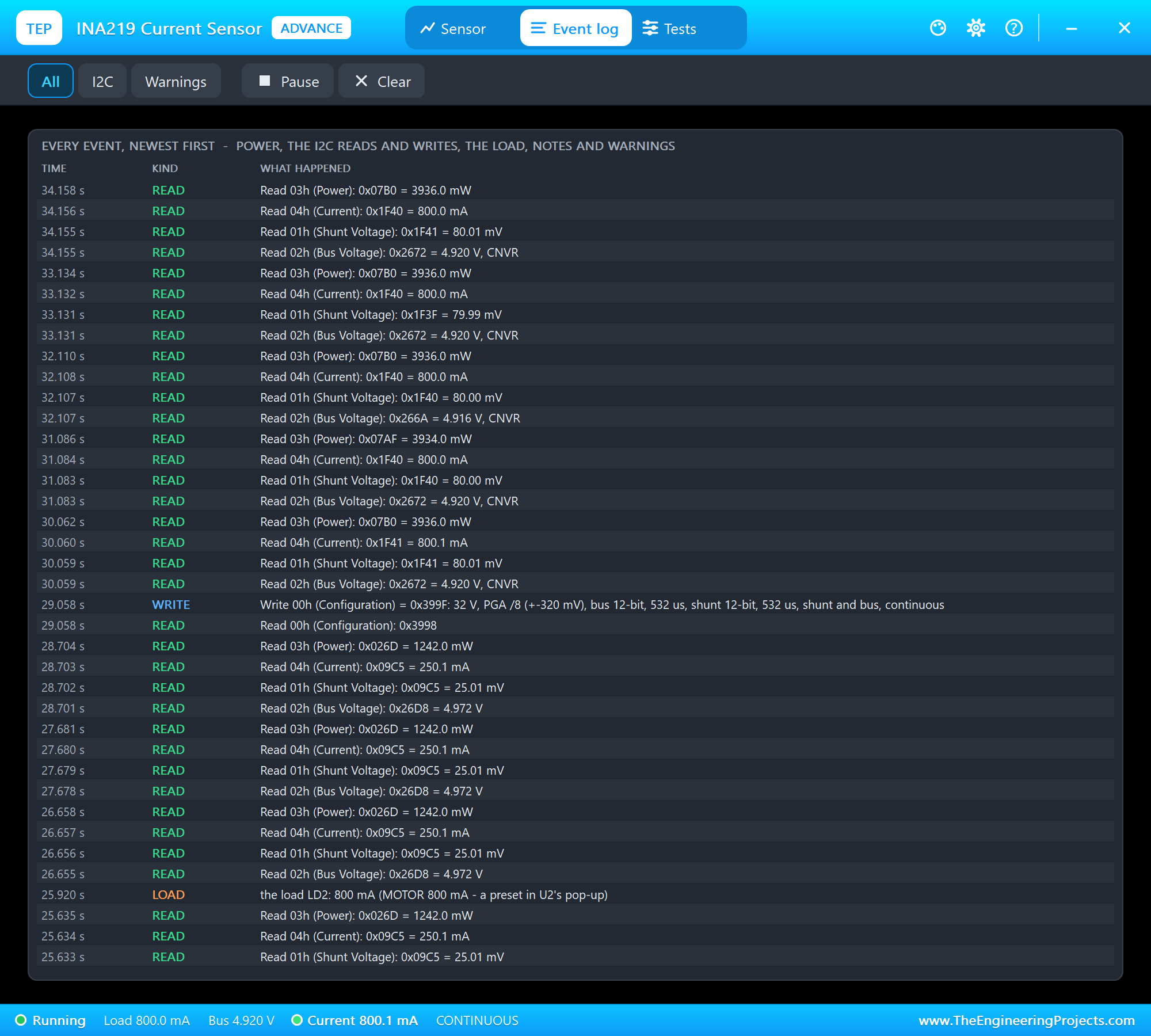
The Event log lists everything that happened, newest first: the power, every read and write with its register and value, the load's changes with where they came from, notes and warnings. Filter it by I2C or warnings, pause it, or clear it.
The Simulation Log
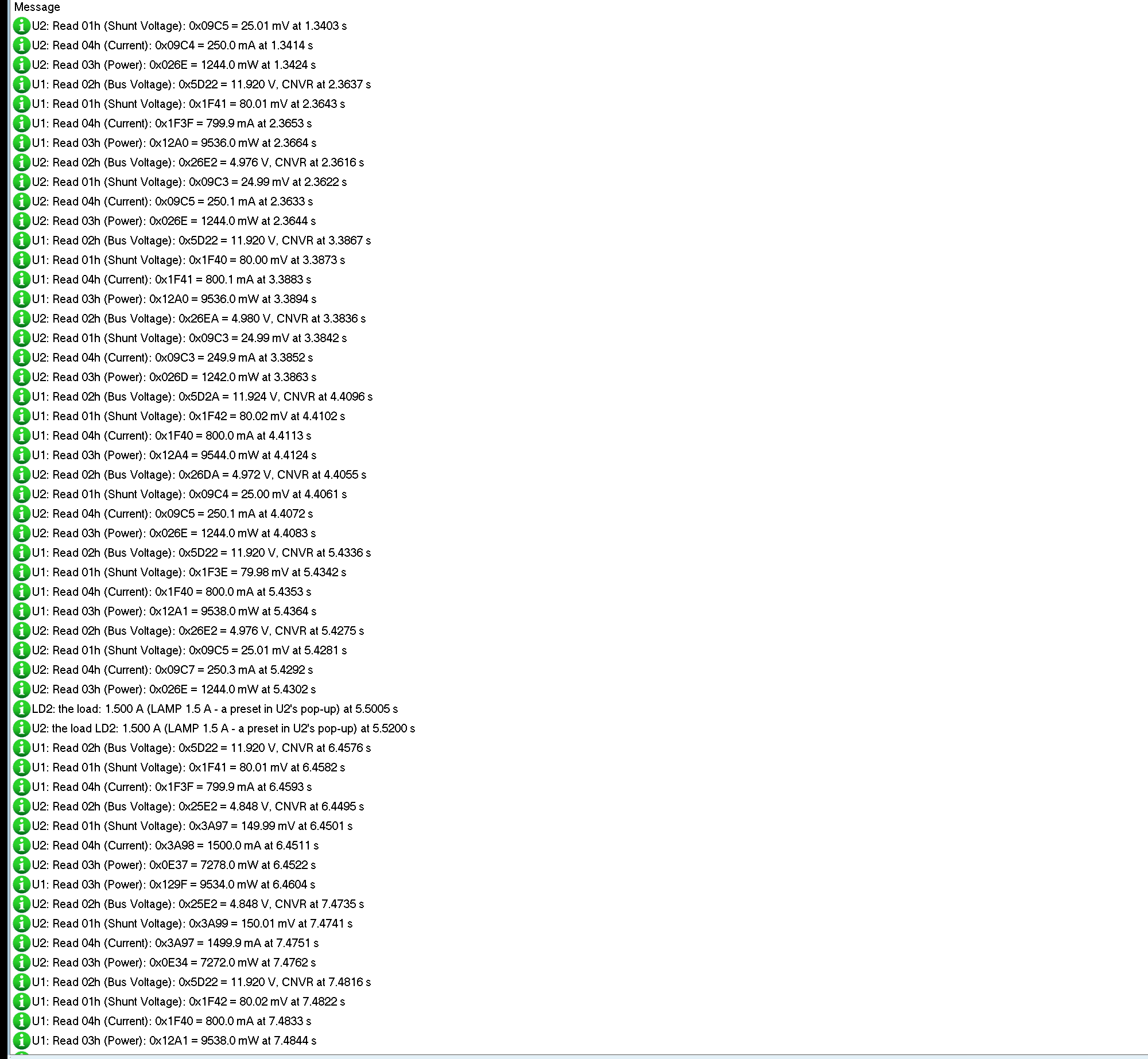
Every GY-219 and DC load also writes to the simulation log of Proteus, with the exact simulation time. This part shows one reading of node 1 and the LAMP preset on node 2:
U1: Read 02h (Bus Voltage): 0x5D2A = 11.924 V, CNVR at 4.4096 s
U1: Read 01h (Shunt Voltage): 0x1F42 = 80.02 mV at 4.4102 s
U1: Read 04h (Current): 0x1F40 = 800.0 mA at 4.4113 s
U1: Read 03h (Power): 0x12A4 = 9544.0 mW at 4.4124 s
LD2: the load: 1.500 A (LAMP 1.5 A - a preset in U2's pop-up) at 5.5005 s
U2: the load LD2: 1.500 A (LAMP 1.5 A - a preset in U2's pop-up) at 5.5200 s
Each reading is four register reads, about a millisecond apart: the bus with its CNVR flag, the shunt, the current and the power. The load logs its own change, and the INA219 logs which load changed and from where.
How the Model Works
The GY-219 is a mixed model. VCC, GND, VIN+ and VIN- are analog: the 0.1 ohm shunt is a real resistor between VIN+ and VIN- in the SPICE simulation of Proteus, VIN- sees the chip's 320 kohm bus input, and VCC its 1 mA. At the end of each conversion the INA219 reads VIN+ - VIN- and VIN- - GND from the solution and fills its registers, with the PGA and bus ranges, the resolution or averaging, the calibration maths and the noise. SCL and SDA are digital: Proteus runs every edge from the Arduino with its exact time, and the model pulls SDA low to acknowledge and to send. The DC load is analog too: a constant-current sink that draws the set current above 0.5 V.
Troubleshooting
- "INA219 not found": no power on VCC and GND, SDA and SCL swapped or missing, or another address; the PWR LED is off or the I2C LED never flashes.
- Current and Power 0: the calibration was never written;
begin()writes it. - The current stops at a round number: a range clips, the PGA or the Current register; see Calibration and ranges, and look at the OVER LED.
- A negative current: VIN+ and VIN- are swapped.
- The bus stops at 16 V: the 16 V range of CAL 400mA; use a 32 V calibration.
- The readings never change: the INA219 is powered down; WAKE.
- No part or no monitor: TEPINA219.DLL or TEPARDUINO.DLL is missing from MODELS and the project folder; a closed monitor opens again with a click on the UNO's USB port.
Things to Know Before Using a Real INA219
- Grounds: the INA219 measures on the high side, but the supply, the load and the Arduino must share GND.
- Limits: the GY-219's shunt reads up to 3.2 A, and VIN+ and VIN- take up to 26 V.
- Several modules: up to four on one bus with the A0 and A1 jumpers.
- Motors: a motor's current jumps when it starts; for the drivers that switch it, see our L9110S Motor Driver Library for Proteus.
Limitations of the Simulation
- Not modelled: the INA219's offset and gain errors (the datasheet: +-10 to +-100 uV offset, +-0.5 % gain), the SMBus timeout and alert, the shunt's temperature drift and self-heating; the load has no power limit.
- The LEDs, the badge, the panel button and the panels are TEP additions.
- The model is our own, written from the INA219 datasheet. This library is not made or endorsed by Texas Instruments, Adafruit, the makers of the GY-219 module or Labcenter.
- Licences: the demo sketch uses the Adafruit INA219 library 1.2.3 (BSD) and Adafruit BusIO 1.17.4 (MIT), which are not shipped; install them from the Library Manager. The demo's HEX file contains them and the Arduino AVR core 1.8.6 with LGPL-licensed code; the licence texts and the source links are in the README.
- Tested in Proteus 8.5 in October 2026 (the demo as shipped on two Arduino UNO V4.0 boards with their built-in monitors: both nodes reading, LAMP, CAL 400mA and the switch on node 1 with the mouse, the red X and PANEL, LAMP, CAL 400mA, CAL 1A with HEATER, RAW, SLEEP and WAKE on node 2, the three tools; 71.0 s of simulation took 136 s, about 0.5 x real time with the pop-up and both monitors open). Proteus 7 is not supported.
So, that was all about the INA219 Current Sensor Library for Proteus V1.0. I hope the shunt, the calibration and the ranges are clear now, so your power meter reads the right current from the first run. If you use the INA219 Current Sensor Library for Proteus in a project, please share it in the comments or in our forum, and if you have any questions, ask in the comments and I will help you out. Till the next tutorial, take care and have fun!