Hello friends, I hope you all are doing great. Today, I am going to share the new SIM800C GSM Library for Proteus V1.1. The SIM800C is SIMCom's quad-band GSM module, and many makers buy it on the small blue HW-537 board with a flexible antenna. This board has one habit that confuses many beginners: it stays switched off until its PWX power key is held LOW for more than a second. With this SIM800C Library for Proteus, you can learn that habit, send SMS, make calls and debug your GSM sketch on your PC, before you buy a SIM card or a 2 A power supply.
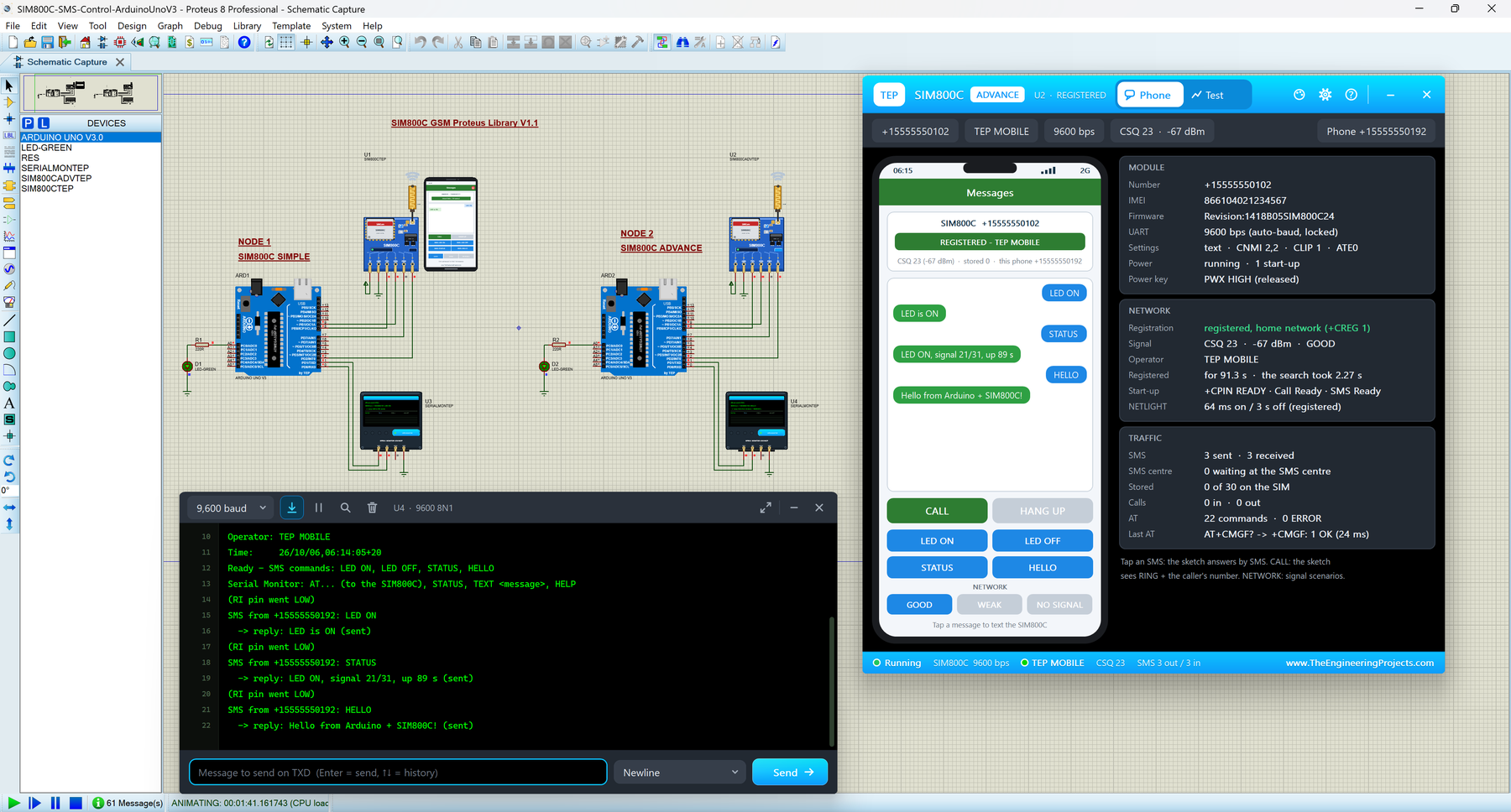
Version 1.1 gives you two devices: SIM800C Simple, with a virtual smartphone next to the module, and SIM800C Advance, with a pop-up window that holds the phone plus four measured GSM test tools. The Arduino SIM800C Proteus demo has two Arduino UNOs that switch their SIM800C on with PWX, control an LED by SMS, reject calls and talk to our TEP Serial Monitor, shown in its compact Simple interface.
NOTICE: This library is very special to our team. Our SIM800C model waits for its power key, learns your baud rate from the first "AT", reports +CPIN: READY, Call Ready and SMS Ready, and then texts and calls over a simulated network, just like the real board. It took our team a lot of hard work, many test runs and many design changes. Your feedback is the fuel that keeps us going, so please tell us what you think in the comments below or in the SIM800C Library board of our forum. And if our free libraries help you, you can buy us a coffee. So, let's get started with the SIM800C Library for Proteus:
What is the SIM800C GSM Module?
The SIM800C is a GSM / GPRS module made by SIMCom. It is quad-band (850, 900, 1800 and 1900 MHz) and needs 3.4 - 4.4 V. Your Arduino controls it over a UART (the two-wire TX / RX serial port) with AT commands: short text commands that start with "AT". For example, AT+CSQ asks for the signal strength and AT+CMGS sends an SMS.
For Arduino projects, the SIM800C usually comes on the HW-537 board: a blue PCB of about 31 x 27 mm with a micro-SIM socket underneath, an IPEX (u.FL) socket labelled GSM_ANT, two blue LEDs (PWR and NET), a 1000 µF capacitor and a level shifter made of two 2N7002 transistors. With it, an Arduino can send and receive SMS, make, answer and reject calls, read the signal, the operator and the network time, and run USSD codes such as *123#. GPRS data, Bluetooth and the (Chinese-only) text-to-speech of the board are not part of our simulation.
SIM800C or SIM800L: What is the Difference?
Both modules belong to SIMCom's SIM800 family and answer almost the same AT commands; even ATI gives the same text, "SIM800 R14.18". The difference you notice on your desk is the board:
| SIM800C (blue HW-537 board) | SIM800L (red mini board) | |
|---|---|---|
| Power input | 5V pin (two diodes drop it for the module) | VCC, about 3.7 - 4.2 V |
| Switching on | Stays OFF until PWX is held LOW for more than 1 s | Starts as soon as VCC is applied |
| UART level | TXD / RXD shifted to V_TTL (3.3 or 5 V) | 2.8 V logic (a divider on RXD) |
| Antenna | IPEX socket (GSM_ANT) and a flexible antenna | Spring antenna |
| Chip | 42 pads, no FM radio | 88 pads, with an FM radio |
| Our library | This article | SIM800L Library for Proteus |
Have the red board? Then the SIM800L Library for Proteus is your download. The two libraries use separate models, so a TEP SIM800L cannot text a TEP SIM800C.
GSM Terms You Will See in This Article
| Term | Meaning |
|---|---|
| AT command | A text command to the module, ending with a carriage return; it answers OK or ERROR |
| URC | "Unsolicited result code": a line the module sends on its own, such as RING, +CLIP or SMS Ready |
| PWX (PWRKEY) | The power key of the HW-537: held LOW for more than 1 s, it switches the module on or off |
| V_TTL | The board pin that sets the logic level of TXD / RXD (5 V for an Arduino UNO) |
| Auto-bauding | The SIM800C learns your UART speed from the first "AT" it receives |
| SMS Ready | The last start-up message; after it, the module takes SMS commands |
| CSQ | Signal quality from 0 to 31 (99 = no signal); 20 and more is good |
| RI | Ring Indicator pin: LOW while a call rings, a short LOW pulse for each new SMS |
| +CLIP | The caller ID line that follows each RING |
What's New in SIM800C Library for Proteus V1.1
- A library of its own: v1.0 shipped the SIM800C and the SIM900A together; now each has its own download and article, sharing one model file,
TEPSIMCOM.DLL. - Two devices in
TEPSIM800C.LIB: SIM800C Simple (SIM800CTEP, the v1.0 device) and SIM800C Advance (SIM800CADVTEP), with its own default numbers. - Board: a ring LED round the antenna lead and a lamp in its tip (orange = sending, green = receiving), a PANEL / OPEN PANEL button and a SIMPLE / ADVANCE badge. PWR and NET stay blue, like on the real HW-537.
- Four GSM test tools in the Advance pop-up: Network, SMS round trip, Call and AT check.
- A more realistic network: the search takes 2.2 - 3.2 s (weak signal 2.8 - 3.4 s) instead of a fixed 3 s, and every SMS takes its own time: 1.2 - 1.9 s to the module and 1.7 - 2.5 s back (v1.0: always 1.5 s and 2 s).
- Model fixes: AT+CFUN=1,1 sends its whole OK before it restarts, AT+CFUN=1 after AT+CFUN=0 reports +CREG: 2, and the phone shows 60 characters per message (v1.0: 32).
- TEP Serial Monitor in the demo instead of the Virtual Terminal, and a smarter sketch that takes AT commands from the monitor and sets the module up again after a restart or a power-down.
- Lighter package: about 1.5 MB, without the C++ source code.
SIM800C Library for Proteus: Simple vs Advance
Both devices run the same SIM800C model with the same properties; only the panel differs:
| Feature | Simple | Advance |
|---|---|---|
| Full SIM800C model (PWX power key, AT commands, SMS, calls, RI pin) | ✔ | ✔ |
| Blue PWR and NET LEDs, antenna ring and tip lamp, animated waves | ✔ | ✔ |
| Virtual phone drawn on the schematic | ✔ | ✘ |
| Phone in a pop-up window you can move, resize and minimise | ✘ | ✔ |
| MODULE, NETWORK and TRAFFIC cards, with the power key state | ✘ | ✔ |
| Network test (restart with the power key, radio off / on) | ✘ | ✔ |
| SMS round trip and call tests | ✘ | ✔ |
| AT check with response times | ✘ | ✔ |
| TEP Dark / Light theme, text size, Help page with Copy diagnostics | ✘ | ✔ |
| Same device name as v1.0 (old designs keep working) | ✔ | ✘ |
Choose Simple to keep the phone next to your circuit, and Advance when your sheet is full or you want hard numbers about your GSM code. The demo has one of each.
Download SIM800C Library for Proteus
Click the button below to download SIM800C-GSM-Library-for-Proteus-v1.1.zip (about 1.5 MB):
SIM800C GSM Library for Proteus V1.1- README.txt: a detailed guide to the files, the wiring and the model.
- Proteus Library Files:
TEPSIM800C.LIB(both devices),TEPSERIALMON.LIBand our Arduino UNO libraryArduinoV3TEP.LIB/ArduinoV3TEP.IDX. - Proteus Model Files:
TEPSIMCOM.DLLandTEPSERIALMON.DLL. - Proteus Simulation:
SIM800C-SMS-Control-ArduinoUnoV3.pdsprj, the .hex file and copies of both DLLs. - Arduino Code:
SIM800C_SMS_Control.inoand AltSoftSerial 1.4 (MIT licence).
One model, two libraries: TEPSIMCOM.DLL is shared with our SIM900A Library for Proteus. Both packages ship the identical file, so you can install either or both, and a SIM800C and a SIM900A in one design can text and call each other. Your v1.0 designs keep working too.
If you don't have Proteus yet, read How to Download and Install Proteus 7 and 8. New to libraries? Follow How to Install a New Library in Proteus.
How to Install SIM800C Library for Proteus
- Close Proteus and extract the whole zip file.
- Copy the four files from Proteus Library Files into the LIBRARY folder, usually
C:\Program Files (x86)\Labcenter Electronics\Proteus 8 Professional\LIBRARY(on some PCsC:\ProgramData\Labcenter Electronics\Proteus 8 Professional\LIBRARY). - Copy
TEPSIMCOM.DLLandTEPSERIALMON.DLLinto the MODELS folder. - Start Proteus, press P and search for SIM800C. You get the Simple and the Advance device (category Peripherals > Wireless).
Updating from v1.0? Replace TEPSIM800C.LIB and TEPSIMCOM.DLL, and delete any TEPSIM800C.IDX from LIBRARY. A v1.0 design keeps its old symbol and runs with the new model; re-pick the part to get the v1.1 board and the red X. Tested in Proteus 8.5; Proteus 7 is not supported.
The HW-537 SIM800C Board in Proteus
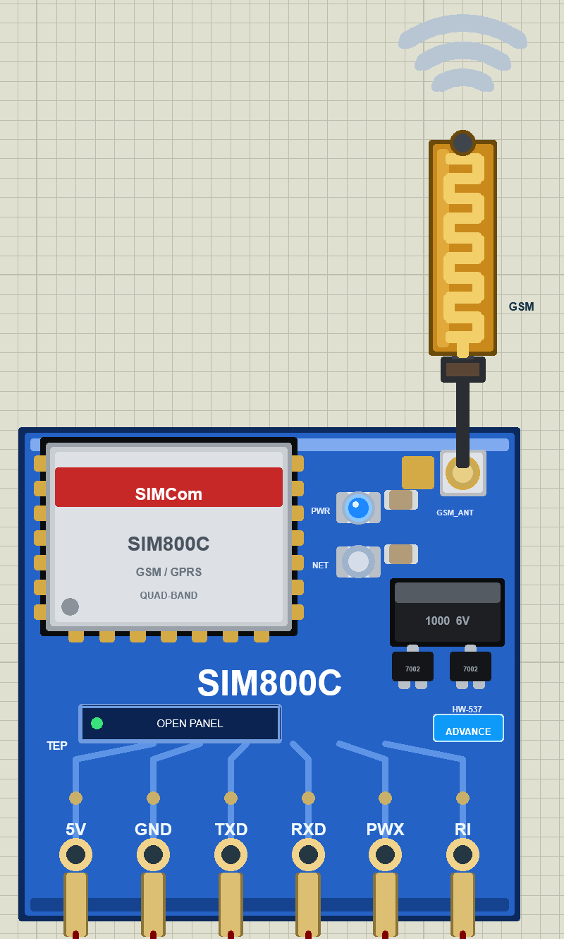
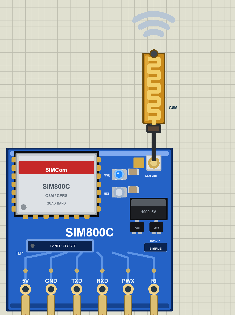
We designed the module as a clean TEP board in the blue of the HW-537: the silver SIM800C can with its red SIMCom band, the IPEX socket labelled GSM_ANT with a black cable up to the gold flexible antenna, the PWR and NET LEDs, the "1000 6V" capacitor and the two "7002" level-shifter transistors. Here is the SIM800C Advance:
Pinout
The real HW-537 has two 8-pin rows that also carry V_TTL, VBAT, DTR, VRTC and the audio pins. Our part keeps the six pins an Arduino needs:
| Pin | Function | Demo connection |
|---|---|---|
| 5V | Power input of the board | Supply |
| GND | Ground | GND |
| TXD | Serial output: answers and URCs | Arduino D8 |
| RXD | Serial input: AT commands from the Arduino | Arduino D9 |
| PWX | Power key: LOW for more than 1 s = on / off (pulled up by the module) | Arduino D7 |
| RI | Ring Indicator: LOW while a call rings, a 120 ms LOW pulse for each new SMS | Arduino D2 (INT0) |
There is no V_TTL pin: the model assumes it is tied to your Arduino's supply, as it must be on the real board.
LEDs, Antenna and Waves
| Indicator | What it shows |
|---|---|
| PWR LED (blue) | On whenever the board has 5 V, even while the module is switched off |
| NET LED (blue) | Off while the module is off, 64 ms on / 800 ms off while searching, 64 ms on / 3 s off when registered |
| Ring LED round the antenna lead, tip lamp | Orange while the module sends (SMS, call set-up), green while it receives, both in turn during a call |
| Waves above the antenna | Ripple out while sending, in while receiving |
The board button is PANEL on the Simple (green dot = SHOWN, grey dot = CLOSED) and OPEN PANEL on the Advance.
Component Properties
| Property | Meaning | Default |
|---|---|---|
| SIMNUM | The module's SIM number | +15555550101 (Advance +15555550102) |
| PHONENUM | Number of its virtual phone | +15555550191 (Advance +15555550192) |
| OPERATOR | Network operator name | TEP MOBILE |
| SIGNAL | Signal at start: GOOD, WEAK or NONE | GOOD |
| CLOCK | Network time: PC (your PC's time and time zone) or a fixed YYYY-MM-DD HH:MM:SS | PC |
| REVISION | The firmware build that AT+CGMR reports | 1418B05SIM800C24 |
Every TEP SIM800C, TEP SIM900A and virtual phone in a design share one simulated network, so give each module its own numbers.
Switching the SIM800C On: The PWX Power Key
This is the first lesson of every SIM800C, so let's look at it before the phone. Start the SIM800C Proteus simulation and look at the boards: the blue PWR LED is lit because the board has 5 V, but the NET LED stays dark, because the SIM800C itself is still off. Both Serial Monitors print "Switching the SIM800C on (PWX LOW for 1.2 s)...": the sketch is pressing the power key.
PWX is the module's PWRKEY pin, pulled up inside. The model follows the SIM800C data sheet:
- held LOW for more than 1 s, it switches the module on;
- the same pulse while it runs switches it off (NORMAL POWER DOWN, off 2 s after the press began);
- held LOW for 33 s, it restarts the module;
- tied to GND, it switches the module on at power-up (the usual auto-boot trick) and again after
AT+CPOWD=1.
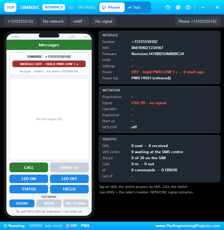
Until somebody presses the key, the phone says MODULE OFF - HOLD PWX LOW 1 s, and the Advance pop-up adds a tip under its phone:
Here is the code that presses the key. It never drives PWX HIGH: it pulls the pin LOW as an OUTPUT, waits 1.2 s and turns it back into an INPUT, so the module's pull-up takes over:
    Serial.println(F("Switching the SIM800C on (PWX LOW for 1.2 s)..."));
    pinMode(PWX_PIN, OUTPUT);
    digitalWrite(PWX_PIN, LOW);
    delay(1200);
    pinMode(PWX_PIN, INPUT);           // released
    // Auto-baud: the SIM800C learns the speed from the first "AT" (about 3 s after the PWX pulse).
    if (!answers(20, 500)) return false;
Because the same pulse would switch a running module off, the sketch first sends "AT". If the module answers, for example after you reset the UNO, it prints "SIM800C is already on" and leaves PWX alone:
  bool switchedOn = false;
  if (answers(again ? 10 : 3, again ? 500 : 300)) {
    if (!again) Serial.println(F("SIM800C is already on"));    // e.g. after a reset of the UNO
  } else {
From Power-On to SMS Ready
- Right after switching on, the module sends SIMCom's sync bytes
00 49 49 49 49 FF FF FF FFat 115200 bps. At 9600 bps they can look like a few garbage characters, which is normal. - It is auto-bauding (factory setting AT+IPR=0): it says nothing until it receives "AT" at any speed from 1200 to 115200 bps, then answers at that speed.
- A host that has sent "AT" sees +CPIN: READY (3 s after switching on), Call Ready (4.5 s) and SMS Ready (5.5 s).
- 2.2 - 3.2 s later, the module registers to the network.
The Advance pop-up shows this phase clearly: U2 · STARTING, "No network", "UART -", "No signal" and the power key "PWX HIGH (released)". The UART row stays empty because the module has not learnt the baud rate yet; the status bar says "SIM800C auto-baud":
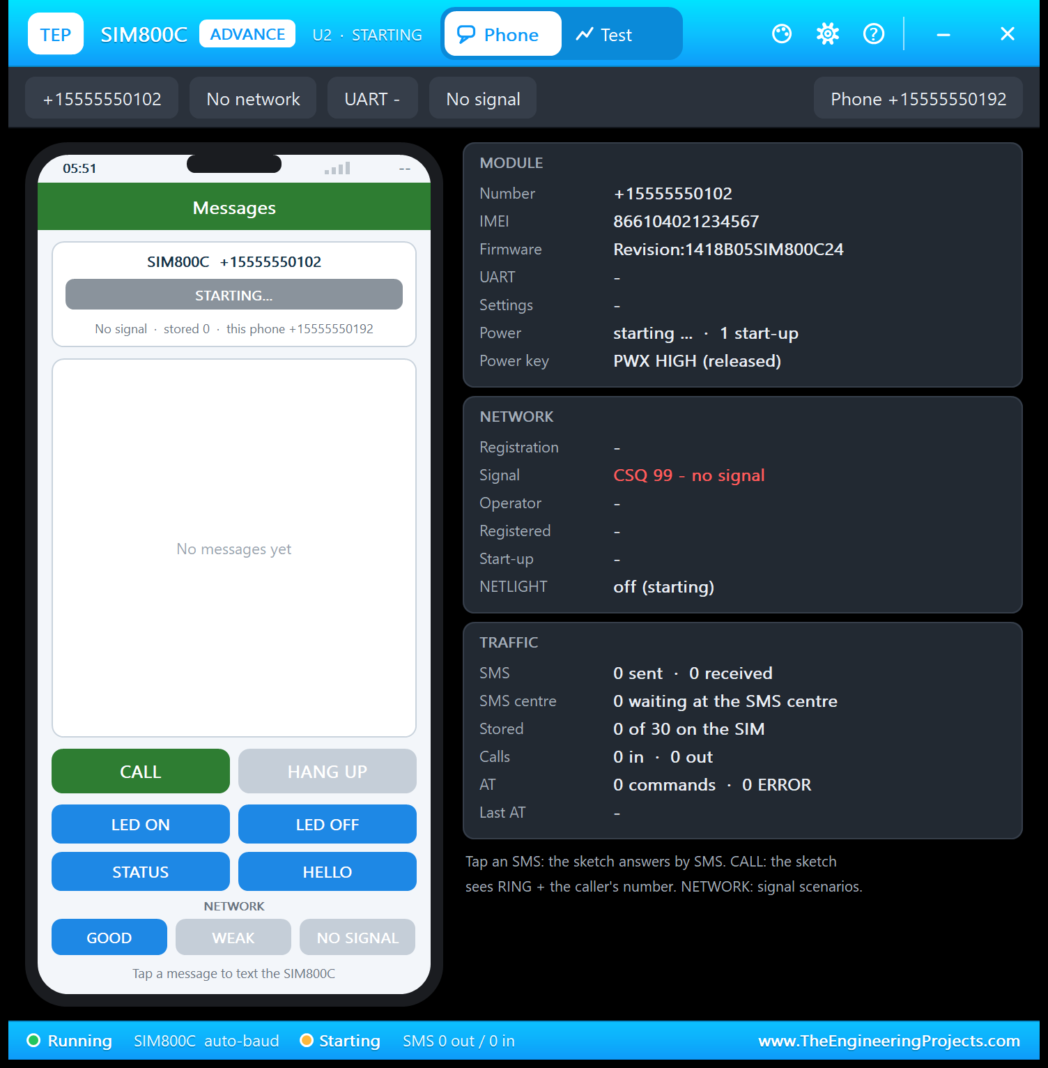
In the demo, both modules are on, set up and registered about 12 s after Run (simulation time).
The Virtual Phone: SIM800C Simple
Beside the Simple module, we have drawn a smartphone with a Messages app and its own number. It texts the SIM800C, calls it, answers its calls and shows every SMS it receives as a chat bubble.
| Part | What it does |
|---|---|
| Status bar | The network time and "TEP 2G" |
| Module card | The module's number, its state (NO POWER - CHECK 5V / GND, MODULE OFF - HOLD PWX LOW 1 s, PWX LOW - SWITCHING..., STARTING..., NORMAL POWER DOWN, SEARCHING FOR NETWORK, NO SIGNAL, RADIO OFF or REGISTERED - operator), CSQ, stored SMS and the phone's own number |
| Conversation | Blue bubbles (right) = sent by the phone, green bubbles (left) = received from the module, plus call events |
| CALL / ANSWER | Calls the SIM800C, or answers a call from it |
| HANG UP | Ends or rejects the call (the module gets NO CARRIER) |
| SMS: LED ON, LED OFF, STATUS, HELLO | Text the SIM800C (delivered after 1.2 - 1.9 s) |
| NETWORK | GOOD, WEAK or NO SIGNAL |
| Tip line, red X | A reminder of PWX or AT+CMGF=1 when needed; the X closes the phone |
Talking to the Arduino by SMS
Tap SMS: STATUS. The SMS reaches the module, its RI pin drops LOW for 120 ms, and the sketch answers with the LED state, the signal and its up time. Here is U1's phone after LED ON, two STATUS messages and HELLO:
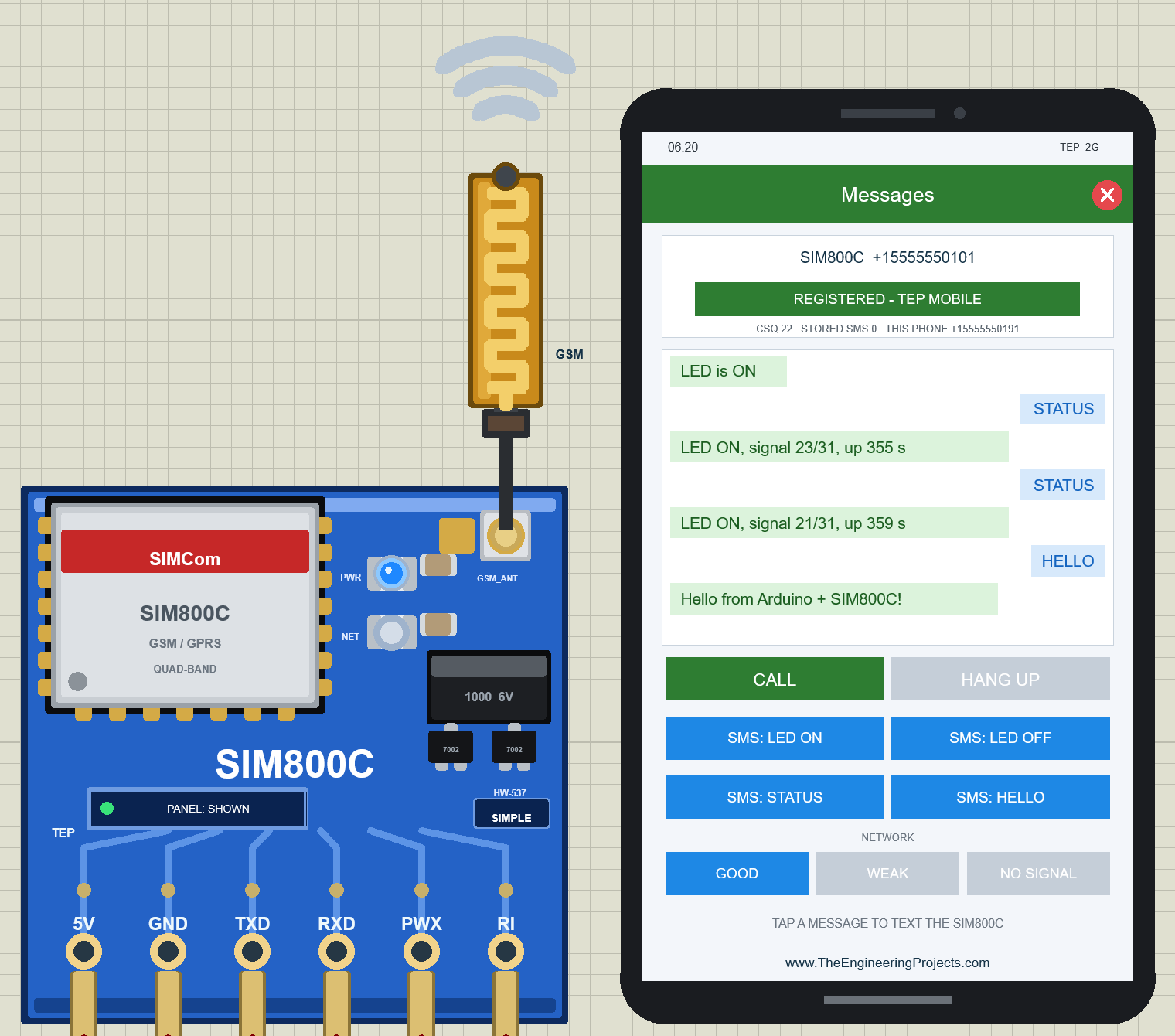
The two STATUS replies say "signal 23/31, up 355 s" and "signal 21/31, up 359 s": with GOOD, the signal moves between CSQ 21 and 23, like the bars of a real phone. While the module sends a reply, the antenna's ring LED and tip lamp light orange and the waves ripple out; an incoming SMS lights them green.
Calling the Module
Tap CALL. After 2 s, the module sends RING and the caller ID, the RI pin goes LOW, and the sketch prints the number and rejects the call with ATH. The phone shows "call rejected (busy)":
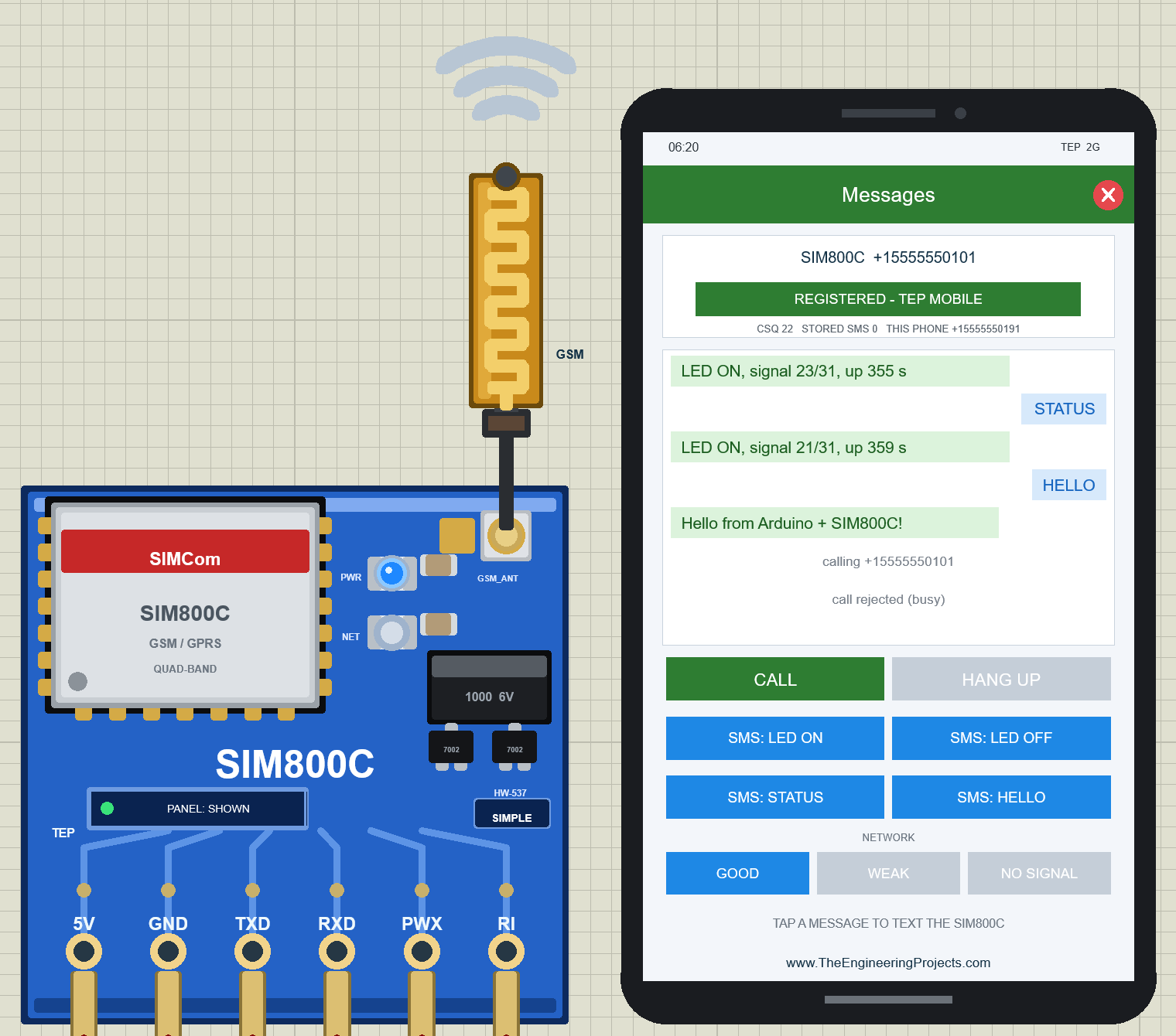
The SIM800C's caller ID line looks like this: +CLIP: "+15555550191",145,"",0,"",0. The SIM900A leaves the first 0 empty, which breaks parsers that expect a number there; our sketch only copies the text between the first pair of quotes, so the rest of the line does not matter to it.
Closing the Phone
Need room on the sheet? Click the red X in the phone's Messages bar. The board button then says PANEL: CLOSED with a grey dot, while the module and the sketch keep running. Click PANEL to bring the phone back.
SIM800C Advance: The Pop-Up Panel
The Advance device keeps only the board on the schematic. At Run, a TEP pop-up window opens with the look of our TEP Serial Monitor and no Windows title bar: move it by its header, resize or minimise it, and reopen it with OPEN PANEL after you close it. The header holds the part's state, the Phone and Test tabs and the theme, Settings and Help icons; the chips below show the numbers, the operator, the UART speed and the signal.
The Phone Page
The Phone page holds the same phone beside three cards. Here it is after the phone texted LED ON, STATUS and HELLO:
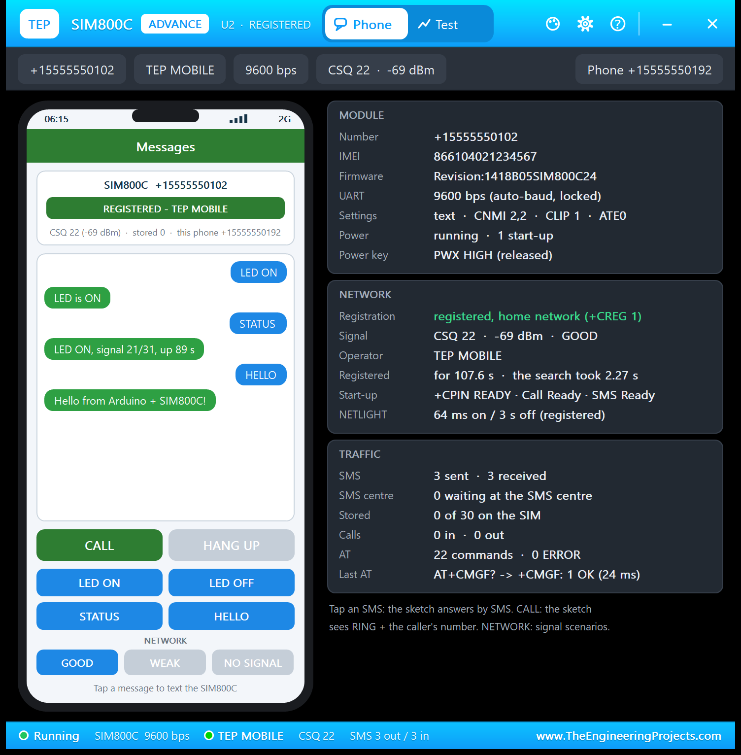
- MODULE: number, IMEI, firmware Revision:1418B05SIM800C24, UART "9600 bps (auto-baud, locked)", the settings the sketch made ("text · CNMI 2,2 · CLIP 1 · ATE0"), power "running · 1 start-up" and the power key "PWX HIGH (released)", which tells you at a glance whether your sketch still holds the key down.
- NETWORK: registered, home network (+CREG 1); CSQ 22 · -69 dBm · GOOD; TEP MOBILE; registered for 107.6 s after a search of 2.27 s; the start-up messages (+CPIN READY · Call Ready · SMS Ready); NETLIGHT 64 ms on / 3 s off.
- TRAFFIC: 3 SMS sent and 3 received, 0 waiting at the SMS centre, 22 AT commands with 0 ERROR, and the last exchange "AT+CMGF? -> +CMGF: 1 OK (24 ms)", the sketch's 30-second health check.
No Signal and the SMS Centre
Click NO SIGNAL. The phone's chip turns red, the header says U2 · NO SIGNAL, the NETWORK card shows "searching (+CREG 2)" and "CSQ 99 - no signal", and NETLIGHT goes back to 64 ms on / 800 ms off. (I took this shot after the tests below, hence 6 start-ups and three rejected calls.)
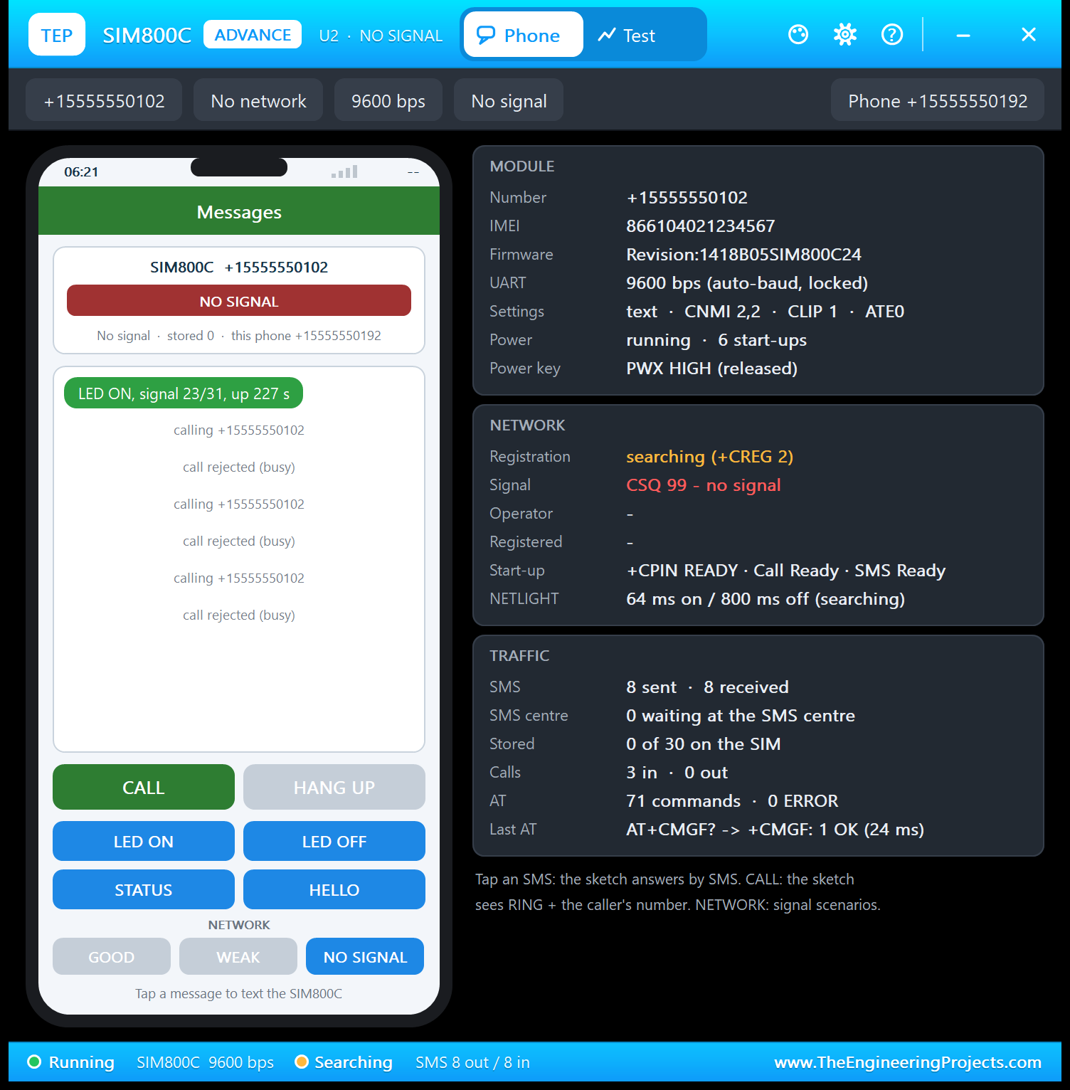
Without network, calls drop and AT+CMGS answers ERROR after 2 s. An SMS sent to the module meanwhile waits at the simulated SMS centre and is delivered when the module registers again; click GOOD to see it arrive. WEAK keeps the module registered with CSQ 7 - 9, but every SMS takes 2.5 times as long: a good check for your sketch's time-outs.
The Test Page: GSM Test Tools
The Test tab has four tools, and every number on it is measured on the running model, the same way your Arduino sees the module. A tool refuses to start, with the reason, when the module is off, another test runs or a call is in progress.
1. Network: How Long After PWX Can You Text?
Choose Restart or Radio off / on and 3, 5 or 10 runs. Restart really switches the module off and on again with its power key (PWRKEY LOW for 1 s, as the HW-537's PWX pin does) and times every step from the key press. Five runs:
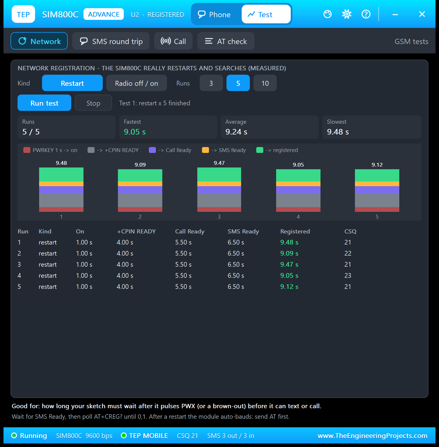
Every run shows the same first steps: on after 1.00 s, +CPIN READY after 4.00 s, Call Ready after 5.50 s and SMS Ready after 6.50 s. Only the network search changes: registered after 9.48, 9.09, 9.47, 9.05 and 9.12 s. So, after pulsing PWX, your sketch should expect to wait more than 9 s before it can text or call: wait for SMS Ready, then poll AT+CREG? until it answers 0,1.
A restarted module has also forgotten its settings and auto-bauds again. The demo sketch's 30-second check noticed this and set the module up again after each run; watch U4 while the test runs.
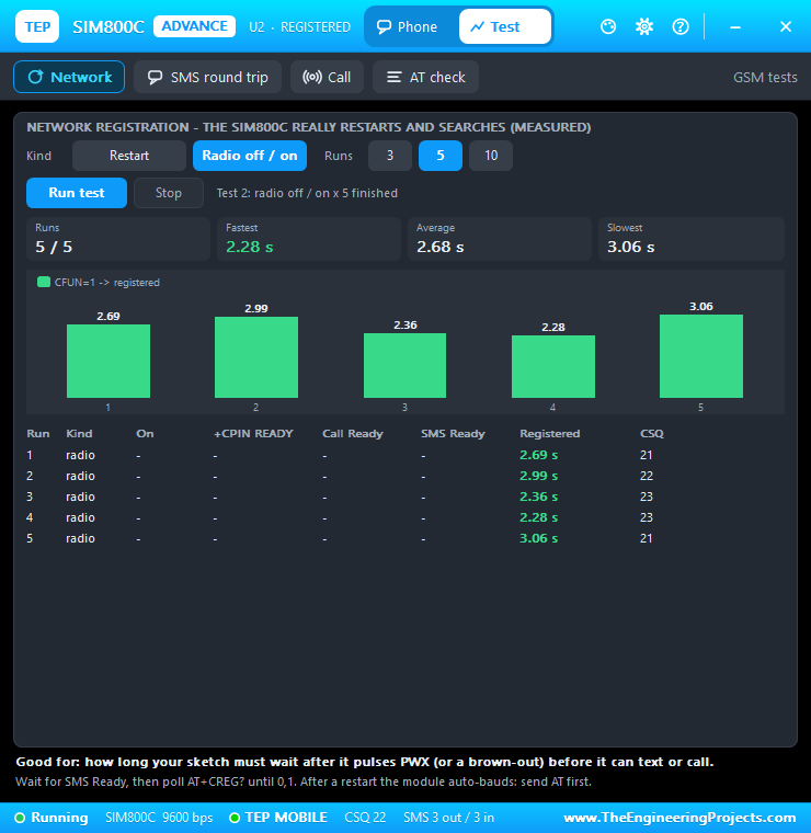
Radio off / on switches only the radio off for 1 s and on again (like AT+CFUN=0 / 1). The UART and the settings stay, and the search takes 2.28 to 3.06 s in this PC render:
2. SMS Round Trip
This tool tests your sketch. The phone texts LED ON, LED OFF, STATUS or HELLO 3, 5 or 10 times, and each reply SMS stops the clock. STATUS, 5 runs:
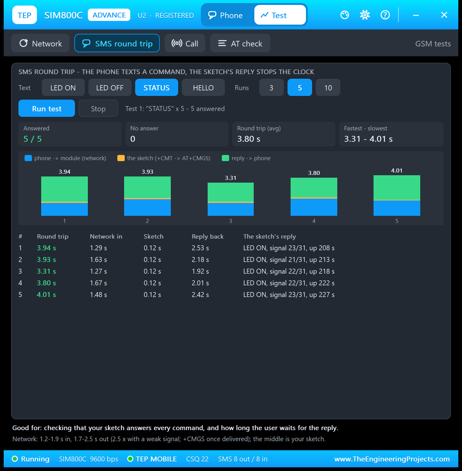
All five were answered in 3.31 to 4.01 s (average 3.80 s). The network in took 1.27 to 1.67 s, the sketch 0.12 s (from +CMT to its AT+CMGS) and the reply back 1.92 to 2.53 s. The network legs now differ for every SMS, like on a real network; the reply leg also includes the text's time on the 9600 bps UART. Good for: catching a sketch that misses commands or answers slowly (no reply within 30 s counts as "no answer").
3. Call Test
The phone calls the module 1, 3 or 5 times. The tool records the first RING, the module's own +CLIP line, the RI pin and whether your sketch answered (ATA) or rejected (ATH) the call:
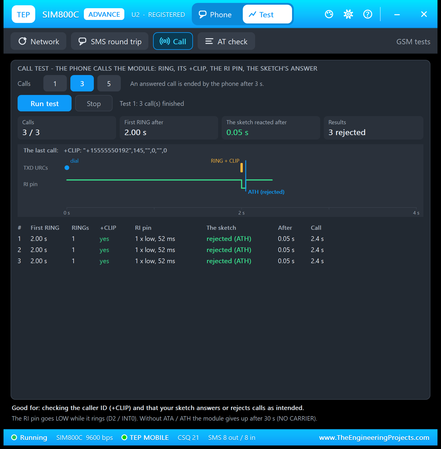
All three calls rang 2.00 s after dialling, RI went LOW once for 52 ms, and the sketch rejected each call 0.05 s after the first RING. Above the timeline is the module's caller ID line, +CLIP: "+15555550192",145,"",0,"",0. An answered call is ended by the phone after 3 s; without ATA or ATH, the module gives up after 30 s (NO CARRIER). Good for: checking the caller ID, the RI interrupt on D2 (INT0) and your call handling.
4. AT Check
The AT check shows what twelve read-only queries answer right now and the last 8 AT commands your Arduino sent, with the reply and the response time:
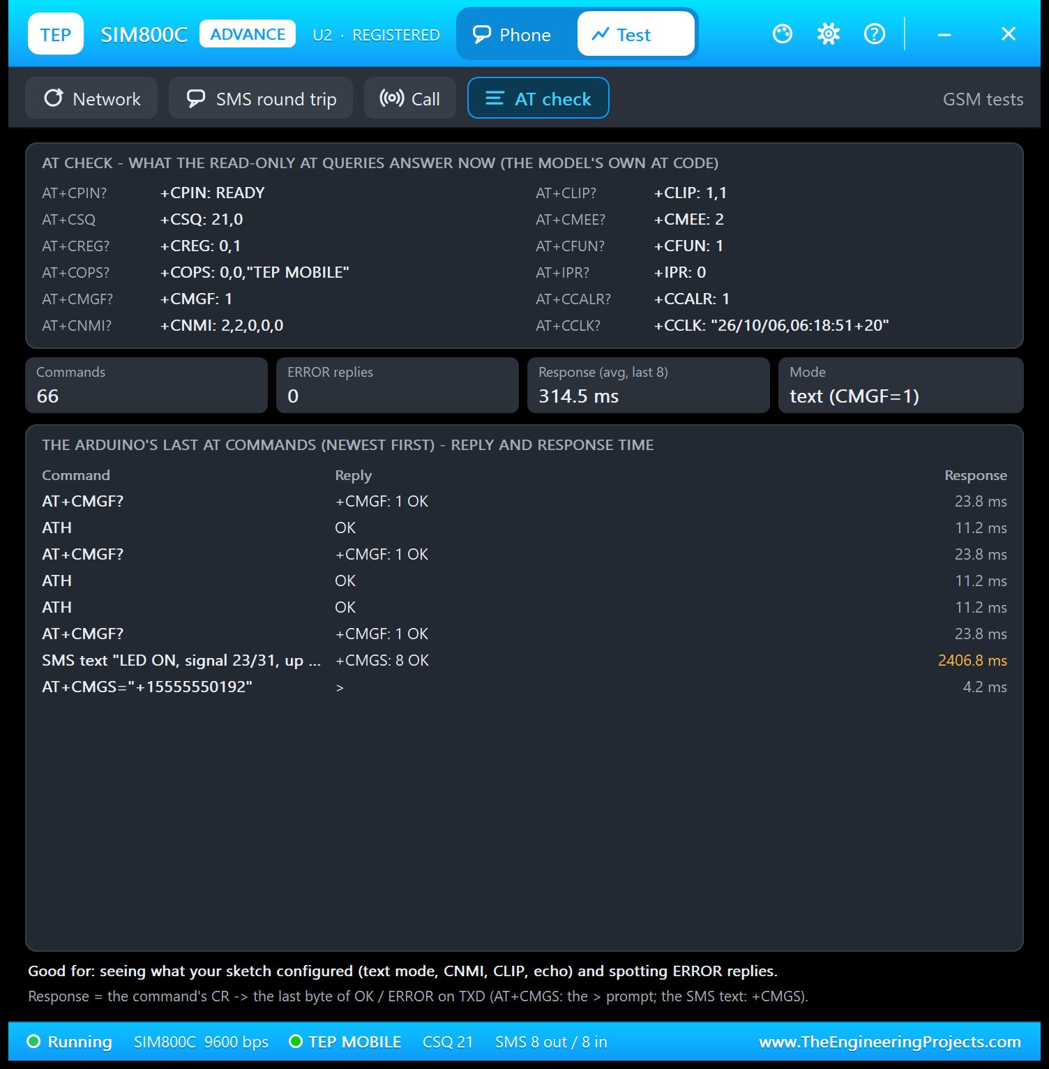
The module was ready (+CCALR: 1), registered (+CREG: 0,1), in text mode with +CNMI: 2,2,0,0,0 and +CLIP: 1,1, and +IPR: 0 means auto-bauding. Now compare the times: AT+CMGF? took 23.8 ms and ATH 11.2 ms, but the SMS text took 2406.8 ms until "+CMGS: 8 OK". The SIM800C answers +CMGS only after the SMS has been delivered, so this time includes the network, almost exactly the 2.42 s reply leg of the last round trip. (The SIM900A answers before delivery, as you will see in our SIM900A Library for Proteus.) A sketch that waits only a second for +CMGS would think every SMS failed; the demo waits up to 30 s:
return waitFor("+CMGS:", 30000) && waitFor("OK", 2000);Settings and Help
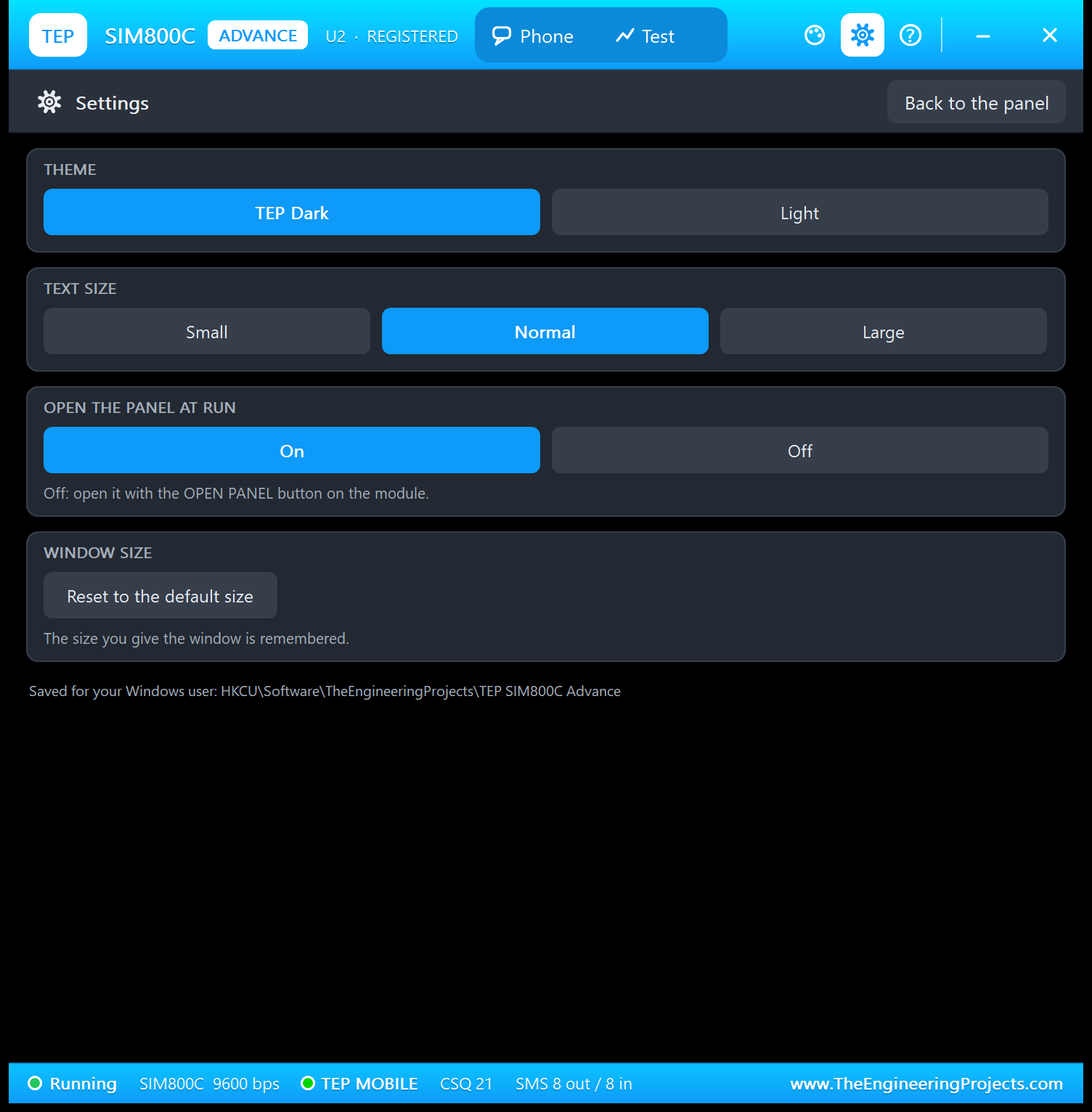
These pages work like in our SIM800L Library for Proteus and ESP-01 Library for Proteus. The gear opens Settings: theme (TEP Dark or Light), text size, open the panel at Run, and a reset for the window size, which is remembered. Everything is saved for your Windows user.
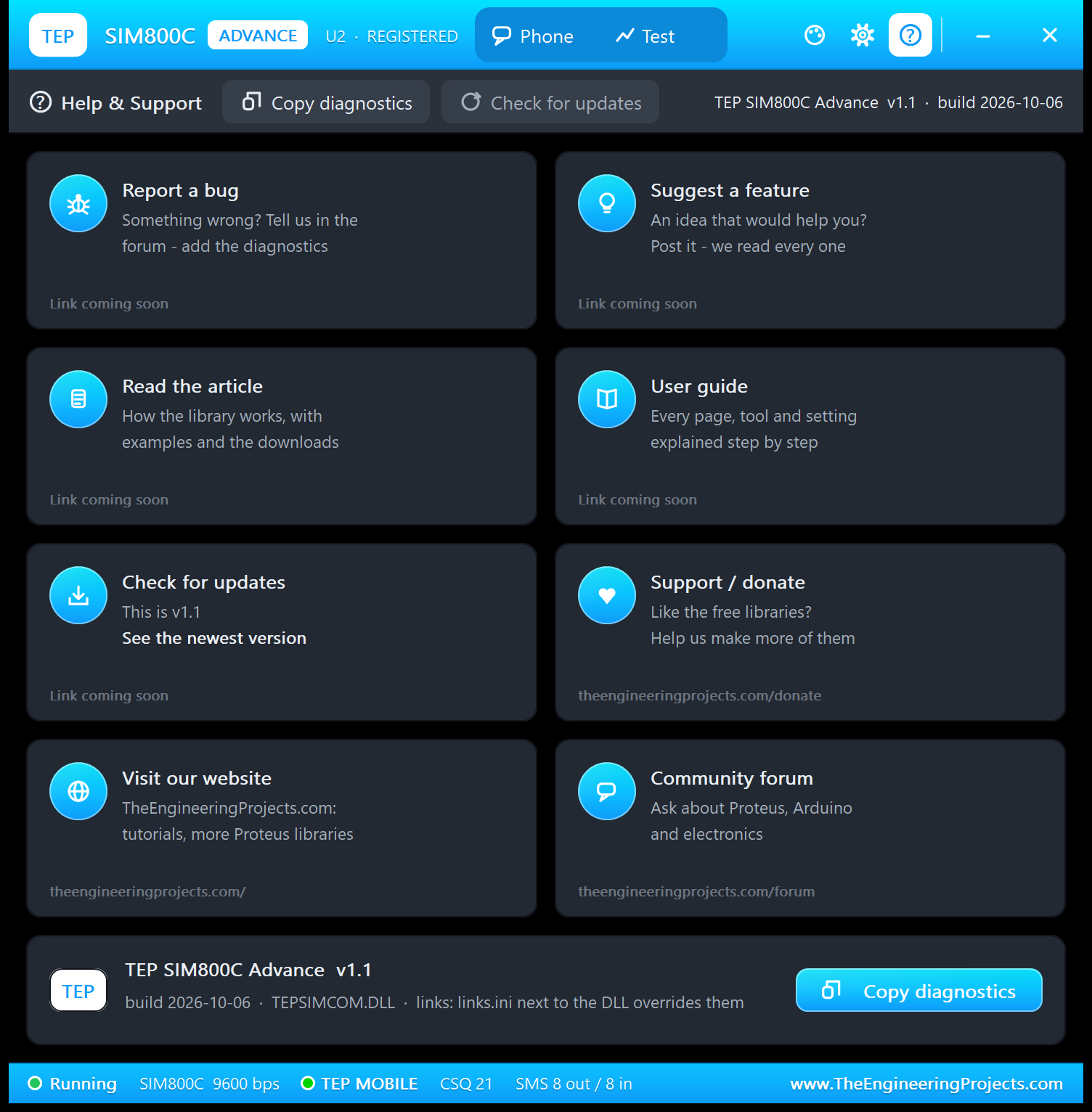
The ? icon opens Help & Support: eight cards (bug report, feature request, article, user guide, updates, donate, website, forum) and Copy diagnostics for a bug report. Cards whose link is not published yet say "Link coming soon"; a links.ini file next to the DLL can change them.
Arduino SIM800C Proteus Simulation
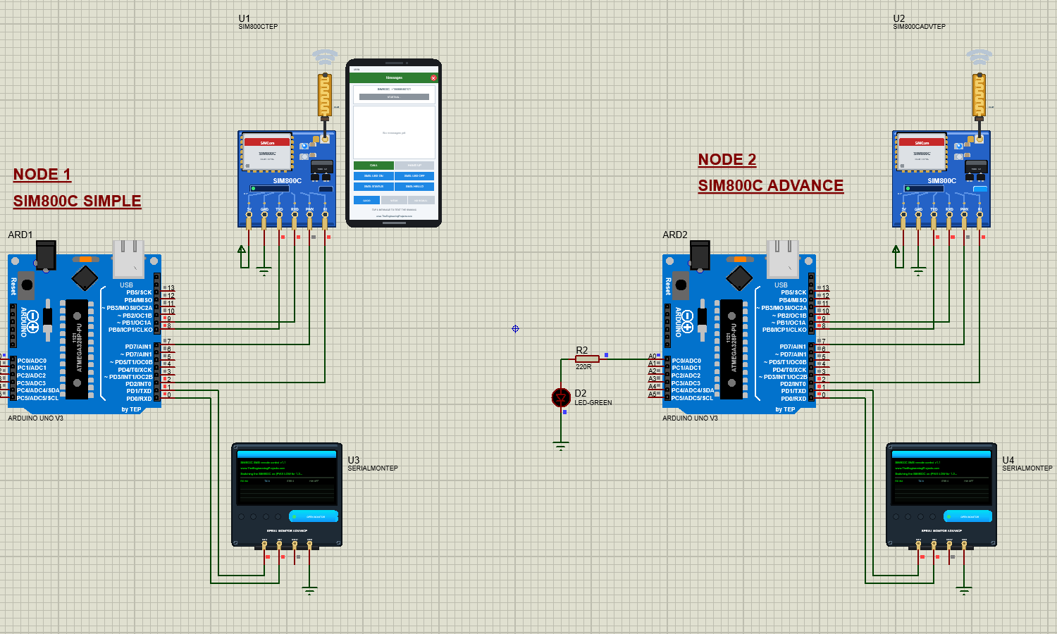
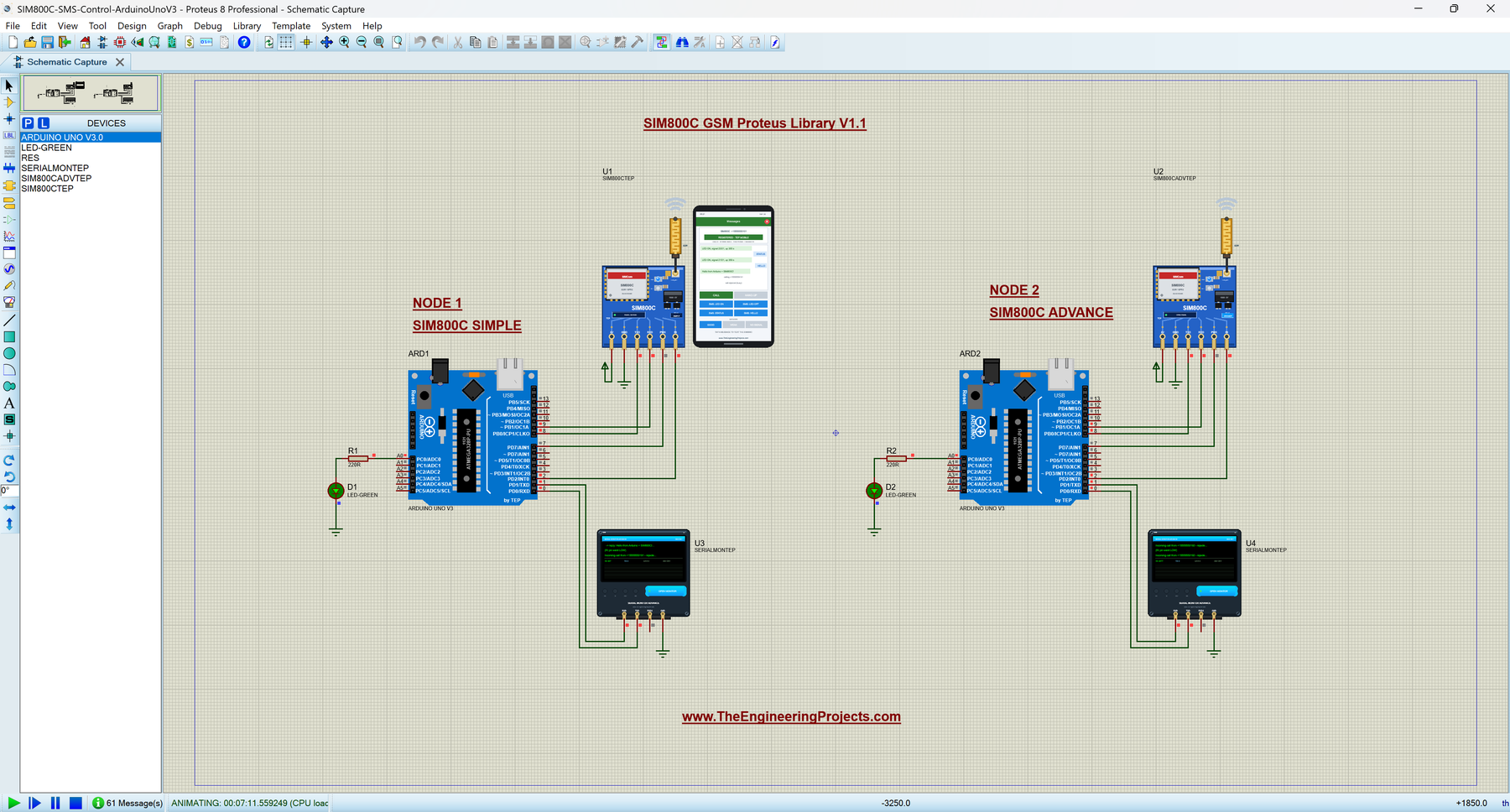
Open SIM800C-SMS-Control-ArduinoUnoV3.pdsprj from the Proteus Simulation folder. It has two Arduino UNOs from our Arduino Library for Proteus V3.0, both running SIM800C_SMS_Control.hex:
- NODE 1: UNO 1 (ARD1) with the SIM800C Simple (U1, +15555550101, its phone +15555550191), LED D1 and Serial Monitor U3.
- NODE 2: UNO 2 (ARD2) with the SIM800C Advance (U2, +15555550102, its phone +15555550192), LED D2 and Serial Monitor U4.
Wiring
| From | To | Why |
|---|---|---|
| SIM800C 5V / GND | Supply / ground | Power |
| SIM800C TXD | Arduino D8 | AltSoftSerial RX: answers and URCs |
| SIM800C RXD | Arduino D9 | AltSoftSerial TX: AT commands |
| SIM800C PWX | Arduino D7 | The power key (pulled LOW for 1.2 s, then released) |
| SIM800C RI | Arduino D2 | INT0 interrupt for calls and new SMS |
| LED + 220 Ω | A0 to GND | The LED switched by SMS |
| Serial Monitor RXD / TXD | Arduino D1 / D0 | Shows what the Arduino prints, sends what you type |
| Serial Monitor GND | Ground | Common ground (RXD2 is not used in this demo) |
Want to know more about these pins? Read our Introduction to Arduino UNO. As with every UART module in Proteus 8.5, the sketch uses AltSoftSerial (Paul Stoffregen, MIT licence) on its fixed pins D8 / D9, because SoftwareSerial needs pin-change interrupts and cannot receive in Proteus 8.5. Keep D10 free while it runs. The external interrupt INT0 on D2 works, which is why RI goes there.
The Arduino Code
setupModule() finds the module (switching it on with PWX if needed, as shown above) and prints its model and firmware. It waits for SMS Ready only if it has just switched the module on or AT+CCALR? says the start-up is not finished, so a reset of the UNO stays fast:
  // start-up messages after the sync: +CPIN: READY, Call Ready, SMS Ready (AT+CCALR? = 1: already past them)
  const bool ready = !switchedOn && command("AT+CCALR?", "+CCALR:", answer, sizeof(answer)) && answer[8] == '1';
  if (!ready) {
    Serial.print(F("Waiting for SMS Ready... "));
    Serial.println(waitFor("SMS Ready", 10000) ? F("ok") : F("not seen, continuing"));
  }
Then it puts the SIM800C in the mode the rest of the sketch needs:
  command("ATE0");                     // no echo
  command("AT+CMEE=2");                // errors as text
  command("AT+CMGF=1");                // SMS in text mode
  command("AT+CNMI=2,2,0,0,0");        // print new SMS directly (+CMT:)
  command("AT+CLIP=1");                // show the caller's number (+CLIP:)
The RI pin gets an interrupt on its falling edge; the interrupt only sets a flag, and loop() prints "(RI pin went LOW)":
  pinMode(RI_PIN, INPUT_PULLUP);
  attachInterrupt(digitalPinToInterrupt(RI_PIN), onRing, FALLING);
Every SMS arrives as a +CMT: line followed by the text, every call as RING plus a +CLIP: line. onLine() notes them; loop() then switches the LED and replies by SMS, or prints the caller and rejects the call with ATH:
  } else if (!strncmp(s, "+CMT:", 5)) {
    quoted(s, smsFrom, sizeof(smsFrom));
    smsTextNext = true;
  } else if (!strncmp(s, "+CLIP:", 6)) {
    quoted(s, caller, sizeof(caller));
    callWaiting = true;
New in v1.1: every 30 s, the sketch asks AT+CMGF?. A wrong answer means the module has restarted and lost its settings; no answer means it may even be off after a power-down. Either way, setupModule(true) runs again and presses PWX only if the module stays silent:
  // every 30 s: is the module still set up? (a restart clears its settings; a power-down switches it off)
  if (restarted || millis() - lastCheck > CHECK_EVERY) {
    char answer[24];
    const bool ok = command("AT+CMGF?", "+CMGF:", answer, sizeof(answer), 1000);
    if (restarted || !ok || answer[7] != '1') {
      restarted = false;
      Serial.println(ok ? F("The SIM800C restarted (settings lost) - setting it up again")
                        : F("No answer from the SIM800C (restarted or off) - setting it up again"));
      if (setupModule(true)) printHelp();
If you change the sketch, load the new HEX file into both UNOs; see How to get the HEX file from Arduino. New to Arduino? Start with our Arduino Tutorial for Beginners.
Serial Monitor Commands
| Command | What it does |
|---|---|
| AT... | Sent to the SIM800C as typed; the answer lines are printed with " < " until OK / ERROR |
| STATUS | LED, signal (CSQ), registered or not, operator, up time |
| TEXT <message> | An SMS to the last number that texted the module |
| HELP | The command list |
How to Run the Demo
- Open the project, with the .hex file and both DLLs beside it, and press Run. Both Serial Monitors open at 9600 baud, and so does U2's pop-up.
- Watch the boards start OFF and the sketches pulse PWX; after about 12 s both monitors show the command list.
- Tap SMS: LED ON on U1's phone and watch LED D1 and U3. Try CALL, and NO SIGNAL + an SMS + GOOD.
- In U2's pop-up, open the Test tab and run the four tools while you watch U4.
Simulation Results
The Serial Monitor in Its Simple Interface
Both monitors in this demo run in the Simple interface of our TEP Serial Monitor, and every screenshot here shows them that way. It keeps only the log, the send box and one slim toolbar row: baud rate, follow, pause, search and clear. The header, the quick buttons and the status bar are hidden, so the window stays small next to your schematic.
- Switch to it: right-click the log and choose Simple interface, or press Ctrl+Shift+U.
- Back to the full view: click the corner button (the expand arrows at the top right), press Esc or Ctrl+Shift+U, or right-click and choose Full interface.
- Your choice is remembered.
In the Simple interface, type commands such as AT+CSQ in the send box and press Enter; the quick buttons come back with the full view. Read all about the monitor in TEP Serial Monitor Advance for Proteus.
What the Monitors Show
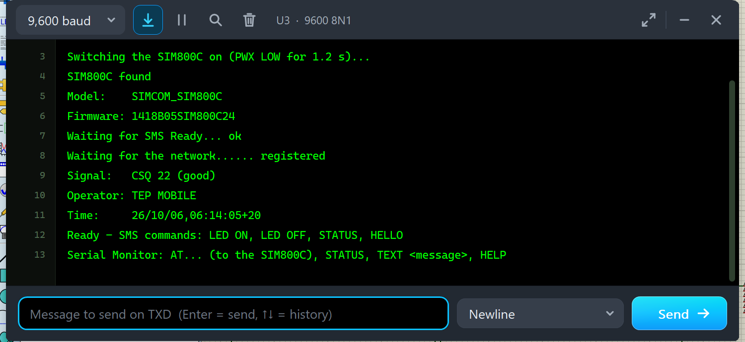
After Run, each monitor prints the start-up. Here is U3 in my Proteus run, from the PWX pulse to the command list:
Switching the SIM800C on (PWX LOW for 1.2 s)...
SIM800C found
Model:    SIMCOM_SIM800C
Firmware: 1418B05SIM800C24
Waiting for SMS Ready... ok
Waiting for the network...... registered
Signal:   CSQ 22 (good)
Operator: TEP MOBILE
Time:     26/10/06,06:14:05+20
Ready - SMS commands: LED ON, LED OFF, STATUS, HELLO
Serial Monitor: AT... (to the SIM800C), STATUS, TEXT <message>, HELP
Line by line: the sketch pressed PWX, found the module with "AT", read its model (AT+CGMM) and firmware (AT+CGMR), waited for SMS Ready and polled AT+CREG? once per second (the dots) until the module registered. Then it read the signal, the operator and the network clock: 26/10/06,06:14:05+20 is 6 Oct 2026 at 06:14:05, and +20 is the time zone in quarter hours (UTC+5). Lines 1 and 2 are the sketch's name and our website.
Then I tapped the SMS buttons and CALL on U1's phone, and U3 went on like this:
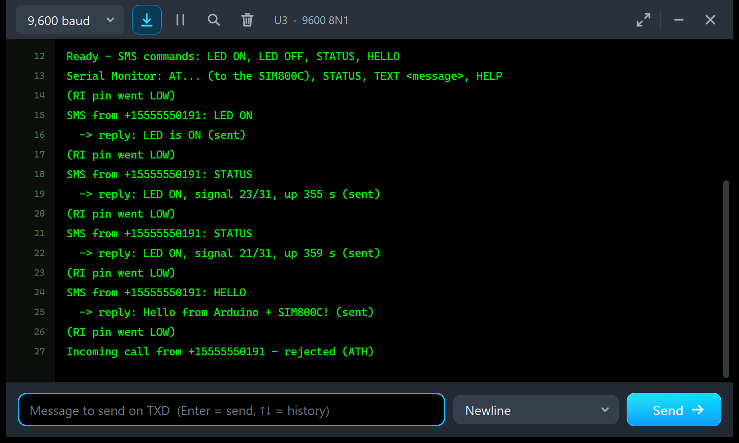
Every SMS is announced by "(RI pin went LOW)", the INT0 interrupt of the 120 ms RI pulse; the call pulls RI LOW too. U4 tells the same story for the pop-up's phone:
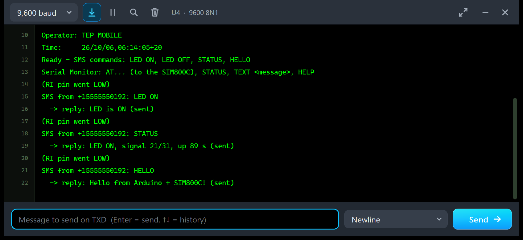
The README listing (PC test) also shows what the AT+CSQ quick button prints: the command, and the module's answer passed through by the sketch:
> AT+CSQ
  < +CSQ: 22,0
  < OK
SIM800C AT Commands Supported
| Group | Commands |
|---|---|
| General | AT, ATE0/1, ATI (SIM800 R14.18), ATV, ATQ, ATZ, AT&W, ATS<n>, AT+CGMI, +CGMM (SIMCOM_SIM800C), +CGMR (Revision:1418B05SIM800C24), +GSV, +CGSN, +CCID, +CIMI, +CPIN?, +CFUN (0, 1, 4; 1,1 restarts), +CPOWD (1 = NORMAL POWER DOWN, 0 = urgent off), +CPAS, +CBC, +CCLK, +CLTS, +CIURC, +CCALR?, +CFGRI?, +CBAND, +CMEE (0 / 1 / 2), +IPR (0 = auto-baud; fixed 1200 - 460800); several commands on one line |
| Network | AT+CREG (0 / 1 / 2 and ?), +CSQ, +COPS? / =?, +CGATT?, +CUSD=1,"*123#" (a balance message) |
| SMS (text mode) | AT+CMGF=1, +CSCS, +CSCA?, +CNMI=2,1 (+CMTI) or 2,2 (+CMT), +CMGS with the "> " prompt, Ctrl+Z sends, ESC cancels, +CMGR, +CMGL, +CMGD, +CMGDA, +CPMS (30 messages) |
| Calls | ATD+number; (NO CARRIER / BUSY / NO ANSWER after 30 s), ATA, ATH, AT+CLIP=1, AT+CLCC |
| Unknown | ERROR, and the command is named in the Simulation Log |
Two SIM800C details: AT+CSQ? (with a question mark) answers ERROR, as in the AT manual; use AT+CSQ. Without network, AT+CMGS fails after 2 s with ERROR, or +CMS ERROR: 331 with AT+CMEE=1.
Troubleshooting
- "No answer from the SIM800C": the HW-537 stays OFF until PWX is held LOW for more than 1 s (the phone says MODULE OFF - HOLD PWX LOW 1 s). Check TXD -> D8, RXD <- D9, AltSoftSerial and "AT" first.
- The SIM800C switched itself off: a PWX pulse longer than 1 s while it runs is NORMAL POWER DOWN. Send "AT" first and pulse PWX only when there is no answer.
- SMS arrive but the sketch sees nothing: send
AT+CMGF=1andAT+CNMI=2,2,0,0,0(the phone shows a tip while the module is in PDU mode). - SEARCHING FOR NETWORK: wait about 3 s after SMS Ready, and check that NETWORK is not on NO SIGNAL.
- No answers after a restart: the module auto-bauds again and has lost its settings; send "AT" and set it up again.
- Garbage characters at power-up: the sync bytes, sent at 115200 bps; normal.
- No phone, pop-up or monitor:
TEPSIMCOM.DLLorTEPSERIALMON.DLLis missing from MODELS and the project folder. For the Advance, click OPEN PANEL or turn "Open the panel at Run" back on. - The red X does not close the phone: the design still holds the v1.0 symbol; replace TEPSIM800C.LIB, delete TEPSIM800C.IDX and re-pick the part.
Things to Know Before Using a Real SIM800C
- Power: the chip draws up to 2 A peaks in its transmit bursts. Feed the HW-537's 5V pin from a 5 V supply that can deliver 2 A peaks, not the Arduino's 5V pin, with a common GND.
- V_TTL: tie it to the Arduino's logic supply (5 V on an UNO); it is the reference of the TXD / RXD level shifter. RI is probably not level shifted (unverified), so check its level.
- Bare module: a SIM800C without the shifter has 2.8 V logic. Put 10 k from D9 to RXD and 12 k from RXD to GND (about 2.7 V), and power it from 3.4 - 4.4 V.
- PWX: never drive it HIGH from a 5 V pin; pull it LOW and release it, like the sketch.
- 2G only: the SIM800C does not work where the 2G network has been switched off.
- Start-up time: the model follows the data sheet's minimums; on a poor network, a real module can take much longer to reach Call Ready.
Limitations of the Simulation
- Not modelled: GPRS / TCP / HTTP, PDU-mode SMS, audio, DTMF, Bluetooth / TTS, the SIM phone book, voltage and temperature warnings, the supply current and brown-outs, a missing SIM, DTR and sleep modes, and the pins V_TTL, VBAT, DTR, VRTC and audio.
- The network, operator, SMS centre and USSD reply are simulated; no real SIM is involved.
- The model is our own implementation, written from SIMCom's published AT Command Manual and SIM800C Hardware Design; it contains no SIMCom firmware.
- Tested in Proteus 8.5 on 6 Oct 2026 (the demo and every Proteus screenshot here; the two PC renders are labelled) and with 1,667 automatic checks on the PC; Proteus 7 is not supported.
Looking for another GSM library for Proteus? For the red board, see our SIM800L Library for Proteus; for GPS + GSM, our SIM808 Library for Proteus; and for the SIM900A mini board, our SIM900A Library for Proteus, which uses the same model file. Need Wi-Fi instead? Try our ESP-01 Library for Proteus.
So, that was all about the SIM800C GSM Library for Proteus V1.1. I hope the power key, the virtual phone and the test tools make the SIM800C much easier to understand, so your sketch works the first time you wire a real HW-537 board. If you use the SIM800C Library for Proteus in a project, please share your feedback in the comments or in our forum, and if you have any questions, ask in the comments and I will help you out. Till the next tutorial, take care and have fun!