Hello friends, I hope you all are doing great. Today, I am going to share the new Push Button Library for Proteus. A push button looks like the simplest part in electronics: press it and the circuit closes, let go and it opens. Yet it has fooled nearly everyone who has ever tried to count presses with an Arduino, because a real switch does not close cleanly. It bounces.
Push Button Library for Proteus
Latest version: V1.0 (November 2026, this tutorial)
Other component libraries: C945 Transistor · PC817 Optocoupler · Relay Module · Resistor · 5 mm LED · Designer Colour LED · Active Buzzer · Electrolytic Capacitor · Ceramic Capacitor · Tantalum Capacitor · Film Capacitor · 1N4007 Diode · Zener Diode · Schottky Diode · Supercapacitor · Photodiode · RGB LED · Bridge Rectifier · Flashing LED · Bi-Colour LED · SMD LED · Slide Switch · Toggle Switch · Rocker Switch · Micro Limit Switch · Emergency Stop Switch · SMD Resistor · Power Resistor · Resistor Network · Potentiometer · Trimmer Potentiometer · Slide Potentiometer · NTC Thermistor · DIP Switch · Fuse · Passive Buzzer · Mini Speaker · 7-Segment Display · LED Bar Graph · IR / UV LED · Small Transistors · TIP122 Darlington · N-MOSFET · P-MOSFET · PC817 Optocoupler · Filament Bulb · Power LED · Voltage Regulator · SCR and TRIAC · Inductor · Toroid Inductor · Crystal
Helping Tools
- Serial Monitor Advance: a serial terminal window for the UART of your board
- Serial Monitor Expert: the serial monitor with extra debugging tools
- LCD Library for Proteus V3.0: 16x2, 20x4 and I2C LCDs to show your readings
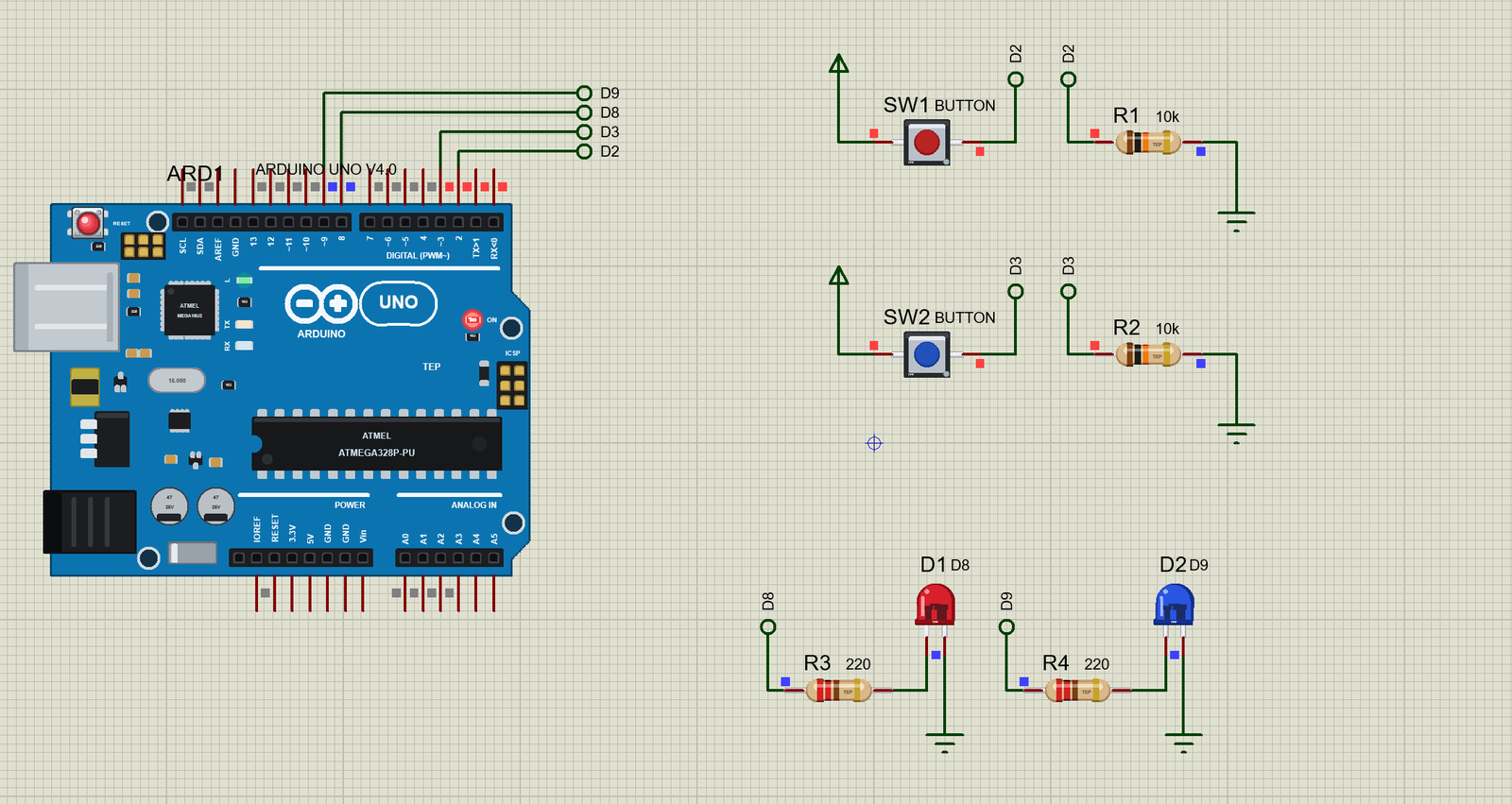
So we built a button that behaves like a real one. It is the small 6 mm tactile switch you find on every board, drawn to true scale, in six cap colours. Click the cap and it goes down. And inside, the contact chatters for a few milliseconds just like the real thing, while the pop-up counts every edge. You can finally see what your sketch is up against.
NOTICE: Our team has put a lot of effort into these small parts: the bodies, the animation and the pop-ups are all our own design, and you get them free. Your feedback is the fuel that keeps us going, so please tell us what you think in the comments below or in the Push Button board of our forum. And if our free libraries help you, you can buy us a coffee. So, let's get started with the Push Button Library for Proteus:
What is a Tactile Push Button?
A tactile switch is a small momentary button. It is closed only while you press it, and a tiny metal dome inside gives that little click you can feel, which is where the name comes from. The common size is 6 x 6 mm. It has four legs, joined in two pairs, so it can sit across the gap in a breadboard. Pressing the cap flexes the dome down onto the contacts, and that joins the two pairs.
| Feature | The real part | In the library |
|---|---|---|
| Size | 6 x 6 mm body | 250 thou square, true scale |
| Contact resistance | about 0.1 ohm | 0.1 ohm, a property |
| Open | many megohms | 100 Mohm |
| Bounce | a few milliseconds | 5 ms, a property |
| Current | about 50 mA | the Check page warns over it |
Where Tactile Switches Are Used
Look closely at almost any small product and you will find one. They sit behind the buttons of TV remotes, printers, car keys, kitchen scales and game controllers. The plastic button you press is usually just a cover, and the small switch underneath does the real work. Every Arduino has one too: the RESET button on the board is a tactile switch. They are popular because they are cheap, small and easy to solder, and because the click tells your finger that the press has landed.
A Pin Must Never Float
Here is the first trap. When the button is open, what voltage does the Arduino pin see? If nothing else is connected, the answer is nobody knows. The pin is floating, and it picks up noise from everything around it, so it reads HIGH and LOW at random. It needs a resistor to hold it at a known level while the button is open.
| Way of wiring | Open | Pressed | How |
|---|---|---|---|
| Pull-down | LOW | HIGH | button to +5V, 10k from the pin to GND |
| Pull-up | HIGH | LOW | button to GND, 10k from the pin to +5V |
| Built-in pull-up | HIGH | LOW | button to GND, pinMode(pin, INPUT_PULLUP) |
Our demo uses pull-downs, because a HIGH press is the easiest to think about. The resistors are the real-looking parts from our Resistor Library for Proteus.
What is Contact Bounce?
Now the second trap. When two metal contacts come together, they do not simply stay together. They strike, spring apart, strike again, and settle a few milliseconds later. Your finger cannot feel it, but an Arduino reads its pins millions of times a second. To the sketch, one press looks like several very fast presses. It happens on the way out too.
This is contact bounce, and it is why a simple counter jumps by three or nine when you expected one. Our model does the same thing: each change of the contact makes a burst of edges over about 5 ms, in an irregular pattern, so your sketch sees what it would see on a real board.
The size of the bounce depends on the switch. A new tactile switch may settle in a millisecond or two, while a large toggle switch or a worn contact can chatter for ten or more. A slow program will often miss it completely, which is why a sketch can seem fine for months, and then start to misbehave once it is made faster or moved to an interrupt.
What is Debouncing?
The cure is debouncing: ignore the input until it has stopped changing. In a sketch, you note the time of every change, and you only believe the new value once it has stayed the same for a while, about 20 ms. That is long enough for any bounce to die away, and far too short for a person to notice. In hardware, a small capacitor across the switch does a similar job.
Features of the Push Button Library for Proteus
- The real look, at true scale: the black body, the metal plate and a round cap, with our small TEP signature.
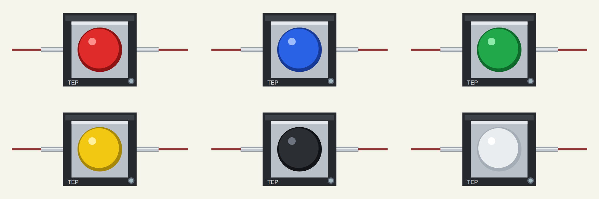
- Six cap colours: red, blue, green, yellow, black and white.
- Click to press: the cap goes down while the mouse is down, as a real button would.
- Real contact bounce: a burst of edges on every change, for as long as you set.
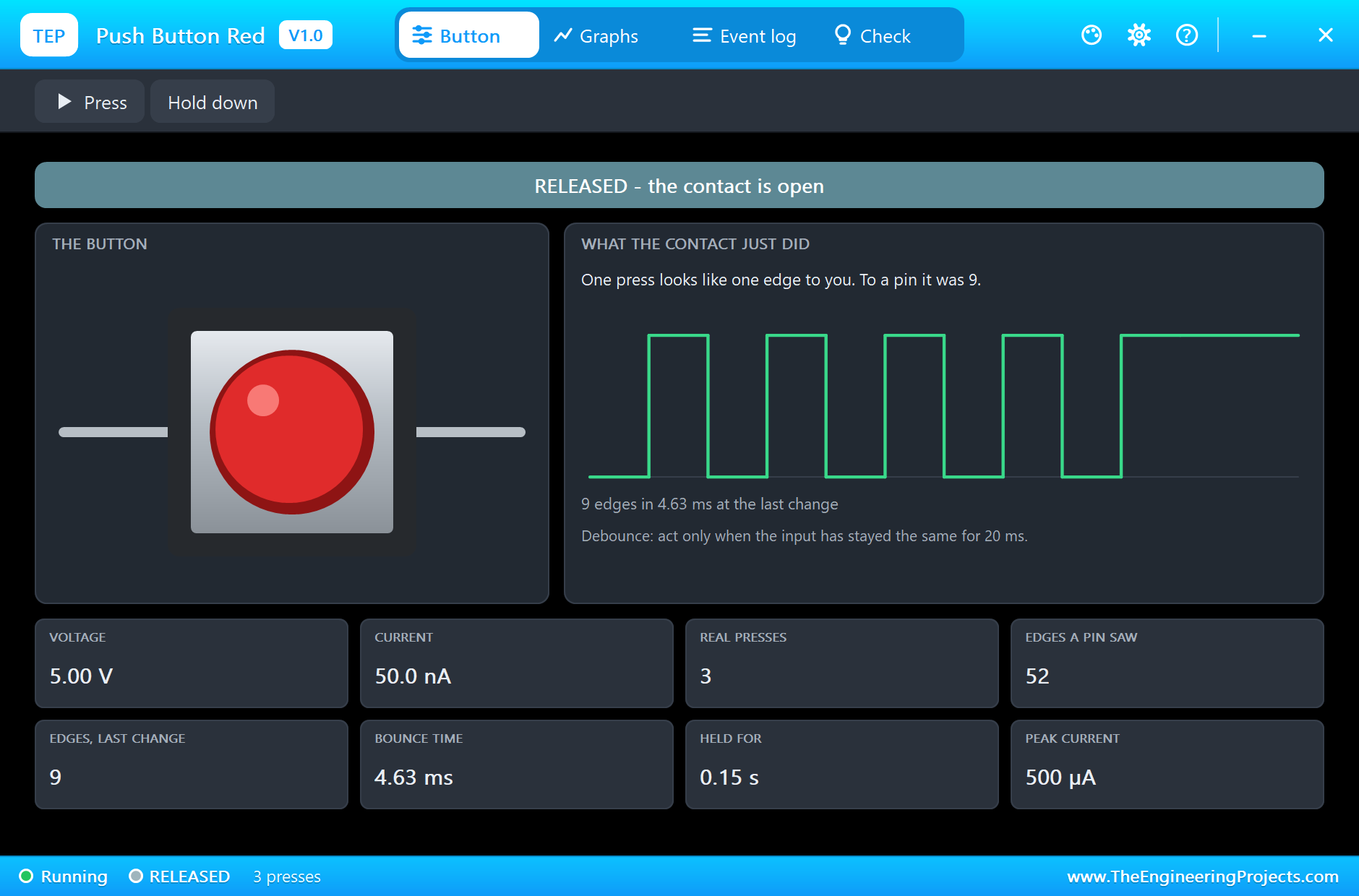
- The truth on one page: the pop-up counts real presses against the edges a pin saw, and draws the last bounce.
- A true analog part: a small resistance closed and 100 Mohm open, so it works with any circuit, not only logic.
- A complete package: about 1.8 MB with the library, our Arduino UNO V4.0, the demo's resistors and LEDs and the demo, without the source code of the models.
The Push Button in Proteus
The six devices are in TEPBUTTON.LIB, under Switches and Relays, Switches, with the prefix SW. Search BUTTON in Pick Devices and look for the TEP names. They all run on one model, TEPBUTTON.DLL. The real part's two pairs of legs are one pin each here, 1 and 2.
| Cap colour | Device |
|---|---|
| Red | BUTTONREDTEP |
| Blue | BUTTONBLUETEP |
| Green | BUTTONGREENTEP |
| Yellow | BUTTONYELLOWTEP |
| Black | BUTTONBLACKTEP |
| White | BUTTONWHITETEP |
Press It, or Open It
A click on the cap presses the button, and it stays down for as long as you hold the mouse. A click on the small dot in the corner of the body opens the pop-up. Both work only while the simulation runs.
The Properties
| Property | What it does |
|---|---|
| Contact resistance, ohm | the closed contact, 0.1 ohm by default |
| Contact bounce, ms | how long it chatters, 5 ms by default; 0 is a perfect contact |
Download Push Button Library for Proteus
Click the button below to download Push-Button-Library-for-Proteus-v1.0.zip (about 1.8 MB, without the source code of the models):
Push Button Library for Proteus V1.0- README.txt: installation, the demo, the properties, troubleshooting and the limits.
- Proteus Library Files:
TEPBUTTON.LIB,TEPRESISTOR.LIB,TEPLED5MM.LIBand ourArduinoV4TEP.LIB. - Proteus Model Files:
TEPBUTTON.DLL,TEPRESISTOR.DLL,TEPLED5MM.DLLandTEPARDUINO.DLL. - Arduino Code: the demo sketch.
- Proteus Simulation: the demo project, its HEX file and copies of the DLLs.
No Proteus yet? Read How to Download and Install Proteus 7 and 8. New to libraries? Follow How to Install a New Library in Proteus.
How to Install Push Button Library for Proteus
- Close Proteus and extract the whole zip file, for example to your Desktop.
- Copy the files from Proteus Library Files into the LIBRARY folder of Proteus.
- Copy the files from Proteus Model Files into the MODELS folder.
- Delete
TEPBUTTON.IDXfrom the LIBRARY folder if it is there. - Start Proteus, press P and search for BUTTON.
Demo: The Same Job, Two Ways
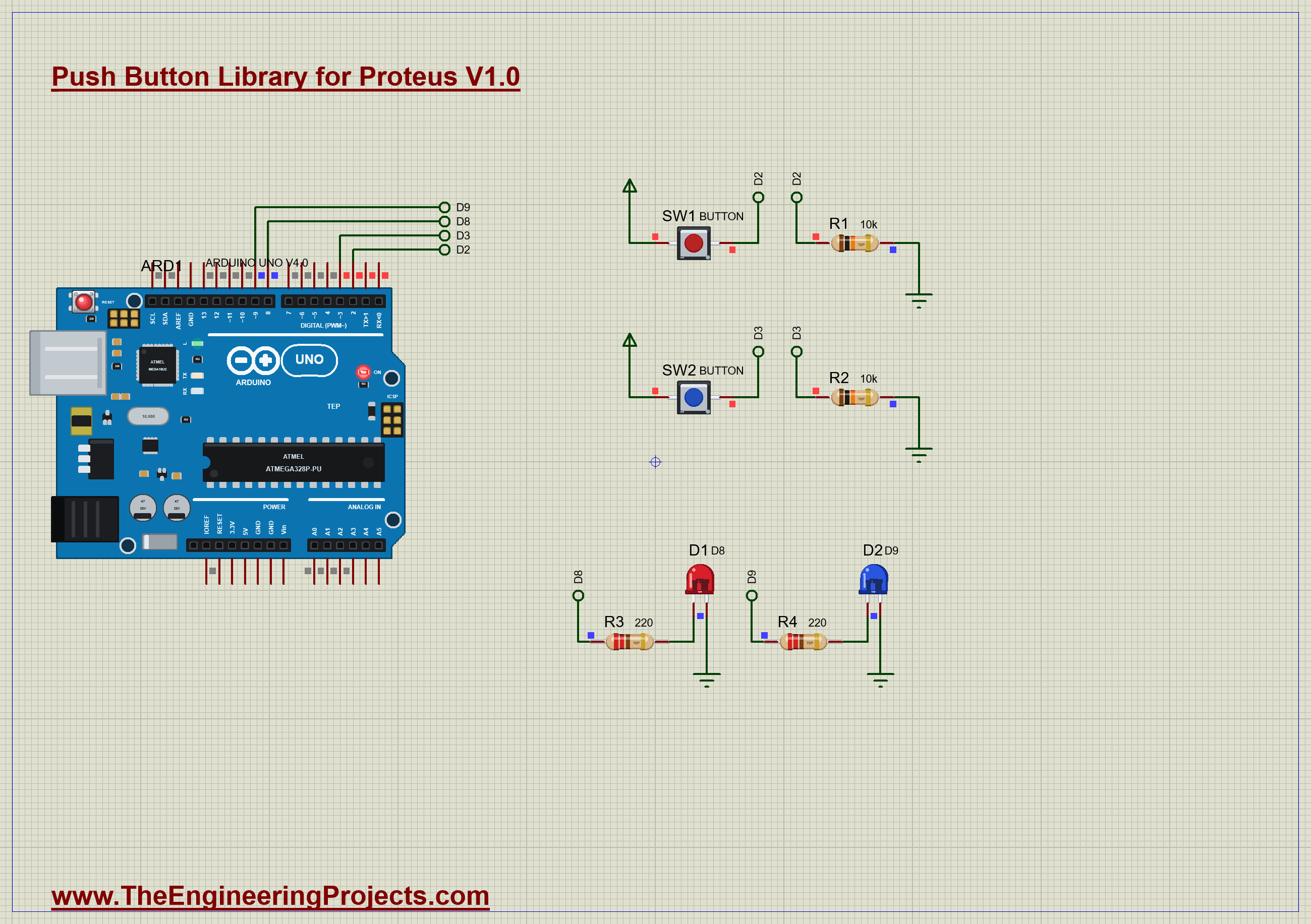
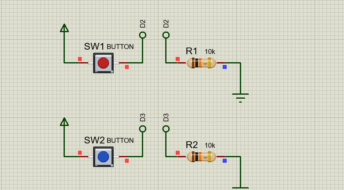
The best way to understand bounce is to see it side by side. The demo has two buttons doing the same job: each one toggles an LED. SW1 is counted by an interrupt with no debounce. SW2 is read with a 20 ms debounce. Open Push-Button-Debounce-ArduinoUnoV4.pdsprj. It runs on our Arduino UNO Library for Proteus V4.0, with its built-in monitor, the same window as our TEP Serial Monitor Advance for Proteus. The LEDs come from our 5 mm LED Library for Proteus.
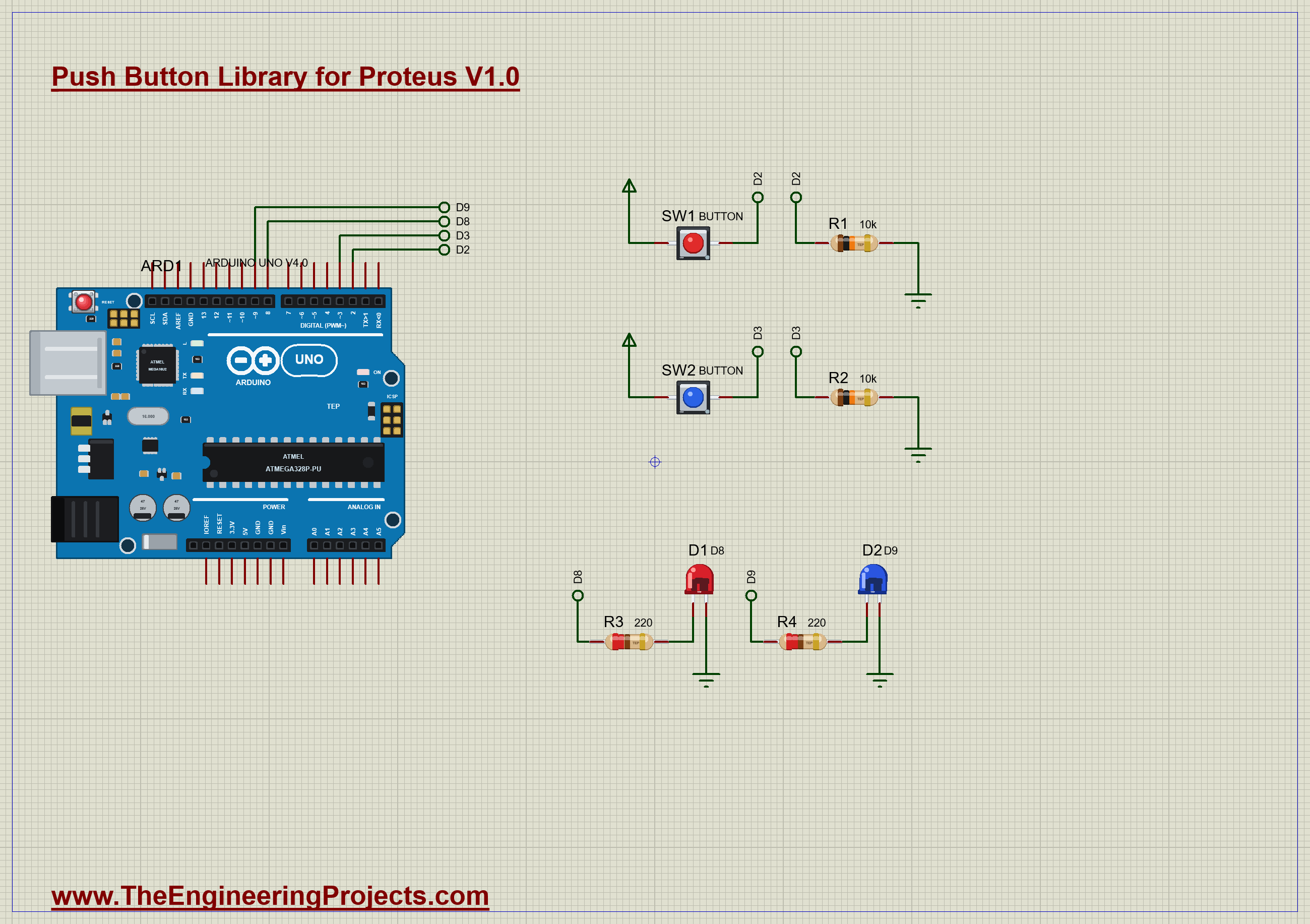
| Part | Connection | Job |
|---|---|---|
| SW1, red | +5V to D2, R1 10k to GND | counted raw, by an interrupt |
| SW2, blue | +5V to D3, R2 10k to GND | read with a debounce |
| D1, red | D8 through 220 ohm | SW1's LED |
| D2, blue | D9 through 220 ohm | SW2's LED |
The Raw Button
An interrupt runs the moment a pin changes, so it catches every edge. That makes it a perfect way to show the problem. This little function counts each rising edge and flips the LED:
void rawButton() {
  rawEdges++;
  rawLed = !rawLed;
  digitalWrite(RAW_LED, rawLed);
}
If a press makes nine edges, the LED flips nine times in five milliseconds, and it ends up in whichever state the last edge left it. To you it looks random, as if the button only works some of the time.
This does not mean that interrupts are bad. They are the right tool for fast signals, such as an encoder or a pulse from a sensor, where a clean edge really does mean something. A human finger is different. It is very slow and its signal is very dirty, so a button is usually better read in the main loop, a little at a time, as the next part of the sketch does.
The Debounced Button
SW2 takes its time. Each time the reading changes, the sketch notes when. A new state only counts once it has lasted 20 ms, so the whole burst of bounces counts for nothing, and a press is a press:
  bool reading = digitalRead(CLEAN_BUTTON);
  if (reading != lastReading) {
    lastChange = millis();
    lastReading = reading;
  }
  if (millis() - lastChange >= DEBOUNCE_MS && reading != stableState) {
    stableState = reading;
Notice that nothing here uses delay(). The sketch never stops, so it can look after other things at the same time. That is the pattern to copy into your own projects.
Run the Demo
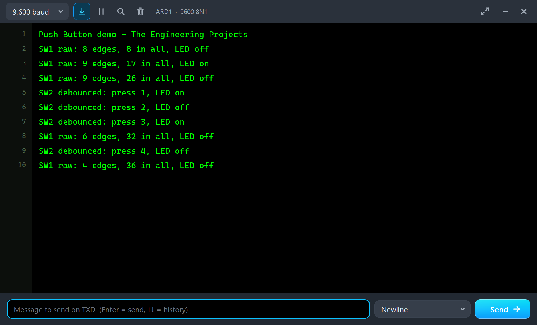
Press Run and the monitor opens. Now click the cap of the red button, SW1, a few times. The red LED toggles sometimes, and sometimes seems to ignore you. The monitor shows why:
SW1 raw: 8 edges, 8 in all, LED off
SW1 raw: 9 edges, 17 in all, LED on
SW1 raw: 9 edges, 26 in all, LED off
Three presses, twenty-six edges. Now open the pop-up by clicking the dot in the corner of SW1. The Button tab tells the same story: three real presses, but many more edges at the pin. The picture shows the last bounce as a pin saw it:
Now the Debounced One
Click the blue button, SW2, the same number of times. Its contact bounces just as badly, and its pop-up counts just as many edges. But look at the monitor. One press, one line, and the blue LED toggles every time:
SW2 debounced: press 1, LED on
SW2 debounced: press 2, LED off
SW2 debounced: press 3, LED on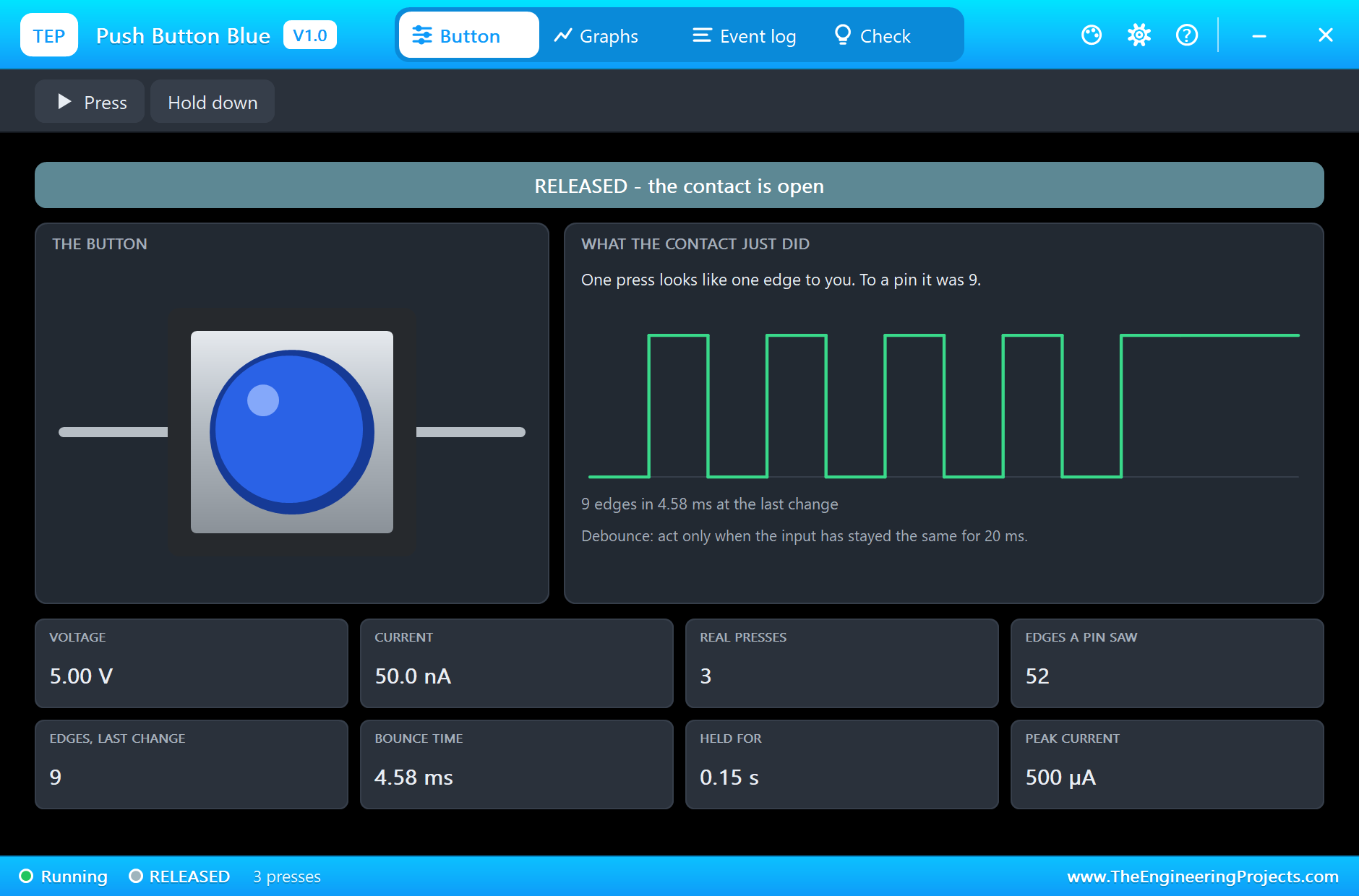
Hold It Down
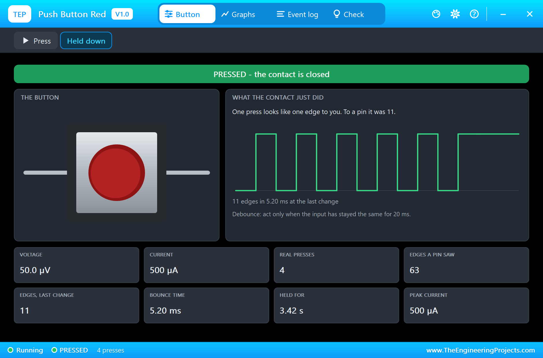
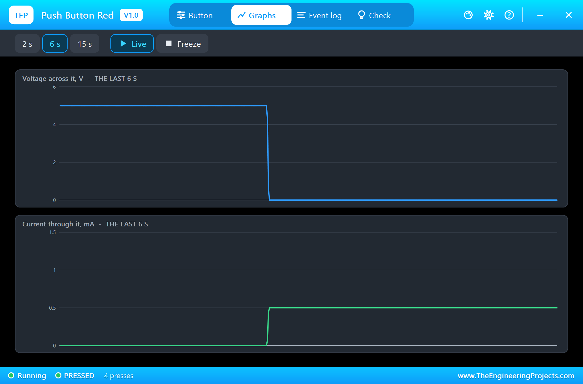
The pop-up also has a Hold down chip, which keeps the button pressed until you click it again. Press the chips on both buttons and the banner changes to PRESSED. Here is the complete circuit, truly running, with both buttons held and the current flowing through the pull-downs:
The Graphs and the Log
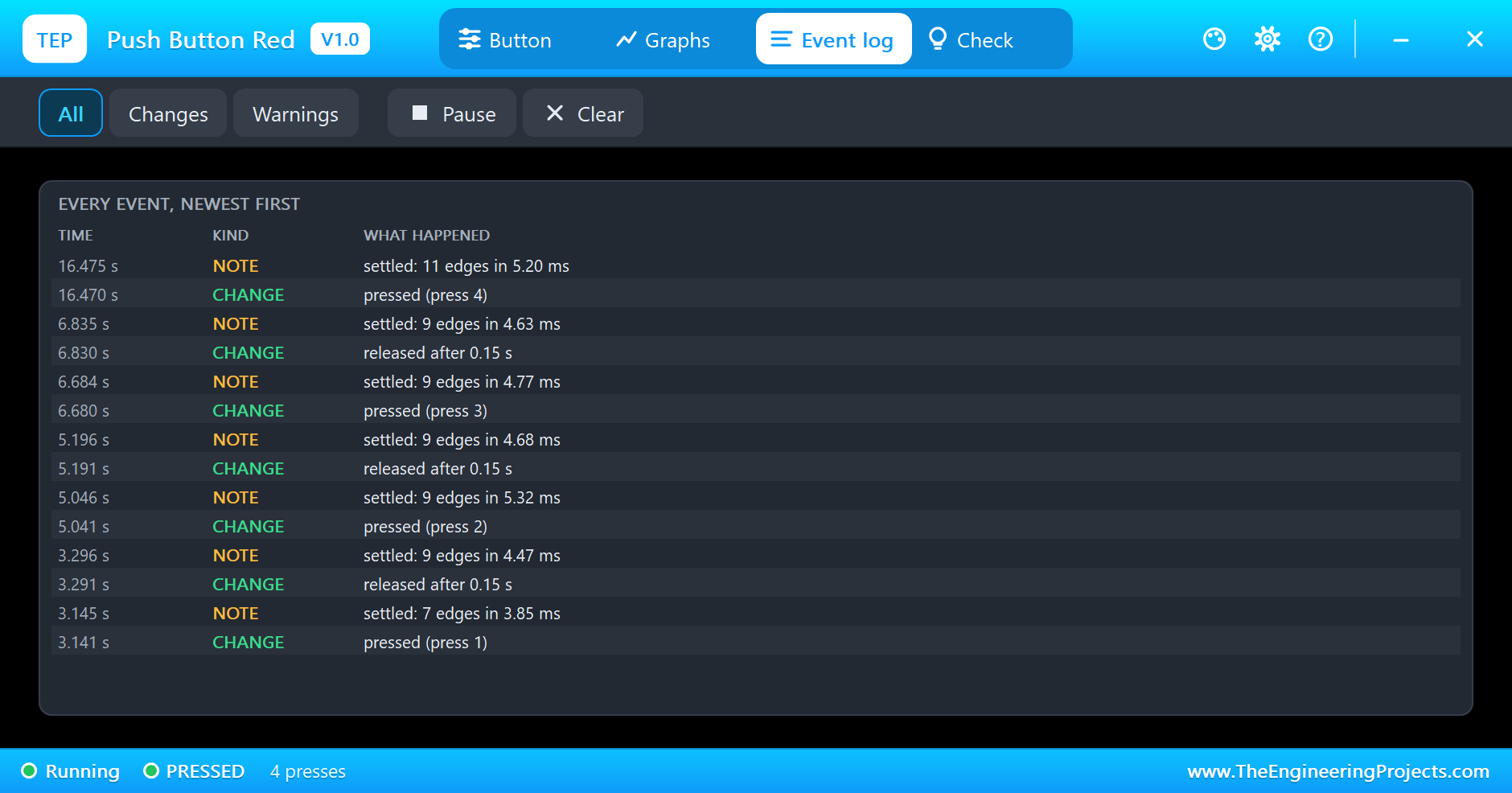
The Graphs tab shows the voltage and the current over the last few seconds. A bounce is far too quick for a graph on this scale, which is exactly why the Button tab draws it for you. The Event log writes down each press, each release, and how each one settled:
The Check Page
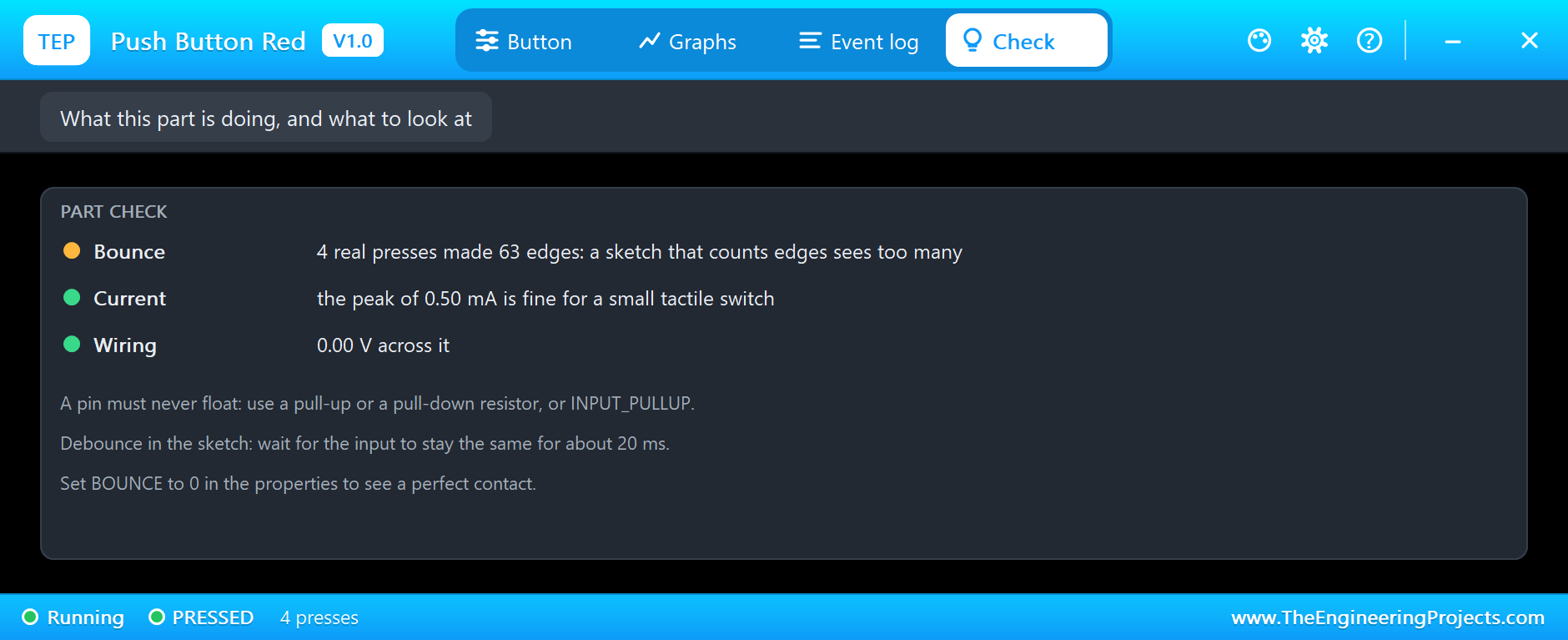
The Check page reads the results like a friend looking over your shoulder. It compares the presses with the edges, checks the current against the 50 mA a small switch can carry, and warns you if the button has no voltage across it while open, which often means a floating pin:
Why the Button is an Analog Part
Many switch models in simulators only pass a logic level. Ours is a real resistance in the circuit: 0.1 ohm when closed and 100 Mohm when open. So it works anywhere a real button would. You can put it in series with a battery and a lamp, use it to discharge a capacitor, or join it to a resistor divider. The voltage and the current in the pop-up are worked out by the same solver as the rest of the sheet, so a mistake in your wiring shows up in the numbers just as it would on a multimeter.
Try It Yourself
- Set the bounce property of SW1 to 0, and watch every press give one edge.
- Change
DEBOUNCE_MSto 2 in the sketch, and see the debounce start to fail. - Set the bounce to 20 ms, longer than the sketch waits, and see what happens then.
- Rewire SW2 to GND and use
INPUT_PULLUP. Remember that a press now reads LOW. - Measure how long a press lasts, and print it.
Ideas to Extend the Demo
- Tell a short press from a long one, and do a different job for each.
- Build a reaction timer: light an LED at a random moment, and time the press.
- Use a double click to turn on a mode.
- Add a 100 nF capacitor across SW1, and see how hardware debouncing compares.
Your Own Sketches
The demo sketch is in the zip file, and you can change it in the Arduino IDE. New to Arduino? Start with our Arduino Tutorial for Beginners. Export the compiled binary, and set the UNO's PROGRAM property to the new file. Our guide on How to get the HEX file from Arduino shows you where the file ends up.
Debouncing in Hardware
Software is the cheap answer, but it is not the only one. A capacitor of about 100 nF across the switch, working with the pull-down, slows the edges so the bounces are smoothed away. It costs one more part on every button, and the slow edge that results is not ideal for a logic input, so designs that need it follow it with a Schmitt trigger gate. For a hobby project the sketch is usually the better place to do it, because a change costs nothing. Hardware is worth having when a button feeds an interrupt directly, or when the program is too busy to look at the pin often.
Things to Know Before Using a Real Button
- Never leave a pin floating: use a pull-up, a pull-down or
INPUT_PULLUP. - Bounce gets worse with age: a worn switch can chatter for much longer, so leave a margin.
- Test the legs: the four legs are joined in pairs, and it is easy to fit a switch turned the wrong way, so that it looks always closed.
- Keep the current small: these switches are for signals, not loads. Use a transistor or a relay to switch anything big.
Troubleshooting
- The pin reads at random: it is floating. Add a pull-up or a pull-down.
- One press counts as many: that is contact bounce. Debounce in the sketch, or set the bounce property to 0.
- The pop-up does not open: click the small dot in the corner. A click on the cap presses the button.
- The part is not simulated:
TEPBUTTON.DLLis missing from MODELS and from the project folder.
Limitations of the Simulation
- The two pairs of legs of a real switch are one pin each here.
- The bounce follows a fixed pattern from one run to the next, with a real-looking spread, not a measured one.
- The click you feel, wear and the contact's own capacitance are left out.
- Arduino is a name of Arduino; this library is not made or endorsed by Arduino or Labcenter.
- Tested in Proteus 8.5 in October 2026 (the demo as shipped). Proteus 7 is not supported.
So, that was all about the Push Button Library for Proteus. I hope it helps you see what your sketches are really dealing with, and takes the mystery out of contact bounce. If you have any questions, ask in the comments and I will help you out. Till the next tutorial, take care and have fun!