After reading this post, you will also get the skilled hand on timer interrupt and can understand them more easily. In today's post, I am gonna design a digital clock which will increment after every one second and we will calculate this one second increment using timer interrupt. This clock will be displayed on LCD so if you are not familiar with LCD then must read Interfacing of LCD with 8051 Microcontroller. You can also implement this digital clock with any other microcontroller like Arduino or PIC Microcontroller but today we are gonna implement it on 8051 Microcontroller. The complete simulation along with code is given at the end of this post but my suggestion is to design it on your own so that you get most of it. Use our code and simulation as a guide. So, let's get started with Interrupt based Digital clock with 8051 Microcontroller. :)
Interrupt Based Digital Clock with 8051 Microcontroller
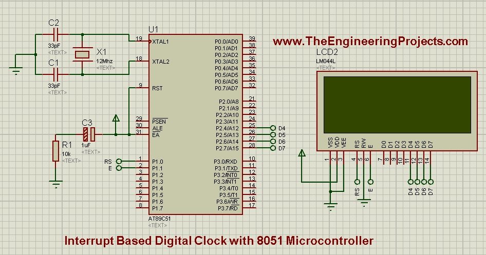
- First of all, design a circuit as shown in below figure:
- Now use the below code and get your hex file. I have designed this code in Keil uvision 3 compiler for 8051 Microcontroller.
#include<reg51.h>

//Function declarations
void cct_init(void);
void delay(int);
void lcdinit(void);
void WriteCommandToLCD(int);
void WriteDataToLCD(char);
void ClearLCDScreen(void);
void InitTimer0(void);
void UpdateTimeCounters(void);
void DisplayTimeToLCD(unsigned int,unsigned int,unsigned int);
void WebsiteLogo();
void writecmd(int);
void writedata(char);

//*******************
//Pin description
/*
P2.4 to P2.7 is data bus
P1.0 is RS
P1.1 is E
*/
//********************

// Defines Pins
sbit RS = P1^0;
sbit E  = P1^1;

// Define Clock variables
unsigned int usecCounter = 0;
unsigned int msCounter   = 0;
unsigned int secCounter  = 0;
unsigned int minCounter  = 0;
unsigned int hrCounter   = 0;


// ***********************************************************
// Main program
//
void main(void)
{
   cct_init();             // Make all ports zero
   lcdinit();              // Initilize LCD
   InitTimer0();           // Start Timer0
  // WebsiteLogo();
	while(1)
	{
		if( msCounter == 0 )                                       // msCounter becomes zero after exact one sec
		{
			DisplayTimeToLCD(hrCounter, minCounter, secCounter);   // Displays time in HH:MM:SS format
		}

		UpdateTimeCounters();                                      // Update sec, min, hours counters
  	}
}
void writecmd(int z)
{
   RS = 0;             // This is command
   P2 = z;             //Data transfer
   E  = 1;             // => E = 1
   delay(150);
   E  = 0;             // => E = 0
   delay(150);
}

void writedata(char t)
{
   RS = 1;             // This is data
   P2 = t;             //Data transfer
   E  = 1;             // => E = 1
   delay(150);
   E  = 0;             // => E = 0
   delay(150);
}

void cct_init(void)
{
	P0 = 0x00;   //not used
	P1 = 0x00;   //not used
	P2 = 0x00;   //used as data port
	P3 = 0x00;   //used for generating E and RS
}


void InitTimer0(void)
{
	TMOD &= 0xF0;    // Clear 4bit field for timer0
	TMOD |= 0x02;    // Set timer0 in mode 2

	TH0 = 0x05;      // 250 usec reloading time
	TL0 = 0x05;      // First time value

	ET0 = 1;         // Enable Timer0 interrupts
	EA  = 1;         // Global interrupt enable

	TR0 = 1;         // Start Timer 0
}


void Timer0_ISR (void) interrupt 1     // It is called after every 250usec
{
	usecCounter = usecCounter + 250;   // Count 250 usec

	if(usecCounter==1000)              // 1000 usec means 1msec
	{
		msCounter++;
		usecCounter = 0;
	}

	TF0 = 0;     // Clear the interrupt flag
}

void WebsiteLogo()
{
   writecmd(0x95);
   writedata('w');                                 //write
   writedata('w');                                 //write
   writedata('w');                                 //write
   writedata('.');                                 //write
   writedata('T');                                 //write
   writedata('h');                                 //write
   writedata('e');                                 //write
   writedata('E');                                 //write
   writedata('n');                                 //write
   writedata('g');                                 //write
   writedata('i');                                 //write
   writedata('n');                                 //write
   writedata('e');                                 //write
   writedata('e');                                 //write
   writedata('r');                                 //write
   writedata('i');                                 //write
   writedata('n');                                 //write
   writedata('g');                                 //write

   writecmd(0xd8);

   writedata('P');                                 //write
   writedata('r');                                 //write
   writedata('o');                                 //write
   writedata('j');                                 //write
   writedata('e');                                 //write
   writedata('c');                                 //write
   writedata('t');                                 //write
   writedata('s');                                 //write
   writedata('.');                                 //write
   writedata('c');                                 //write
   writedata('o');                                 //write
   writedata('m');                                 //write
   writecmd(0x80);
}

void UpdateTimeCounters(void)
{
	if (msCounter==1000)
	{
		secCounter++;
		msCounter=0;
	}

	if(secCounter==60)
	{
		minCounter++;
		secCounter=0;
	}

	if(minCounter==60)
	{
		hrCounter++;
		minCounter=0;
	}

	if(hrCounter==24)
	{
		hrCounter = 0;
	}
}


void DisplayTimeToLCD( unsigned int h, unsigned int m, unsigned int s )   // Displays time in HH:MM:SS format
{
	ClearLCDScreen();      // Move cursor to zero location and clear screen

	// Display Hour
	WriteDataToLCD( (h/10)+0x30 );
	WriteDataToLCD( (h%10)+0x30 );

	//Display ':'
	WriteDataToLCD(':');

	//Display Minutes
	WriteDataToLCD( (m/10)+0x30 );
	WriteDataToLCD( (m%10)+0x30 );

	//Display ':'
	WriteDataToLCD(':');

	//Display Seconds
	WriteDataToLCD( (s/10)+0x30 );
	WriteDataToLCD( (s%10)+0x30 );
}


void delay(int a)
{
   int i;
   for(i=0;i<a;i++);   //null statement
}

void WriteDataToLCD(char t)
{
   RS = 1;             // This is data

   P2 &= 0x0F;		   // Make P2.4 to P2.7 zero
   P2 |= (t&0xF0);     // Write Upper nibble of data

   E  = 1;             // => E = 1
   delay(150);
   E  = 0;             // => E = 0
   delay(150);

   P2 &= 0x0F;		   // Make P2.4 to P2.7 zero
   P2 |= ((t<<4)&0xF0);// Write Lower nibble of data

   E  = 1;             // => E = 1
   delay(150);
   E  = 0;             // => E = 0
   delay(150);
}


void WriteCommandToLCD(int z)
{
   RS = 0;             // This is command

   P2 &= 0x0F;		   // Make P2.4 to P2.7 zero
   P2 |= (z&0xF0);     // Write Upper nibble of data

   E  = 1;             // => E = 1
   delay(150);
   E  = 0;             // => E = 0
   delay(150);

   P2 &= 0x0F;		   // Make P2.4 to P2.7 zero
   P2 |= ((z<<4)&0xF0);// Write Lower nibble of data

   E  = 1;             // => E = 1
   delay(150);
   E  = 0;             // => E = 0
   delay(150);
}

void lcdinit(void)
{
  ///////////// Reset process from datasheet /////////
     delay(15000);

	 P2 &= 0x0F;		   // Make P2.4 to P2.7 zero
	 P2 |= (0x30&0xF0);    // Write 0x3

	 E  = 1;               // => E = 1
	 delay(150);
	 E  = 0;               // => E = 0
	 delay(150);

     delay(4500);

	 P2 &= 0x0F;		   // Make P2.4 to P2.7 zero
	 P2 |= (0x30&0xF0);    // Write 0x3

	 E  = 1;               // => E = 1
	 delay(150);
	 E  = 0;               // => E = 0
	 delay(150);

     delay(300);

	 P2 &= 0x0F;		   // Make P2.4 to P2.7 zero
	 P2 |= (0x30&0xF0);    // Write 0x3

	 E  = 1;               // => E = 1
	 delay(150);
	 E  = 0;               // => E = 0
	 delay(150);

     delay(650);

	 P2 &= 0x0F;		   // Make P2.4 to P2.7 zero
	 P2 |= (0x20&0xF0);    // Write 0x2

	 E  = 1;               // => E = 1
	 delay(150);
	 E  = 0;               // => E = 0
	 delay(150);

	 delay(650);

  /////////////////////////////////////////////////////
   WriteCommandToLCD(0x28);    //function set
   WriteCommandToLCD(0x0c);    //display on,cursor off,blink off
   WriteCommandToLCD(0x01);    //clear display
   WriteCommandToLCD(0x06);    //entry mode, set increment
}

void ClearLCDScreen(void)
{
	WriteCommandToLCD(0x01);   // Clear screen command
	delay(1000);
}
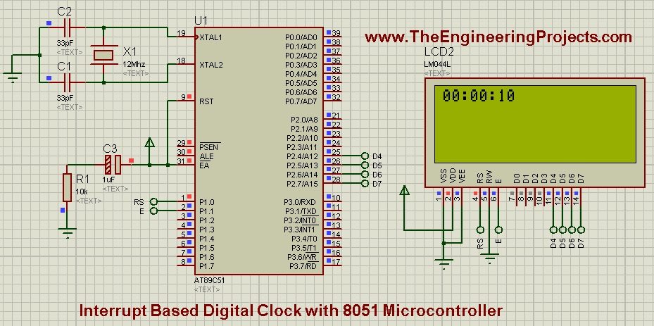
- Now run your simulation and if everything goes fine then you will get results as shown in below figure:

- The above figure is taken after 10 seconds of start of simulation in Proteus ISIS.
- As the simulation keeps on running the clock will also keep on ticking.
- The code is self explanatory but let me explain the interrupt function.
- I have used Timer0 interrupt in this digital Clock.
- The timer interrupt function is incrementing the userCounter variable by 250 which is in micro seconds. So we need 1000us as it will become 1 second. That's why I have placed the check that when userCounter == 1000 then increment the second.
- I have added comments in the code so read it in detail and still if you stuck somewhere then ask in comments and I will resolve them.
- You can download the complete code along with Proteus Simulation by clicking the below button:


