


Interfacing of LM35 with PIC Microcontroller


Hello friends! Today, we will interface an LM35 temperature sensor with a PIC16F876A microcontroller and display the measured temperature on an LCD. We will build the circuit in Proteus, write the program in mikroC PRO for PIC and work through the conversion from sensor voltage to degrees Celsius.
LCD Simulation Libraries
Latest library: LCD Library for Proteus V3.0 (October 2026): LCD 16x2, LCD 20x4 and both I2C LCDs in one library, with our own HD44780 model and an Arduino demo
Helping Tools
- Serial Monitor Advance: a serial terminal window for the UART of your board
- Serial Monitor Expert: the serial monitor with extra debugging tools
The LM35 produces an analog voltage, so this project is also a useful introduction to the PIC's analog-to-digital converter. We will examine the ADC reference, input configuration, numerical scaling and display formatting instead of relying on an unexplained multiplication factor.
The original circuit, result images and downloadable project remain included. The revised example keeps the same PIC and LCD pin mapping while using explicit units and fixed-width output. We will also distinguish the number of displayed decimal places from the accuracy that the measurement circuit can actually achieve.
How the LM35 Measures Temperature
The LM35 is an analog temperature sensor with a nominal scale factor of 10 millivolts per degree Celsius. Its output rises as its temperature rises. In the positive-temperature arrangement used here, a nominal 25°C corresponds to 250 mV and 100°C corresponds to 1 V.
The Texas Instruments LM35 datasheet provides the electrical specifications, package pinouts and application circuits. Check the exact suffix and package before building hardware; ratings and pin orientation must come from the part you actually have.
Temperature in °C = output voltage in volts / 0.010
Equivalently, divide the output in millivolts by ten. Keeping the unit visible is important. The number 250 means 25°C when it represents millivolts, but a completely different result if your code mistakenly treats it as volts.
| Temperature | Nominal output | Approximate 10-bit ADC code at a 5 V reference |
|---|---|---|
| 0°C | 0 mV | 0 |
| 25°C | 250 mV | 51 |
| 50°C | 500 mV | 102 |
| 100°C | 1000 mV | 205 |
These are ideal teaching values rounded to nearby ADC codes. Sensor tolerance, ADC error and reference-voltage error can change an actual reading. A simulator may simplify some of those effects, so agreement in a screenshot does not establish a calibrated hardware instrument.
Why We Use the PIC16F876A
The original project uses a PIC16F876A. Its analog inputs and ten-bit ADC make it suitable for directly sampling the LM35's positive output in this demonstration. The PIC16F87XA family datasheet documents the ADC configuration and channel-to-pin mapping.
Other PIC devices can implement the same idea, but changing the processor requires checking its analog-enable registers, reference configuration, input pin mapping and compiler support. A program written for this device is not automatically a drop-in program for every PIC.
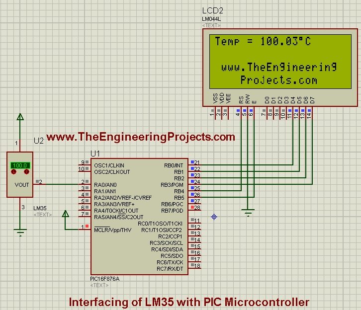
We will use AN0 on RA0 for the sensor and PORTB connections for a four-bit character LCD. The example assumes a nominal 5 V supply that also acts as the ADC reference. Keep this assumption consistent in the circuit and the conversion constant.
Download and Build the Circuit
The original project download contains the historical source and Proteus simulation. Keep it as a reference while building the revised example below. Its arithmetic and formatting may differ from the updated explanation.
Download LM35 Code and SimulationPlace the PIC16F876A, LM35 and character LCD in Proteus. The archived project uses a four-line display; the revised program writes only the first two rows and can therefore also be adapted to a compatible two-line display after checking its connections.
| Part or signal | Connection |
|---|---|
| LM35 positive supply | 5 V for this demonstration |
| LM35 ground | Common ground with the PIC |
| LM35 output | PIC RA0/AN0 |
| LCD RS | RB4 |
| LCD Enable | RB5 |
| LCD D4, D5, D6, D7 | RB0, RB1, RB2, RB3 respectively |
| LCD R/W | Ground for this write-only interface |
| LCD contrast | Adjustable contrast connection appropriate to the display |
Provide the PIC's required supply, reset and oscillator connections. In a physical circuit, place appropriate supply decoupling close to the IC and keep the analog ground path sensible. The LM35 output is measured relative to ground, so a voltage drop in a shared high-current return path becomes a measurement error.
RB3 is also associated with low-voltage programming on this PIC. Disable low-voltage programming in the project configuration when using that pin for the LCD data bus in this arrangement. Set the oscillator configuration to match the actual clock and disable the watchdog for this basic example unless you deliberately add watchdog servicing.
Calculate ADC Resolution and Temperature Scaling
A ten-bit ADC has 1024 possible output codes. With a 5 V reference span, the ideal voltage step is 5000 / 1024 = 4.8828125 mV. Because the LM35 changes by 10 mV per degree, one ADC count represents approximately 4.8828125 / 10 = 0.48828125°C.
Temperature estimate = ADC code × reference voltage / (1024 × 0.010)
Here the reference voltage is expressed in volts. For a code of 51 and a 5 V reference, the estimate is 51 × 5 / 1024 / 0.010 = 24.9023°C. Displaying 24.9°C is reasonable formatting, but the decimal digit does not create a tenth-degree measurement resolution.
The original code used 4.88 as a rounded millivolts-per-count factor. That is close to the ideal value for a 5 V reference, but the variable name did not make its millivolt unit clear. The revised calculation uses a named reference constant and retains the full ratio.
Why 1024 appears instead of 1023
There are 1024 quantization intervals in the ideal ten-bit transfer, while 1023 is the largest output code. Using 1024 describes the nominal step size. Mapping code 1023 exactly to the reference voltage is an alternative endpoint convention, but it should not be confused with a new bit of ADC resolution.
For this thermometer, the uncertainty from the supply reference and sensor can be more significant than the small difference between those conventions. State the convention, keep it consistent and use calibration measurements if you need to correct the complete measurement chain.
mikroC Program for the LM35 and LCD
Create a mikroC PRO for PIC project for the PIC16F876A. For this example, use a 4 MHz project clock and the same clock in Proteus. Enable the ADC and LCD library support required by the calls below.
The mikroC ADC library documentation specifies that ADC_Read initializes the ADC and reads the requested channel. The input direction still needs configuring. This example uses the supply reference supported by that library call; changing to an external reference requires reviewing the driver and device setup.
sbit LCD_RS at RB4_bit;
sbit LCD_EN at RB5_bit;
sbit LCD_D4 at RB0_bit;
sbit LCD_D5 at RB1_bit;
sbit LCD_D6 at RB2_bit;
sbit LCD_D7 at RB3_bit;

sbit LCD_RS_Direction at TRISB4_bit;
sbit LCD_EN_Direction at TRISB5_bit;
sbit LCD_D4_Direction at TRISB0_bit;
sbit LCD_D5_Direction at TRISB1_bit;
sbit LCD_D6_Direction at TRISB2_bit;
sbit LCD_D7_Direction at TRISB3_bit;

const unsigned long referenceMv = 5000UL;
unsigned int adcCode;
unsigned int temperatureTenths;
char valueText[8] = "000.0 C";

void main() {
  TRISA = 0xFF;
  TRISB = 0x00;
  CMCON = 0x07;
  ADCON1 = 0x8E; // Right justified; AN0 analog; VDD/VSS reference.

  Lcd_Init();
  Lcd_Cmd(_LCD_CLEAR);
  Lcd_Cmd(_LCD_CURSOR_OFF);
  Lcd_Out(1, 1, "Temp: ");
  Lcd_Out(2, 1, "LM35 on AN0");

  while (1) {
    adcCode = ADC_Read(0);
    temperatureTenths =
      ((unsigned long)adcCode * referenceMv + 512UL) / 1024UL;

    valueText[0] = '0' + temperatureTenths / 1000;
    valueText[1] = '0' + (temperatureTenths / 100) % 10;
    valueText[2] = '0' + (temperatureTenths / 10) % 10;
    valueText[4] = '0' + temperatureTenths % 10;
    Lcd_Out(1, 7, valueText);
    Delay_ms(250);
  }
}
The numerical value of millivolts equals temperature in tenths of a degree for this sensor: 250 mV corresponds to 250 tenths, or 25.0°C. That relationship lets the example avoid floating-point conversion while keeping one decimal place in the display.
The multiplication is explicitly widened to an unsigned long before it occurs. Multiplying a ten-bit code by 5000 can exceed a sixteen-bit integer's range. Converting the result afterward would be too late if the intermediate multiplication had already overflowed.
Adding 512 before division rounds the positive fixed-point result to the nearest integer rather than always truncating it. The text buffer keeps its decimal point, unit and terminating zero in fixed positions, and every digit is rewritten on each update. A shorter new number cannot leave an old digit behind.
The mikroC LCD library reference documents its four-bit interface and required pin declarations. These declarations must match the schematic exactly. The example uses an ordinary C character for the unit rather than assuming that every display's character ROM assigns the same code to a degree symbol.
Run the Simulation and Interpret the Results
- Compile the program for the selected PIC and clock.
- Assign its HEX to the PIC component in Proteus.
- Check that AN0 receives the LM35 output.
- Set an initial temperature such as 25°C in the sensor model.
- Run the simulation and adjust LCD contrast if needed.
- Change the sensor temperature and wait for the next display update.
- Compare the displayed value with the expected ADC quantization, not only the sensor's ideal setting.

The first archived result demonstrates the basic sensor-to-display path. The revised program may show a slightly different final decimal digit because its conversion and formatting are explicit. A difference of approximately one ADC step should prompt a resolution calculation before you assume the sensor is incorrectly connected.
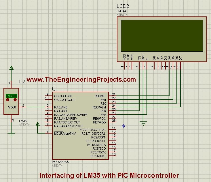
The second archived image shows a higher temperature. At a nominal 100°C, the sensor produces about 1 V, which occupies only one-fifth of a 5 V ADC range. That explains why this simple circuit does not use all ten bits across the sensor's normal positive-temperature range.
Observe the voltage as well as the display
Place a voltmeter or analog probe at the LM35 output. At a selected temperature, compare the voltage with the nominal 10 mV-per-degree relationship. Then inspect the ADC code, either in a debugger or through a temporary diagnostic display.
This divides the system into three questions: is the sensor voltage correct, does the ADC code correspond to that voltage, and does the display correspond to that code? Solving those questions in order is much faster than repeatedly changing the final temperature formula.
Accuracy, Reference Voltage and Calibration
Using VDD as the ADC reference makes the result depend on the actual supply voltage. Suppose the sensor output is 250 mV but the reference is 4.8 V. An ideal code is approximately 250 × 1024 / 4800 = 53.33. Interpreting that code with a 5 V constant produces a temperature that is too high.
Measure the reference in the real circuit and use the appropriate value in the conversion. A regulated supply is not automatically an exact 5.000 V reference. Its tolerance, loading and noise all contribute to the result.
ADC resolution, sensor accuracy and system accuracy are different quantities. Resolution describes the step between codes. Sensor accuracy describes deviation from the specified temperature relationship. System accuracy also includes reference error, ADC characteristics, wiring, thermal placement and any calibration.
A one-point correction can remove an offset near the calibration temperature, but it cannot prove correct scaling over the entire range. A two-point calibration can estimate both offset and gain, provided the reference temperatures and thermal conditions are trustworthy.
Averaging and thermal response
Averaging several samples can reduce random noise when the signal and noise conditions make averaging appropriate. It does not remove a wrong reference constant or a systematic sensor offset. If every sample returns the same ADC code, averaging those identical numbers does not reveal additional information.
Temperature also changes more slowly than the processor can sample. The sensor measures its own local temperature, which may lag behind the air or surface of interest. Place it where that local temperature represents the quantity you actually want, and allow time for thermal settling during calibration.
Limits of This Basic Circuit
The straightforward single-supply connection in this tutorial is intended for positive temperatures. Measuring below zero with an LM35 requires an appropriate circuit that supports the required output behavior, and the PIC input must remain within its permitted voltage range. Follow the manufacturer's application circuits rather than applying a negative voltage directly to AN0.
Long sensor leads introduce additional concerns, including noise pickup and capacitive loading. The LM35 datasheet discusses output loading and stabilization arrangements. Adding a large capacitor directly to an analog output without checking stability is not automatically an improvement.
If you change ADC channels, allow the acquisition conditions required by the device. The input sampling capacitor must settle sufficiently before conversion. Source impedance, channel switching and the chosen driver implementation all affect that process.
Turn a reading into a stable temperature alarm
If you add an alarm output, avoid switching it on and off at exactly the same threshold. Readings near that boundary can move between adjacent ADC codes and repeatedly change the output. Use separate activation and release thresholds, a technique called hysteresis.
For example, an illustrative cooling indicator could activate at 30°C and release below 28°C. With temperature stored in tenths of a degree, those thresholds are 300 and 280. Between them, retain the previous output state. The two-degree gap is an application example, not a universal setting for thermal equipment.
Test the sequence slowly in simulation: increase the temperature through the upper threshold, reduce it to a value between the thresholds and then continue below the lower threshold. The indicator should remain active in the middle region after activation. Repeating the test from a cold startup should show that the middle region also preserves the initially inactive state.
Keep alarm decisions separate from display formatting. Compare the numeric measurement with numeric thresholds; do not parse the text that was created for the LCD. This avoids making control behavior depend on leading spaces, decimal punctuation or a later change in the printed unit.
Also define a policy for implausible readings and a disconnected input. A floating analog pin can produce plausible-looking numbers, so software range checking alone cannot guarantee detection of every wiring fault. Where fault detection matters, design the input circuit and diagnostic method together rather than assuming that an ADC value of zero always means a broken sensor.
For a classroom extension, log the raw ADC code beside the calculated temperature and alarm state. Those three values explain whether a surprising transition came from quantization, arithmetic or the threshold policy.
Troubleshooting and Practical Review
| Symptom | Useful first check |
|---|---|
| Blank LCD | Supply, contrast, initialization and pin declarations |
| Wrong characters | LCD data-line order and clock-dependent timing |
| Constant zero reading | LM35 output connection, AN0 selection and analog configuration |
| Reading near the ADC maximum | Input voltage, ground and reference configuration |
| Temperature consistently scaled incorrectly | Reference voltage and millivolt-versus-volt units |
| Old digits remain on screen | Overwrite a fixed-width display field |
| Hardware differs from simulation | Supply accuracy, sensor orientation, noise and thermal placement |
This project is a useful first analog measurement because the LM35 transfer relationship is easy to calculate. Its main tradeoff is the coarse temperature step obtained when a 10-bit ADC uses a 5 V reference. A lower suitable reference or a different measurement architecture can improve range usage, but requires corresponding hardware and driver changes.
For comparison, see LM35 interfacing with Arduino and using the DS18B20 in Proteus. For display models, the LCD Library V3.0 includes several sizes and interfaces; the parallel 20x4 model is the closest display format to the archived circuit.
Keep the measured supply voltage with your project notes so that another reader can reproduce the conversion assumptions.
Frequently Asked Questions
Why is the result not exactly the selected temperature?
The ADC represents voltage in discrete steps. With a 5 V reference, one count corresponds to about 0.488°C before other error sources are included.
Can I use a PIC16F877A instead?
The same measurement principle applies, but select that device in the compiler and check its package pinout, channel mapping and configuration. Do not move wires by pin number without checking their functions.
Does one decimal place mean 0.1°C accuracy?
No. It is a display format. Accuracy depends on the entire measurement chain and cannot be inferred from the number of digits printed.
Why use unsigned long in the formula?
The intermediate product can exceed sixteen bits. Widening the multiplication before it happens prevents an overflow that would corrupt the temperature calculation.
Can I connect an external reference without changing the program?
No. Check the PIC reference settings, valid reference range and the limitations of the ADC library call, then update both the driver configuration and conversion constant.


Comments
2