


Interfacing of Keypad with PIC Microcontroller


Interfacing of Keypad with PIC Microcontroller
- First of all, you can download the Simulation for this project along with programming code by clicking the below button:
- Now, let's design it step by step.
- I have used LCD Library for Proteus so download it first and then run this simulation.
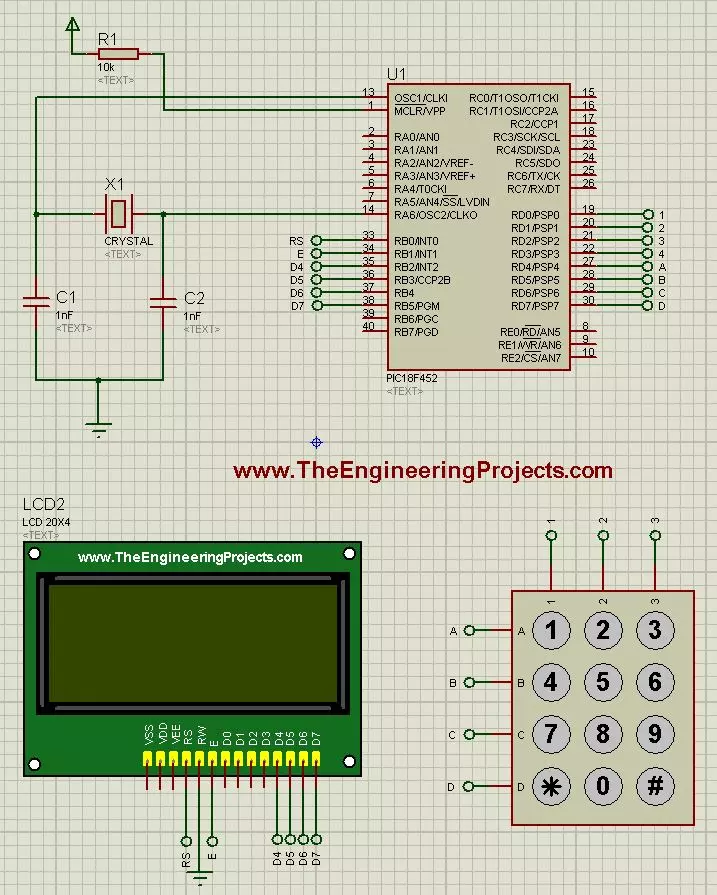
- First of all, design a simple simulation in Proteus software as shown in below figure:
- Now paste the below programming code in MikroC Pro For PIC.
- In this Programming code, the key pressed on keypad will be displayed on the LCD.
- So, when you press any button on the keypad, it will appear on the LCD.
- Here's the code which you need to use in MikroC Pro For PIC:
unsigned short kp, cnt, oldstate = 0;
char txt[6];

char  keypadPort at PORTD;

sbit LCD_RS at RB0_bit;
sbit LCD_EN at RB1_bit;
sbit LCD_D4 at RB2_bit;
sbit LCD_D5 at RB3_bit;
sbit LCD_D6 at RB4_bit;
sbit LCD_D7 at RB5_bit;

sbit LCD_RS_Direction at TRISB0_bit;
sbit LCD_EN_Direction at TRISB1_bit;
sbit LCD_D4_Direction at TRISB2_bit;
sbit LCD_D5_Direction at TRISB3_bit;
sbit LCD_D6_Direction at TRISB4_bit;
sbit LCD_D7_Direction at TRISB5_bit;


void main() {
  cnt = 0;
  Keypad_Init();
  Lcd_Init();
  Lcd_Cmd(_LCD_CLEAR);
  Lcd_Cmd(_LCD_CURSOR_OFF);
  Lcd_Out(3, 2, "The Engineering");
  Lcd_Out(4, 5, "Projects");
   Lcd_Out(1, 1, "Key Pressed:");

  do {
    kp = 0;
    do
      kp = Keypad_Key_Click();
    while (!kp);

    switch (kp) {
      case 10: kp = 42; break;  // '*'
      case 11: kp = 48; break;  // '0'
      case 12: kp = 35; break;  // '#'
      case  1: kp = 49; break; // 1
      case  2: kp = 50; break; // 2
      case  3: kp = 51; break; // 3
      case  4: kp = 65; break; // A
      case  5: kp = 52; break; // 4
      case  6: kp = 53; break; // 5
      case  7: kp = 54; break; // 6
      case  8: kp = 66; break; // B
      case  9: kp = 55; break; // 7
      case 10: kp = 56; break; // 8
      case 11: kp = 57; break; // 9
      case 12: kp = 67; break; // C
      case 13: kp = 42; break; // *
      case 14: kp = 48; break; // 0
      case 15: kp = 35; break; // #
      case 16: kp = 68; break; // D

    }

    Lcd_Chr(1, 14, kp);
  } while (1);
}
- Now get your hex file and upload it in your Proteus Simulation.
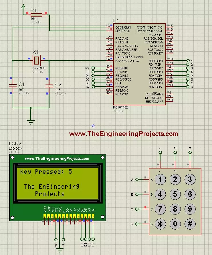
- Run your simulation and if everything goes fine then you will get results as shown in below figure:
- So, in the above figure, I have pressed button 5 on the keypad and it is shown on the LCD.
- Here's the video demonstration which will help you better in understanding this project:
×
![]()


