


Electronic Door Locks using PIC Microcontroller


Today, I am going to share a similar project in which I have simulated an Electronic Door lock using PIC Microcontroller. I have used PIC18F452 Microcontroller and the compiler I have used for designing the code in MikroC Pro For PIC and the simulation is designed in Proteus ISIS. The code and the Proteus simulation are given for download below. You can also design this project using Arduino or any other microcontroller like 8051 Microcontroller. Let's start with this project.
Note:
- You should also have a look at Password Protection using PIC Microcontroller, in which I have designed exactly the same project but using the keypad. The password entered is via keypad instead of Virtual Terminal as in this project.
Electronic Door Locks using PIC Microcontroller
I have divided this Electronic Door Locks Project into few parts, and I have explained them separately. You can download the complete project along with the Proteus simulation by clicking the below button. But as I always suggest don't just download it, also design it on your own so that you learn more from it:
Electronic Door Locks using PIC MicrocontrollerProject Overview of Smart Door Lock
- In this smart door lock project, I have used a solenoid along with a relay.
- We all know that in order to lock a door we have to use either a DC Motor or some solenoid, which should be connected with the manual lock of the door.
- Now, all we need to do is to move that motor according to our needs automatically. Like if I move the motor in one direction, the door goes locked and if I move it in opposite direction then it got unlocked.
- So, in my simulation, I have used a solenoid valve for locking purposes and I have represented it using Inductors in my simulation.
- Moreover, I have used Serial Terminal as a communication medium, means we are gonna input for password etc in the serial monitor.
- I have also used EEPROM in this project to save the current password.
- There's an option in this project to change the password, so if the user changed the current password then the new password will be saved in EEPROM.
- So, even if the device restarts, the newly changed password will remain active as it's saved in EEPROM.
- If the user entered the wrong password then the system will for the password again.
- But if the user entered the wrong password three consecutive times, the system will shut down and will start blinking the RGD lights, which I have used as an indication.
Schematics Diagram of Smart Door Lock
- Let's first design the schematics diagram of the Electronic Smart Door Lock using a PIC Microcontroller.
- I have designed the schematic in Proteus ISIS software as it's the best simulating software.
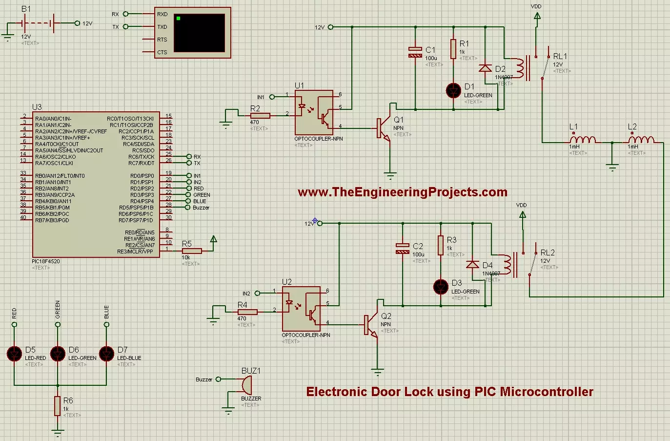
- The schematic diagram is shown in the below figure:
- It's quite clear from the above figure that I have used a PIC Microcontroller as the brain of the system.
- I have a serial terminal, which is used to take inputs from the users.
- I have used two relays and in order to drive those relays, I have used transistors.
- Transistors are converting 5V coming from Microcontroller into 12V which are driving relays.
- Moreover, I have also used optocouplers, which are just used for protection.
- Finally, I have used three LEDs that are acting as RGB and will just indicate the wrong password.
- These two relays are actually actuating the solenoid which will lock or unlock the door.
- There's no active solenoid component available in Proteus that's why I have used a simple inductor.
- Now, let's have a look at the programming code for this project.
Programming Code of Electronic Door Lock
- I have designed the programming code for PIC Microcontroller in MkiroC Pro for PIC compiler.
- You should have a look at these Top 3 PIC C Compilers and can select the one you like.
- The PIC Microcontroller used in this Electronic door locks project is PIC18F4520. You can also use other PIC Microcontrollers like PIC16F877a etc.
- You can use any other PIC Microcontroller if you want. You just need to change it in simulation and in code settings.
- Now here's the complete programming code for Electronic Door Locks using PIC Microcontroller:
 char Indata;
 char P1 = '1';
 char P2 = '2';
 char P3 = '3';
 int PassCheck = 0;
 int WrongCheck = 0;
 int CPassCheck = 0;


void Initialization()
{
      UART1_Init(9600);
      TRISD = 0;
      PortD = 0;
      P1 = EEPROM_Read(0x01);
      P2 = EEPROM_Read(0x02);
      P3 = EEPROM_Read(0x03);
}

void PassChange()
{
            while(1)
            {
                  if (UART1_Data_Ready())
                  {
                        Indata = UART1_Read();

                        if(CPassCheck == 2){
                             CPassCheck = 3;
                             EEPROM_Write(0x03, Indata);
                             P3 = EEPROM_Read(0x03);}
                        if(CPassCheck == 1){
                             CPassCheck = 2;
                             EEPROM_Write(0x02, Indata);
                             P2 = EEPROM_Read(0x02);}
                        if(CPassCheck == 0){
                             CPassCheck = 1;
                             EEPROM_Write(0x01, Indata);
                             P1 = EEPROM_Read(0x01);}
                        UART1_Write_Text("*");
                        if(CPassCheck == 3){break;}
                  }
            }

            UART1_Write(10);
            UART1_Write(13);
            UART1_Write(10);
            UART1_Write(13);
}

void CorrectPass()
{
            UART1_Write(10);
            UART1_Write(13);
            UART1_Write(10);
            UART1_Write(13);
            UART1_Write_Text("Select one of the below Options: ");
            UART1_Write(10);
            UART1_Write(13);
            UART1_Write(10);
            UART1_Write(13);
            UART1_Write_Text("1) Press Y to Lock.");
            UART1_Write(10);
            UART1_Write(13);
            UART1_Write_Text("2) Press N to Unlock.");
            UART1_Write(10);
            UART1_Write(13);
            UART1_Write_Text("3) Press C to Change Password.");
            UART1_Write(10);
            UART1_Write(13);
            UART1_Write(10);
            UART1_Write(13);
            UART1_Write_Text("Waiting for Response: ");

            while(1)
            {
                  if (UART1_Data_Ready())
                  {
                        Indata = UART1_Read();

                        if((Indata == 'Y') || (Indata == 'y')){
UART1_Write_Text("Y");
PortD.F0 = 1;
PortD.F1 = 0;
UART1_Write(10);
UART1_Write(13);
UART1_Write(10);
UART1_Write(13); break;}
                        if((Indata == 'N') || (Indata == 'n')){
UART1_Write_Text("N");
PortD.F0 = 0;
PortD.F1 = 1;
UART1_Write(10);
UART1_Write(13);
UART1_Write(10);
UART1_Write(13); break;}
                        if((Indata == 'C') || (Indata == 'c')){
UART1_Write_Text("C");
UART1_Write(10);
UART1_Write(13);
UART1_Write(10);
UART1_Write(13);
UART1_Write_Text("Enter New Password: ");
PassChange();break;}


                  }
            }
}

void WrongPass()
{
         int x = 0;
         PortD.F5 = 1;
         while(1)
         {

             PortD.F2 = 1;
             Delay_ms(100);
             PortD.F2 = 0;
             PortD.F3 = 1;
             Delay_ms(100);
             PortD.F3 = 0;
             PortD.F4 = 1;
             Delay_ms(100);
             PortD.F4 = 0;
             x = x + 1;
             if(x > 30){break;}
         }
         PortD.F5 = 0;
}


void main() {
      Initialization();

      do
      {
          UART1_Write_Text("Enter Password: ");
          while(1)
          {
                if (UART1_Data_Ready())
                {
                      Indata = UART1_Read();

                      if((Indata == P1) && (PassCheck == 0)){PassCheck = 1;}
                      if((Indata == P2) && (PassCheck == 1)){PassCheck = 2;}
                      if((Indata == P3) && (PassCheck == 2)){PassCheck = 3;}

                      if((Indata == 13) && (PassCheck == 3)){
PassCheck = 0;
WrongCheck = 0;
UART1_Write(10);
UART1_Write(13);
UART1_Write_Text("Correct Password.");
CorrectPass();break;}
                      if((Indata == 13) && (PassCheck != 3)){
PassCheck = 0;
UART1_Write(10);
UART1_Write(13);
UART1_Write_Text("Wrong Password.");
WrongCheck = WrongCheck + 1;
if(WrongCheck == 3){WrongPass();}
UART1_Write(10); UART1_Write(13);
UART1_Write(10); UART1_Write(13);break;}
                      UART1_Write_Text("*");
                }
          }

      } while(1);
}
- I have placed checks on the Enter button like when the user presses Enter button then it will check either password is correct or wrong and then will decide and on or off the respective relays.
- Moreover, the third option is to change the password and you can see right after the change password, I have used EEPROM commands to save the password for later use.
- Let's now start the simulation and test our project.
- Introduction to Relay.
- How to Control Relay in Proteus ISIS.
- Relay Control using 555 Timer in Proteus ISIS.
- Relay Interfacing with Microcontroller using ULN2003A.
- 2 Relay Module Interfacing with Arduino.
Electronic Door Lock Simulation Result
- We have seen all the details about the project and I am quite confident that now you can quite easily design this project on your own.
- So, now let's start the simulation and have a look at the results.
- When you start your simulation then you will have such a screen:
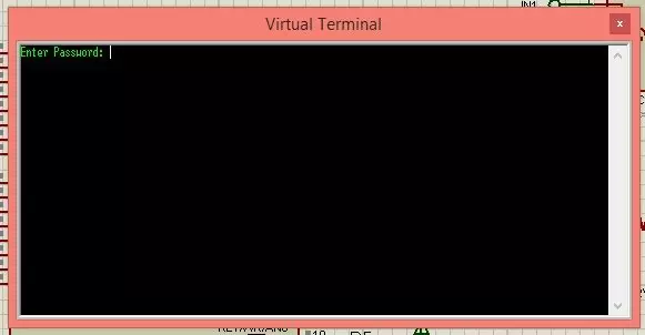
- Now you can see, it's asking for a password in the Virtual Terminal.
- The default password set is "123". So, I am gonna give it 123.
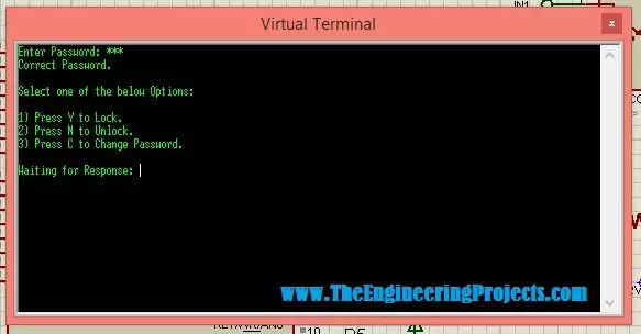
- Now, when I gave it the correct password, it asked for the correct option.
- I have added a total of 3 options to it, which are shown in the above figure.
- So, if the user presses Y then it will lock the door and if he presses N then it will unlock the door and last option is to change the password which is set for C.
- So, that's how this project is working.
- Similarly, if I gave it the wrong password the nit will ask for try again for 3 times and then will set off the RGB lights to warn.
- Complete demonstration and working of this project is given in the below video:
That's all for the electronic smart door lock project using PIC Microcontroller. I hope you have enjoyed it. Will meet you guys in the next tutorial soon. Till then take care and have fun. :)


