Introduction to PIC12F675


In this post, I'll cover each and everything related to this controller including its main features, pinout, pin description, block diagram, and applications. Let's jump right in and nail down everything you need to know.
Introduction to PIC12F675
- PIC12F675 is an 8-pin and 8-bit PIC microcontroller, developed by Microchip with the intention of developing automation and embedded projects.
- Though it comes with a high-performance RISC CPU with interrupt capability, it is not like some other fancy controllers in the PIC community as it lacks a USART module and memory space is quite less as compared to other controllers.
- SPI and I2C communications are not available on the board, but some features like watchdog timer, power-on reset, power on sleep mode and brownout detect (BOD) make this device an ideal choice for some electronic applications.
- Program memory is 1.7KB, enough to store a number of instructions for driving automation, while RAM and EEPROM are 64 and 128 bytes respectively.
- Additionally, the ADC module is added to the device which converts analog signals to digital ones and is mainly used for sensor interfacing and comes with only 4 operating channels.
- Two timers are available onboard where one is an 8-bit timer while the other is a 16-bit timer.
- Only one comparator is incorporated in the module that is mainly used to compare between the two signals where comparator output is externally accessible.
- The 8-bit interface makes it fall under the category of Microchip's Low Pin Count Patent.
- Other valuable functions include ICSP (in-circuit serial programming), programmable code protection, interrupt-on-pin change, power-up timer, Master clear reset and wide industrial and extended temperature range.
PIC12F675 Features
- There are many valuable features added to the device that make it unique in terms of ease of use and innovation.
- The following table shows the full features of PIC12F675:
| PIC12F675 Features | |
|---|---|
| No. of Pins | 8 |
| CPU | RISC 8-Bit PIC |
| Operating Voltage | 2 to 5.5 V |
| Program Memory | 1.7K |
| Program Memory Type | Flash |
| RAM | 64 Bytes |
| EEPROM | 128 Bytes |
| ADC Number of ADC Channels | 10-Bit 4 |
| Comparator | 1 |
| In-circuit serial programming | Yes |
| Oscillator | up to 20 MHz |
| Timer (2) | 16-Bit Timer (1) 8-Bit Timer (1) |
| Oscillator Start-up Timer | Yes |
| Power Up Timer | Yes |
| I/O Pins | 6 |
| Manufacturer | Microchip |
| SPI | No |
| I2C | No |
| Watchdog Timer | Yes |
| Brown out detect (BOD) | Yes |
| Master Clear Reset | Yes |
| Interrupt-on-pin Change | Yes |
| Minimum Operating Temperature | -40 C |
| Maximum Operating Temperature | 125 C |
PIC12F675 Pinout and Description
You have got a hold of the main features of PIC12F675. In this section, we cover the pinout and description of each pin.PIC12F675 Pinout
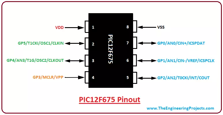
- The following figure shows the pinout of PIC12F675:
- The VDD and VSS are voltage supply and ground pins respectively. Pin 4 is a master clear reset pin used to reset the controller.
- While pin 2 & 3 are connected to a crystal oscillator that creates clock pulses in the controller.
Pin Description
- The following table shows the table of pin description of each pin of PIC12F675, so you can get a hold of the main functions associated with each pin.
| Pin# | Pin Name | Pin Description |
|---|---|---|
| 7 | GP0 AN0 CIN+ ICSPDAT | I/O Bidirectional pin Analog pin channel 0 Comparator In-Circuit Serial Programming |
| 6 | GP1 AN1 CIN- VREF ICSPCLK | I/O Bidirectional pin Analog pin channel 1 Comparator External Voltage Reference In-Circuit Serial Programming Clock |
| 5 | GP2 AN2 T0CKI INT COUT | I/O Bidirectional pin Analog pin channel 2 Timer Interrupt Comparator |
| 4 | GP3 MCLR VPP | I/O Bidirectional pin Master Clear Reset Programming Voltage Input |
| 3 | GP4 AN3 T1G OSC2 CLKOUT | I/O Bidirectional pin Analog pin channel 3 Timer Oscillator Output Comparator |
| 2 | GP5 T1CKI OSC1 CLKIN | I/O Bidirectional pin Timer Oscillator Input RC oscillator connection |
| 1 | VDD | Voltage Supply Pin |
| 8 | VSS | Ground Pin |
PIC12F675 Functions
- This PIC model can perform many functions, if not all, similar to other controllers in the PIC community.
- Following are the main functions of PIC12F675.
Timer
- PIC12F675 comes with two timers where one is 16-bit and the other is an 8-bit timer.
- Both can be used as a timer as well as a counter.
- The timer mode is used to create the delay in any running function that increments the instruction cycle while the counter mode counts the number of intervals in any function and is used to increment the rising and falling edge of the pin.
- Oscillator Start-up Timers
- Power Up Timer
The oscillator start-up timer is a very valuable feature that keeps the module in the reset mode until the crystal oscillator becomes stable. Similarly, a power-up timer is added that generates a delay of 72ms when you power on the device, which gives a proper time to the power supply to stabilize and provide power signals in a continuous manner.
Brown Out Detect (BOD)
- The BOD, also known as BOR (Brown Out Reset), is a very useful function that resets the module once the Vdd (voltage supply) drops below a brownout threshold voltage.
- Sometimes it is very difficult to manually reset the controller if there comes a malfunctioning in the controller, this is where BOD comes into play.
- In this mode, multiple voltage ranges are provided to protect the module once the power drops at the voltage supply line.
It is important to note, the Power Up Timer should be enabled, in order to generate the delay in returning the device from a BOD function. BOD comes with four operating modes that can be programmed by setting or clearing BOREN bits.
- BOD always on
- BOD is controlled by software
- BOD is off when in Sleep mode
- BOD is always off
In-Circuit Serial Programming
Some devices can only be programmed before their installation in the project. This PIC model is an exception that comes with In-circuit serial programming (ICSP), also known as In-system programming (ISP), that helps in programming the module after its installation in the particular project. If you program the module before installation, you need to check and test the program every time its installation in the project.
In-Circuit Serial Programming gives you the flexibility to check the compiled program in the project so you can easily make the required changes and makes it compatible with the running application.
Master Clear Reset (MCLR)
- The MCLR, which is pin 4 in this module, calls the external reset for the chip.
- The reset is configured by keeping this pin LOW that is not dependent on the internal resets.
- The noise filters are present in the MCLR executing process and are very useful to remove and detect small pulses.
Watchdog Timer
- PIC12F675 comes with a built-in watchdog timer that takes the controller in a reset position if the program hangs up during compilation or gets stuck in the infinite loop.
- The watchdog timer is nothing but a countdown timer.
PIC Compiler
- Microchip has created its own standard compiler that is mainly used for the PIC controller called MPLAB C18 Compiler. This compiler is available on the microchip site.
- These Top 3 PIC C Compilers give the flexibility to choose from and pick any compiler as per your requirements, however, MikroC Pro For PIC is a third-party software mainly used as a replacement of Microchip standard compiler.
- The code we write in the compiler generates a hex file which is then uploaded to the microcontroller to execute the number of instructions.
- Burner and Compiler are two different things where Burner is used to burning the required program in the controller and compiler is used to write the program for the controller. The PICKit3 is a standard burner used for the PIC controller.
- There are other burners available in the market but PICKit3 is mostly used and stays ahead of other burners in terms of efficiency and performance.
PIC12F675 Memory Layout
A memory of the controller is very helpful to store the number of instructions in the form of code. The memory is mainly divided into two types
- 1. Program Memory
- 2. Data Memory
Program Memory
- The program memory is also known as the ROM of the controller that stores the information permanently and contains memory space around 1.7K.
- This memory doesn't depend on the power supply source and comes with the ability to retain information in the absence of a power supply.
- It contains a 13-bit program counter that can address 8k x 14 program space where the interrupt vector lies at 0004h while the reset vector stays at 000h and is loaded by the controller.
- The first memory space 1k x 14 rangings (0000h – 03FFh) is physically implemented.
Data Memory
- The data memory, also known as RAM, stores the information temporarily and more often than not is called volatile memory.
- It is widely dependent on the power supply and can not store information in the absence of the power supply.
- The data memory is categorized into two banks that further contain two types of registers called:
- Special Function Registers
- General Purpose Registers
The first 32 locations of each bank are allocated for special function registers that can handle and control the peripheral functions and are classified as “Core and Peripheral”. While general-purpose registers are implemented as static RAM and lie at 20h-5Fh and are mapped across both banks.
PIC12F675 Block Diagram
- Block diagram gives you an overview of different functions and components of the device i.e. how they are used and connected with each other.
- The following figure shows the block diagram of PIC12F675.

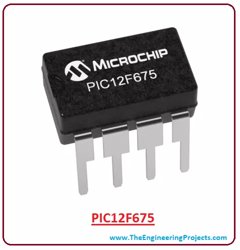
- PIC12F675 is an 8-bit controller that comes in PDIP, SOIC and MLF-S packages, however, PDIP is mainly preferred and used for the development of individual projects.
- The addition of a 10-bit ADC converter makes this device compatible with a number of sensors.
Why Use PIC Microcontroller
Availability of special functions on a single chip is what sets apart PIC controller from other processors. Some real-time applications related to embedded and control systems can only be performed using PIC controllers as they come with high efficiency and decent speed to execute a number of instructions.
These controllers are cheap and remove the need for external components as they can perform a number of operations on a single chip. Power saving modes are added to the device that makes them an ideal choice for applications where power limitation is a major concern.
Maximum code protection is incorporated into the device that saves the device from influencing the code with external parameters, giving full code protection without a minor change in the compiled code.
The watchdog timer is a remarkable feature added in most of the devices that save the module from going into the infinite loop that may hang up the device and puts the device in a total stall.
Needless to say, PIC controllers play a vital role in driving automation in real-time applications using minimum circuitry that covers less space and turns out to be lightweight.
PIC12F675 Projects and Applications
- Mainly used in student projects
- Automation and Embedded Systems
- Motor Controlling and Interfacing with Sensors
- Security Systems
- Industrial Automation
- Medical Equipment
That's all for today. I have tried my best to give you everything related to PIC12F65. However, if you are feeling skeptical or have any questions, you can ask me in the comment section below, I'd love to help you according to the best of my expertise. You are most welcome to keep us updated with your feedback and suggestions so we always come with the relevant content as per your needs and demands. Thanks for reading the article.