Introduction to PIC16F877a


If you are new to PIC Microcontroller then read this complete post carefully and ask your queries in the comments. You should also have a look at this video in which I have given an Introduction to PIC16F877a:
- You can download PIC16F877a Datasheet by Clicking below button:
Introduction to PIC16F877a
- PIC16F877a is a 40-pin PIC Microcontroller, designed using RISC architecture, manufactured by Microchip and is used in Embedded Projects.
- It has five Ports on it, starting from Port A to Port E.
- It has three Timers in it, two of which are 8-bit Timers while 1 is of 16 Bit.
- It supports many communication protocols like:
- Serial Protocol.
- Parallel Protocol.
- I2C Protocol.
- It supports both hardware pin interrupts and timer interrupts.
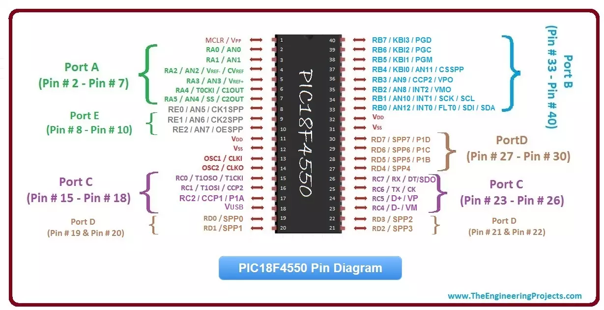
- Here's the PIC16F877a Pin Diagram, I have mentioned the names of all the Pins and have also given different colors to different Ports.

- The above image gives you the overall idea of PIC16F877a Pins and Ports.
- You should also have a look at Introduction to Atmega328, it's another microcontroller, you should compare them.
- You can see in the above image that pins of PIC Microcontroller have more than one name, its because each pin of PIC can perform multiple tasks.
- For example, check Pin # 25, it can be used as a digital Port C Pin # 6 (RC6) and can also be used as a Transmitter (TX) for serial communication.
- So, you have to specify in the programming, how you want to use these pins.
- In the next section, I am going to explain all of these Pin features one by one.
- So, first of all, we are going to have a look at the Basic circuit of PIC16F877a:
PIC16F877a Basic Circuit
- Each Microcontroller has a basic circuit and if you won't design the basic circuit, it won't work.
- It's just like providing power to your PIC Microcontroller and it works on +5V level.
- If you want to turn ON the fan then what will you do? You will simply provide it power and that's what we are going to do with a PIC.
- But in this case, along with power, we also need to provide the frequency at which it will operate.
- So, now we know that we need to design the basic circuit and this basic circuit contains power as well as the frequency at which it will operate.
- In order to provide frequency to PIC Microcontroller, we use a crystal oscillator and for PIC16F877a, you can use a crystal oscillator of frequency range from 4MHz to 40MHz.
- So, here's the PIC16F877a Basic Circuit which you need to design:

- I have tried my best to make this PIC16F877a basic circuit as simple as possible.
- The above circuit may seem a bit complex but it is really not, let me explain it pin by pin:
- Pin # 1: This Pin is called MCLR (Master Clear) and we need to provide 5V to this pin through a 10k-ohm resistance.
- Pin # 11 & Pin # 32: These Pins are labeled as Vdd so we also need to provide it +5V and you can see these lines are in red color in above figure.
- Pin # 12 & Pin # 31: These Pins are Vss, so we have provided GND (Ground) at this pin and its lines are in black color.
- Pin # 13 & 14: These Pins are named OSC1 (Oscillator 1) and OSC2 (Oscillator 2), now we have to attach our Crystal Oscillator (16MHz) at these pins which I have lined in Orange color. After the Crystal Oscillator, we have 33pF capacitors and then they are grounded.
- We have designed our basic circuit and now our PIC Microcontroller is ready to work but you can also see an LED attached at Pin # 21 and that's because we also need to check whether it's running or not so we can turn this LED ON or OFF.
- You should have a look at LED Blinking Project on PIC Microcontroller, in which I have blinked the LED using PIC Microcontroller.
- Here's the video in which I have designed this PIC16F877a basic circuit:
PIC16F877a Pinout
- So, now I hope that you got the complete understanding of PIC16F877a Basic Circuit, so now if you have noticed that in the basic circuit, we have used all the power pins of PIC Microcontroller, while all the Ports Pins were free.
- So, now as we have powered up our PIC Microcontroller, the next thing we need to do is to design some code and use the PIC Microcontroller Ports. First, let's have a look at these PIC16F877a Ports.
- PIC16F877a has 5 Ports in total which are:
- Port A: It has 6 Pins in total starting from Pin # 2 to Pin # 7. Port A Pins are labeled from RA0 to RA5 where RA0 is the label of the first Pin of Port A.
- Port B: It has 8 Pins in total starting from Pin # 33 to Pin # 40. Port B Pins are labeled from RB0 to RB7 where RB0 is the label of the first Pin of Port B.
- Port C: It has 8 Pins in total. Its pins are not aligned together. The first four Pins of Port C are located at Pin # 15 - Pin # 18, while the last four are located at Pin # 23 - Pin # 26.
- Port D: It has 8 Pins in total. Its pins are also not aligned together. The first four Pins of Port D are located at Pin # 19 - Pin # 22, while the last four are located at Pin # 27 - Pin # 30.
- Port E: It has 3 Pins in total starting from Pin # 8 to Pin # 10. Port E Pins are labeled from RE0 to RE2 where RE0 is the label of the first Pin of Port E.
- All these Ports are labeled in the below figure:
- You can see all these PIC16F877a Ports in the above figure, now let's have a look at how to use them.
- First of all, what you need to decide is whether you want your Port Pins to be Input or Output.
- Confused? :P Let's suppose you have some sensor and you want to get its value, then you have to connect this sensor with PIC Microcontroller, now in this case your PIC Pin will be acting as Input Pin because it will be inputting value from the sensor. The sensor is sending the value and PIC is receiving it.
- But in the case of a DC Motor Control with PIC, you have to send commands from PIC Microcontroller to DC Motor, so your PIC Pin is acting as Output Pin.
- Each Port of PIC Microcontroller is associated with two registers, for examples Port D registers are:
- PortD.
- TRISD.
- Both of these registers are of 8 bit because Port D contains 8 Pins.
- TRISD decides whether the Port is output or input and we can also assign values to each pin separately. If we have assigned 0 then it will be OUTPUT and if we have provided 1 then it will be INPUT.
- For example, if I have assigned TRISD = 0x01, then the first 7 pins of Port D will be Output but the last pin will be input because 0x01 is actually 00000001 in binary.
- PortD register contains the actual value and this value is actually the combination of all 8 pins.
PIC16F877a Compiler
- The official Compiler of the PIC Microcontroller is MPLAB C18 Compiler, which is available online from Microchip Official Site.
- There are also other compilers available and the one I normally use is MikroC Pro For PIC.
- You should have a look at this list of Top 3 PIC C Compilers.
- We write code in PIC Compilers and then compile it. After compilation, a hex file is generated which we upload in PIC Microcontroller using a programmer/burner.
PIC16F877a Serial Port
- PIC16F877a has one serial port in it which is used for data communication.
- In the below figure, I have mentioned the Serial Pins of PIC16F877a.

- AS you can see in the above figure that:
- Pin # 25 is acting as TX as well so if you want to do Serial Communication then it will be used for sending the serial data.
- Pin # 26 is acting as RX as well so if you want to do Serial Communication then it will be used for receiving the serial data.
- You should also have a look at What is Serial Port if you don't know much about Serial Port.
PIC16F877a I2C Communication
- PIC16F877a also has one I2C Port using which we can easily do the I2C Communication.
- These PIC16F877a I2C Communication Pins are shown in the below figure:

- As you can see in the above figure, PIC16F877a I2C Communication Pins are:
- Pin # 18: It is acting as SCL which is an abbreviation of Serial Clock Line.
- Pin # 23: It is acting as SDA which is an abbreviation of Serial Data Line.
- Now you can see we have Serial Port and I2C Port in Port C, so we can use Port C as a simple Port but can also do these two communications with its pins, so its totally on the programmer.
PIC16F877a Interrupts
- I hope you all know about interrupts, if not then you should have a look at Interrupts in PIC Microcontroller.
- PIC16F877a has 8 interrupt sources in it. An interrupt source is some event that generates interrupt, this source could be a timer like interrupts are generated after every 1 sec, or it could also be pin state change event, like if pin state is changed then interrupt will be generated.
- So, PIC16F877a Interrupts can be generated by following 8 ways:
- External Interrupts.
- Timer Interrupts ( Timer0 / Timer1).
- Port B State Change.
- Parallel Slave Port Read/Write.
- A/D Converter.
- Serial Receive / Transmit.
- PWM (CCP1 / CCP2).
- EEPROM Write Operation.
- PIC16F877a Interrupts are associated with below 5 registers:
- INTCON
- PIE1
- PIR1
- PIE2
- PIR2
×
![]()