Hey Fellas! Hope you are doing well. Today, I'll uncover the details on the Introduction to PIC12F683. It is an 8-bit PIC microcontroller that contains eight pins and is mainly used for real-time applications related to automation and embedded system.
If you are a newbie or an expert, you need PIC controllers every now and then for the development of electronic projects. These controllers help you drive automation in your projects with the ability to perform a number of functions on a single chip.
In this tutorial, I'll discuss each and everything related to PIC12F683 so you don't have to grapple your mind surfing the whole internet and find all information in one place. Let's dive in and break down everything you need to know.
Introduction to PIC12F683
PIC12F683 is an 8-bit PIC microcontroller that comes with 8-pin interface. It falls under the category of CMOS controllers and comes with nanoWatt technology.
The architecture is based on Flash but controller lacks some functions like USART, SPI, and I2C module, however, features like In-Circuit Serial Programming, Watchdog timer, and Oscillator start-up timer make this device an ideal choice for some real-time applications.
Memory space is less than other 40-pin controllers in the PIC community but is enough to configure automatic functions in the electronic projects.
Program memory comes with 3.5KB memory space, and RAM and EEPROM memories are 128bytes and 256 bytes respectively.
Though this module lacks some major functions, we can't wipe off its value in terms of converting analog signals to digitals ones. This device comes with 10-bit ADC converter that is a remarkable addition in a tiny device like this and is very helpful for sensor interfacing.
Power-up timer, Master Clear Reset, and Sleep Mode are some useful features that work both ways i.e. taking the device out of the infinite loop by restarting it and saving power where power management is a major concern.
With that being said, if your project requires more functions to be carried out on a single chip with more pins and memory interface, it is preferred to use PIC18F4520.
PIC12F683 Features
Features of any device are very important to get the main idea about the device before installing it in the relevant project.
Following table shows the complete features of PIC12F683.
PIC12F683 Features
No. of Pins
8
CPU
RISC 8-Bit PIC
Operating Voltage
2 to 5.5 V
Program Memory
3.5K
Program Memory Type
Flash
RAM
128 Bytes
EEPROM
256 Bytes
ADC
Number of ADC Channels
10-Bit
4
Comparator
1
In-circuit serial programming
Yes
Oscillator
up to 20 MHz
Timer (3)
16-Bit Timer (1)
8-Bit Timer (2)
Oscillator Start-up Timer
Yes
Power Up Timer
Yes
I/O Pins
6
Manufacturer
Microchip
SPI
No
I2C
No
Watchdog Timer
Yes
Brown out Reset (BOR)
Yes
Master Clear Reset
Yes
Interrupt-on-Pin Change
Yes
Minimum Operating Temperature
-40 C
Maximum Operating Temperature
125 C
PIC12F683 Pinout and Description
You have got a complete overview of the features of this module. In this section, we cover pinout and pin description of the chip.
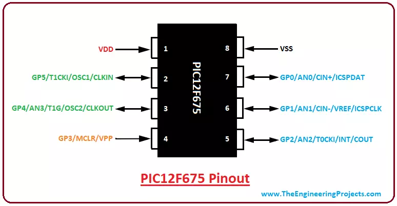
Pinout
The following figure shows the pinout of PIC12F683.
This PIC module comes in three packages named PDIP, DFN and DFN-S and all three packages contain 8-pin on each module.
Pin Description
Following table shows the pin description of each pin that highlights the major functions associated with each pin.
Pin#
Pin Name
Pin Description
7
GP0
AN0
CIN+
ICSPDAT
I/O Bidirectional pin
Analog pin channel 0
Comparator
In-Circuit Serial Programming
6
GP1
AN1
CIN-
VREF
ICSPCLK
I/O Bidirectional pin
Analog pin channel 1
Comparator
External Voltage Reference
In-Circuit Serial Programming Clock
5
GP2
AN2
T0CKI
INT
COUT
I/O Bidirectional pin
Analog pin channel 2
Timer
Interrupt
Comparator
4
GP3
MCLR
VPP
I/O Bidirectional pin
Master Clear Reset
Programming Voltage Input
As I already mentioned, this PIC module is not like some other fancy modules in the market, but some common functions make this device suitable for electronic projects. Let's discuss some major functions of this device.
Timers
There are three timers incorporated in the device where two are 8-bit and one is 16-bit timer. All these timers work both ways i.e. timer as well as the counter. Timer mode is used to create a delay in the execution of relevant functions and increments the instruction cycle. While the counter mode is used to count the number of intervals in the specific functions and increments the rising and falling edge of the pin.
There are some other timers that are separated from mentioned timers and work in the same way to create a delay in the running function of the controller. These timers include
Oscillator Start-up Timer
Power-up Timer
The former is used to create the delay in the oscillator mode until the crystal oscillator becomes stable, while later is used to create the delay of 72ms once the device is powered on. This will give enough time and stabilize the power supply to provide power signals at regular intervals.
Watchdog Timer
The watchdog timer is a remarkable addition in the device that resets the device and puts it in a stable condition if running program hangs up or gets stuck in an infinite loop. When you are playing with the electronic device, it is very difficult to handle and reset the device manually, this is where watchdog timer comes handy and prevents the device from any malfunctioning.
Sleep Mode
Power saving sleep mode is very helpful for saving power that generates a low current power down mode. The sleep mode can be removed using an interrupt, external reset or watchdog timer.
In-Circuit Serial Programming
In-Circuit Serial Programming is another valuable feature added to the device that gives the option to program the controller after its installation in the relevant project, setting you free from separately testing the compiled program every time.
ADC Converter
What this module lacks in terms of USART, SPI, and I2C communications, it covers up for incorporating remarkable ADC converter into the device which makes it an ideal choice for sensor interfacing and for the applications that require analog to digital conversion.
The ADC module is 10-bit and comes with 4-analog channels which are quite less than channels available in other controllers that normally contain 7 or 12 analog channels.
Master Clear Reset (MCLR)
The MCLR pin calls the external reset for the chip that is triggered by keeping this pin LOW. The noise filter is incorporated in the MCLR running process that detects and removes the small pulses. The MCLRE configuration bit is normally used to disable MCLR input.
4. PIC Compiler and Burner
Both, PIC compiler and burner are different things. Former is used to write the required program for the controller while later is used to transfer and burn the written program to the controller.
MPLAB C18 Compiler is a standard compiler for PIC controllers that is introduced by Microchip. This compiler is readily available on the Microchip site.
Third-party software can also be used for compiling the program and you must check this list of Top 3 PIC C Compilers where you can pick any compiler based on your technical requirements, however, MikroC Pro For PIC is a major replacement for standard PIC compiler.
It is important to note that the code we write on the compiler generates the hex which is then moved to the controller for carrying out required operation.
PICKit3 is a standard burner used for PIC controllers. There are other burners available in the market but PICKit3 is mostly used and preferred over other burners in terms of performance and efficiency.
PIC12F683 Memory Layout and Working
Memory, as the word defines, is used to store a number of instructions in the form of code. Memory is mainly divided into two major types
Program Memory Data Memory
The former is used to store the instructions permanently and, more often than not, is known as ROM or Non-Volatile memory. This memory is not dependent on the power supply and comes with an ability to store the information in the absence of power supply.
Program memory comes with a memory space around 3.5K and contains 13-bit program counter that can address 8k x 14 memory space where reset vector lies at 0000h and interrupt vector stays at 0004h.
EEPROM also falls under Program memory and comes with 256 bytes of memory space and is similar to ROM in one way or the other where it stores information permanently but comes with one exception i.e. the EEPROM instructions can be controlled and modified during the controller operation.
The data memory is known as RAM or volatile memory and stores information temporarily i.e. it depends on the power supply and all stored information is gone with the removal of a power supply.
Registers are the data holding places in the controller and can hold storage address, instruction and any kind of data ranging bit sequence or individual characters.
The data memory, implemented as static RAM, is divided into two banks which further contain two types of registers called
General Purpose RegistersSpecial Function Registers
General purpose registers store any modified or random value in the processor, and are accessed by File Select Register. While Special function registers mainly control the peripheral functions and cover first 32 locations of each bank.
General Purpose Registers reserve 20h-7Fh in Bank 0 and A0h-BFh in Bank 1 and are implemented as static RAM while remaining RAM remains unimplemented and returns zero when read.
W Register. The W register falls under GPRs and is accessible by a program. It is important to note that, this register doesn’t take part in any register bank where required values must be written on it and moved to the target register before defining them for available pins.
6. PIC12F683 Block Diagram
Until now, you have got a clear idea about main features, pinout, pin description, and compiler used for this PIC module. In this section, we will discuss the block diagram of this tiny chip.
Following figure shows the block diagram of PIC12F683.
There is no PORT marked on this module, instead, pins are labeled as GP0 to GP5 where VDD and VSS are voltage supply and ground pins respectively. This PIC version falls under the category of Microchip's Low Pin Count Patent.
7. PIC12F683 Projects and Applications
Used in Industrial automation
Embedded and control systems
Sensor interfacing and motor control
Widely used in student projects for driving automation
8. Why Choose PIC Microcontrollers
PIC modules take the whole automation industry by storm with the ability to perform a number of functions on a single tiny chip.
These modules stay ahead of other processors in terms of efficiency and the pace with which they can perform and execute a number of instructions.
Everything is added in the small onboard chip including timers, counters, in-circuit serial programming, ADC converter and the main features required to embed automation in the electronic projects. You name it, they have it.
If you intend to develop any project, the economic price is a major concern. These chips are highly economical and are readily available in the market.
Compact and concise circuitry added on the boards make these devices lightweight which cover less space and prevent you from spending loads of money for buying external components.
That’s all for today. I hope I have given you everything you needed to know about PIC12F683. If you are unsure or have any question, you can approach me in the comment section below. I’ll try my best to help you according to the best of my expertise. Keep us updated with your valuable feedback and suggestions, as they help us provide quality content as per your needs and demands. Thanks for reading the article.