Hello friends! Today we will control a servo motor with the PIC16F877A and observe its movement in Proteus ISIS. We will begin with the three servo connections, understand the command waveform, and then write a small program that selects positions using two pushbuttons. In the previous tutorials, we explored DC motor direction control and stepper motor sequencing . A positional hobby servo is different because the motor, gearbox, position sensor, and controller are already assembled together. Our PIC requests a position rather than switching the motor windings itself. We will keep the original PIC and button arrangement, but use a repeated control pulse with a sensible frame period. Along the way, we will separate what the simulated angle display tells us from what a physical servo must be ...
Hello friends! In the previous tutorial, we controlled the direction of a DC motor in Proteus . Now we will work with a stepper motor, where rotation depends on applying an ordered sequence to the windings. We will begin with the original six-wire simulation, inspect the sequence manually, and then explain how a microcontroller and driver can generate it. The original screenshots use Logic State sources to make individual winding states visible. They are useful for understanding the sequence, but they are not a physical driver circuit. We will preserve the images and add the missing distinction between simulated logic sources, microcontroller outputs, and the winding-current path. By the end, you should understand unipolar and bipolar wiring, wave drive and half stepping, direction reversa ...
Hello friends! In this tutorial, we will design a DC motor control demonstration in Proteus ISIS and then connect its control logic to a PIC16F877A. We will begin by observing how voltage polarity changes the direction of a simulated motor, then explain the driver stage needed between a microcontroller and a physical motor. The original article used Logic State sources and a simplified direct connection to illustrate direction changes. We will preserve those screenshots, but label their purpose clearly. Logic sources and PIC output pins are not substitutes for a motor power driver. The updated practical interface uses an L293D bridge example, with separate logic and motor supplies. We will also correct the relationship between the original schematic and code, add explicit stopping behavior ...
Hello friends! In this tutorial, we will learn how to use Virtual Terminal in Proteus ISIS to inspect serial data and send simple commands to a simulated circuit. It is particularly useful when working with microcontrollers, GSM modules, GPS receivers, and other devices whose behavior can be understood through a serial interface. We will begin with the simplest arrangement: a simulated microcontroller communicating directly with Virtual Terminal. Then we will return to the original article's COMPIM example, which connects a simulation to a real computer serial port. Keeping those two arrangements separate will help you choose the correct components and avoid unnecessary COM-port problems. The aim is to make serial communication visible before building a larger application around it. We wil ...
Hello friends! In this tutorial, we will design a circuit that connects a 16×2 character LCD to a PIC18F452 microcontroller in Proteus ISIS. We will select the components, wire the display, write a small program in mikroC PRO for PIC, load its HEX file into the simulated microcontroller, and display text on both rows. This is a useful first microcontroller simulation because it combines several skills in one manageable circuit: choosing the correct device, matching software pins to schematic wires, setting the clock frequency, and checking the result. If you are new to the workspace, start with our Proteus ISIS and ARES guide , then return here for the practical example. We will preserve the original PORTD connections and two-line website message. The explanation now also covers the LCD co ...
Hello friends! In this tutorial, we will learn how to program a PIC microcontroller with code compiled in mikroC PRO for PIC, using a PICkit 3 programmer. The useful idea is simple: mikroC builds the firmware, and Microchip's programming software loads the resulting HEX file into the selected device. The original project behind this lesson required mikroC, while the available programmer was a USB-connected PICkit 3. Moving from a serial-port programmer to PICkit 3 made the laptop connection easier, but the compiler and programmer still needed a common file format. The HEX file provides that connection without requiring us to compile the project again in another C compiler. We will preserve the original MPLAB IDE screenshot sequence, explain what each step does, and cover the important chec ...
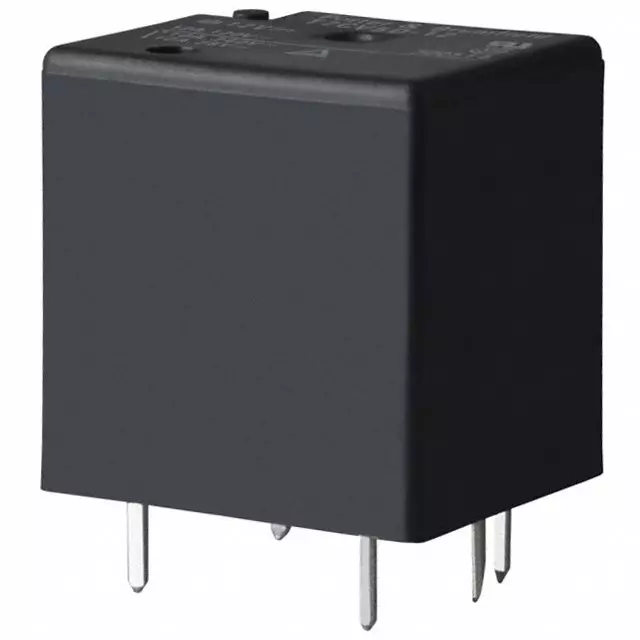
Hello friends, I hope you are doing well. In the previous tutorial, we studied the working principle of a relay . Today, we will connect a 12 V relay to a PIC18F4550 microcontroller through a ULN2003A driver. A relay coil needs more voltage and current than a microcontroller pin should provide. It is also an inductive load, so it produces a voltage transient when switched off. The ULN2003A solves these interface problems by providing seven low-side Darlington drivers and seven internal clamp diodes in one package. The key point is that the ULN2003A does not convert a 5 V logic signal into a 12 V output. The 12 V energy comes from a separate 12 V supply. A logic high merely turns on one internal driver, which connects the low side of the relay coil to ground. We will examine that current pa ...
Hello friends! In this tutorial, we will design an LED blinking project using the PIC16F877A microcontroller. It is a simple project, but it introduces several ideas that appear in almost every embedded system: configuring an I/O port, choosing an oscillator, building a reset circuit, calculating LED resistors, generating a time delay, compiling a program, and loading the resulting HEX file into Proteus. We will connect eight LEDs to PORTB and switch the complete port between logic low and logic high. Once this basic version works, you can change the output patterns and timing to create a running light, binary counter, or status display. The important objective is to understand why every connection and every program statement is present. Figure: The original simulation shows the PORTB LED ...