


Implementing PWM with Raspberry Pi Pico using MicroPython


Hello readers, I hope you all are doing great. In our previous tutorial, we discussed the implementation of LED interfacing and blinking program with Raspberry Pi Pico using MicroPython programming language. So continuing with our previous tutorial, in this tutorial we will learn how to control the LED brightness using PWM (pulse width modulation technique).
As we mentioned above, in our previous tutorial we implemented the LED blinking program with a Raspberry Pi Pico board. Blinking an LED means turning ON and OFF and thus the process involves only two states that are ‘1’ (HIGH) and ‘0’ (LOW). But, sometimes it is required to change the digital output between these two (ON and OFF states) for example changing the LED brightness. PWM or Pulse Width Modulation technique is used to change the brightness of the LED.
Raspberry Pi Pico PWM
Raspberry Pi Pico (RP2040) offers 40 pins which include power supply pins, General Purpose Input Output (GPIOs) pins, ADC, PWM etc. where most of the pins are multifunctional except power supply pins. Almost all the GPIO pins (30 pins) can be used to implement pulse width modulation technology.
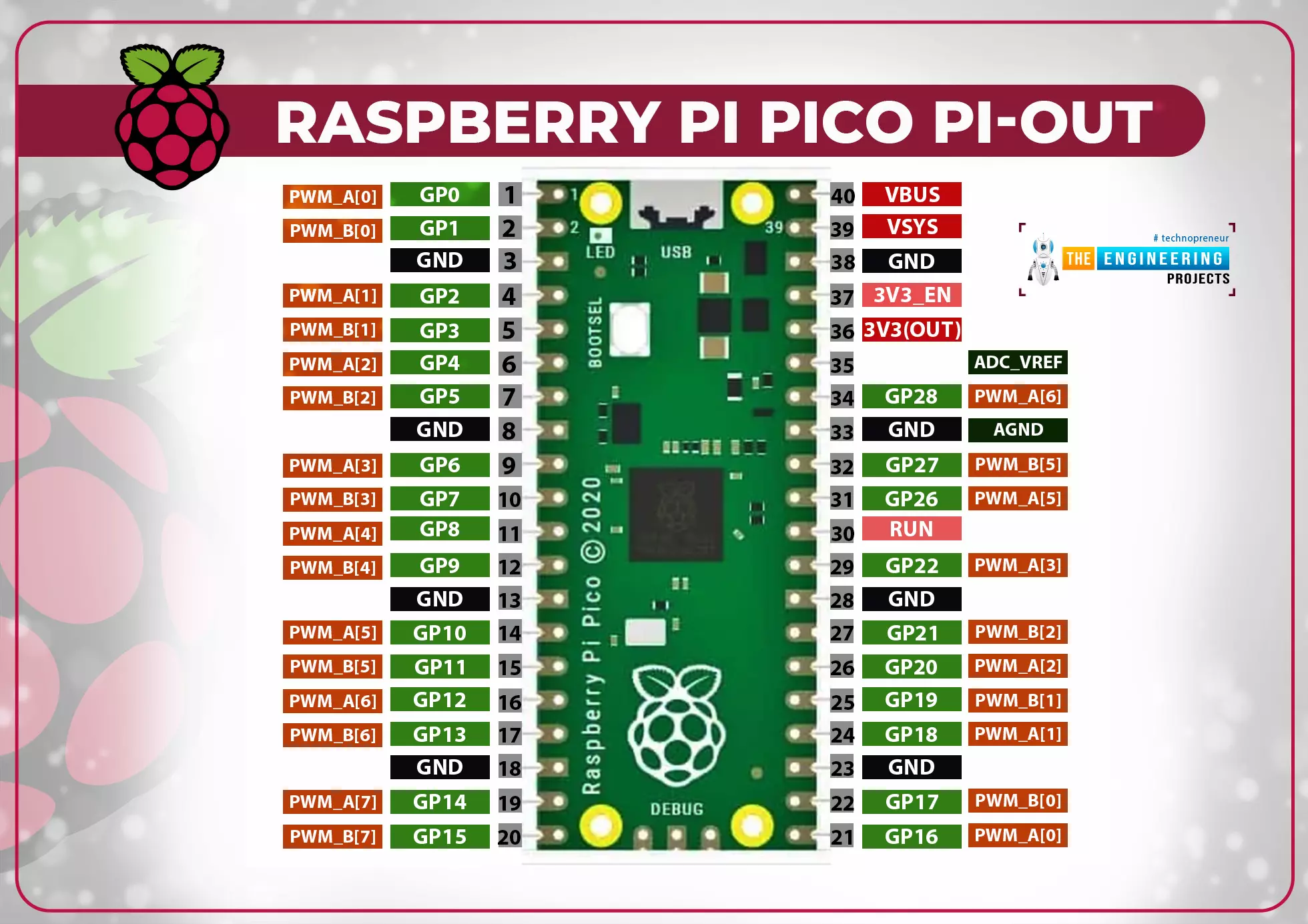
Fig. 1 Raspberry Pi Pico Pi-Out
RP2040 offers 16 PWM channels and each channel is independent of another. Means we can set the duty cycle and frequency for one channels without affecting the others. These PWM channels are represented in the form of slices or groups and each slice contains two PWM outputs channel (A/B). There are total 8 slices and hence 16 channels. The pin B from PWM (A/B) can also be used as an input pin for duty cycle and frequency measurement.
The PWM channel provided in RP2040 are of 16 bit resolution which means maximum PWM resolution is 2^16 or ranges between 0 to 65536.
For more information on Raspberry Pi Pico’s PWM channels you can visit the Raspberry Pi organization’s official website: https://datasheets.raspberrypi.com/rp2040/rp2040-datasheet.pdf
Before programming the Raspberry Pi Pico for PWM implementation let’s first understand the concept of Pulse Width Modulation.
PWM

Fig. 2 Pulse width modulated signal
Pulse Width Modulation (or PWM) is a modulation technique used for controlling the power delivered to a load or external/peripheral devices without causing any power loss by pulsing the direct current (DC) and varying the ON time of the digital pulse. Using a digital input signal, the Pulse Width Modulation technique produces modulated output signals.
The following factors influence the behaviour of a pulse width modulated signal:
- Frequency
- Duty Cycle
- Resolution
Frequency : Technically, frequency means “number of cycles per second”. When we toggle a digital signal (ON and OFF) at a high frequency, the result is an analog signal with a constant voltage level.
The number of cycles per second defined by a signal's frequency is inversely proportional to the time period. PWM frequency is determined by the clock source. The frequency and resolution of PWM are inversely proportional.
Duty Cycle : It is the ratio of ON time (when the signal is high) to the total time taken to complete the cycle.
Duty Cycle =
- The duty cycle is represented in the form of percentage (%) or ratio.
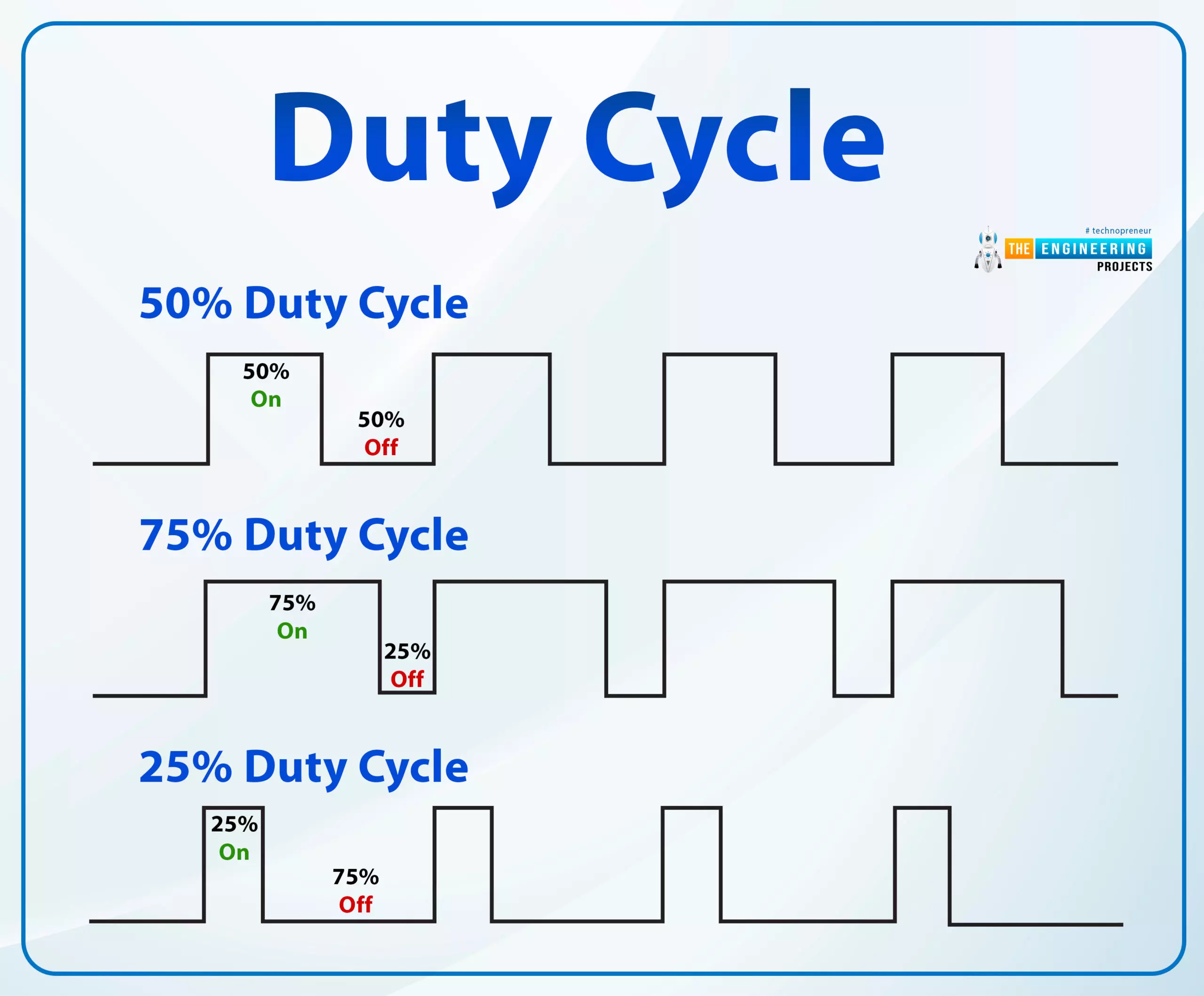
Fig. 3 Duty cycle
Resolution: A PWM signal's resolution refers to the number of steps it can take from zero to full power. The resolution of the PWM signal can be changed. For example, the Raspberry Pi Pico module has a 1- 16 bit resolution, which means we can set up to 65536 steps from zero to full power.
Various applications of Pulse Width Modulation technique are:
- Speed control of DC motor
- Direction or position control of a servo motor
- To control the LED brightness
- Loudness control in buzzers
- Measurements purpose
- Controlling the fan speed
Software and Hardware Components Required
- Raspberry Pi Pico Module
- Latest version of Python
- Latest version on Thonny IDE should be installed on your system
- MicroPython setup installed in Raspberry Pi Pico
- Breadboard
- LED
- Resistor (330 ohm)
- USB cable
We have already published tutorials on how to download and install the above-mentioned software components.
Follow the given link for a detailed study of Raspberry Pi Pico: https://www.theengineeringprojects.com/2022/04/getting-started-with-raspberry-pi-pico.html
Programming Raspberry Pi Pico with MicroPython
To program the Raspberry Pi Pico board there are various development environments available (like uPyCraft IDE, Visual Studio Code, Thonny IDE ect.) and multiple programming languages as well.
In this tutorial, we are going to use Thonny IDE to program the Raspberry Pi Pico board.
Installing Thonny IDE for Raspberry Pi Pico Programming:
We have already published a tutorial on installing Thonny IDe for Raspberry Pi Pico Programming. Follow the given link to install the IDE: https://www.theengineeringprojects.com/2022/04/installing-thonny-ide-for-raspberry-pi-pico-programming.html
Steps to write a program for LED brightness conrtol are:
- Open the installed Thonny IDE for all users.
- Connect the Raspberry Pi Pico development board with your system (laptop or desktop).
- To create a new project; go to Files >> New.
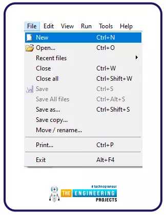
Fig. 4 New Project
- Connect the Raspberry Pi Pico board with laptop/desktop using USB cable.
- Click on the ‘MicoPython(Raspberry Pi Pico)’ option from lower right corner in-order to select the interpreter for raspberry Pi Pico programming using MicroPython programming language. We already selected the one from lower right corner menu from the Thonny IDE window.
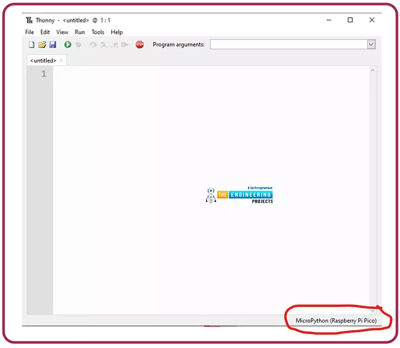
Fig. 5 Select Interpreter
- Select interpreter ‘MicroPython (Raspberry Pi Pico)’ for Raspberry Pi Pico programming.
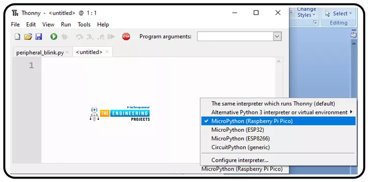
Image: 6 MicroPython for raspberry Pi Pico programming
- You should see this MicroPython Version details in Shell section (to ensure that Thonny is ready to program your Raspberry Pi Pico board) as shown below:
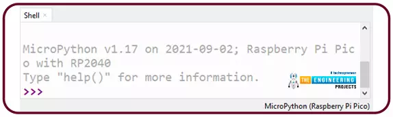
Image: 7 Ready to program
MicroPython program to change the brightness of peripheral LED.
In this example code we will implement the pulse width modulation on the digital output pin (GPIO 14). The brightness of the will vary from minimum to maximum brightness back and forth. The maximum possible resolution is 16 bit that is 2^16 (or 0 – 65535). Let’s write and understand the MicroPython program for PWM implementation:
The first task is importing library files necessary for PWM implementation. We are importing two libraries first one is to access the GPIO pins and another one is to implement pulse width modulation techniques. We also need to import ‘time’ library file to add some delay.

Fig. 8 Import libraries
To define the GPIO pin to be used as a PWM pin a ‘PWM()’ function is used which further contains the ‘Pin()’ function that is passing the PWM GPIO (14) pin number.
The PWM function is further represented using a ‘led’ object. If you are not familiar with the PWM pin details like to which slice and channel the pwm pin belongs, you can get the respective details using print(led) function.

Fig. 9 declare object
The led.freq() command is used to set frequency rate at which the digital pulse will be modulated.

Fig. 10 Frequency of modulation
Inside the while loop we are using two for() loops. First one to change the LED brightness from minimum to maximum resolution (‘0’ to ‘65525’ ).

Fig. 11
Another for loop() is used to set the LED brightness from maximum resolution (65535) to ‘0’ (minimum resolution).
The process will be repeated back and forth due to the ‘while()’ loop.

Fig. 12
Save and test the PWM program
-
- Click on the ‘save’ icon to save the PWM program.
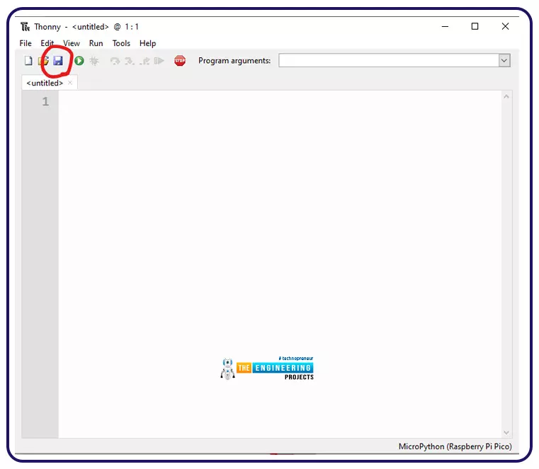
Fig. 13 Save the program
- After clicking on the ‘Save’ icon, an option ‘Where to save to?’ will pop-up. You can select any of the ‘Raspberry Pi Pico’ option.
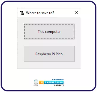
Fig. 14 Save the program
- Run the program once it is successfully saved to change the LED brightness by clicking on the ‘Run’ icon as shown below:
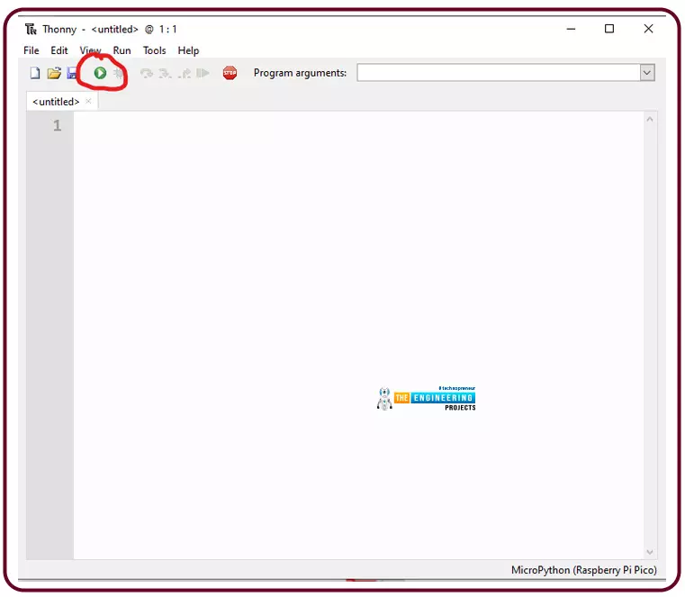
Fig. 15 Run the saved program
Code
from machine import Pin, PWM
import time
led = PWM(Pin(14))
print(led)
led.freq(1000)
while True:
for duty in range(0, 65535):
led.duty_u16(duty)
print(duty)
time.sleep(0.001)
for duty in range(65535, 1):
led.duty_u16(duty)
print(duty)
time.sleep(0.001)
Testing and Results
Let’s interface a peripheral LED with raspberry Pi Pico. As mentioned in the code description the GPIO 14 pin is configured as PWM pin. Connect the LED with raspberry Pi Pico board. The connections of LED with Raspberry Pi Pico board are shown in Table 1.
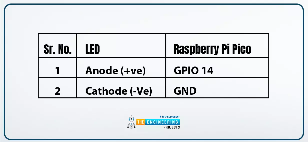
Table 1
Schematic of LED interfacing with raspberry Pi Pico is shown below:
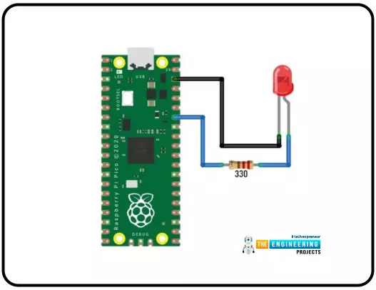
Image: 16 LED Interfacing with Raspberry Pi Pico
- The results of the pulse width modulation implementation on LED are shown in the images attached below.
- In the first image the LED brightness is very low.
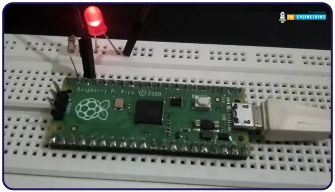
Fig. 17 Brightness level 1
- In the second image the LED brightness is slightly increased than the previous one.
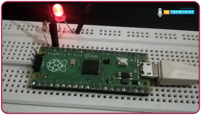
Fig. 18 Brightness level 2
- The third image represents the maximum brightness level.
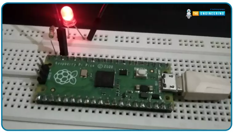
Fig. 19 Brightness level 3
- If you are not familiar with the PMW pin details we can the details of respective pwm pin using print command ‘pritn(“enter the pwm pin here”)’.
- The image attached below represents the PWM pin details like to which slice and channel the PWM pin (GPIO 14) belongs.
- As we can see from the image attached below that PWM slice is ‘7’ and channel is ‘0’.
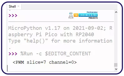
Fig. 20 PWM pin details
- We can also visualize the PWM output on Thonny IDE.
- In Thonny IDE there is a ‘plotter’ feature available for graphical representation.
- To enable the plotter feature, go to View and check the plotter option.
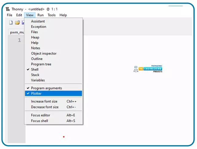
Fig. 21
- Now you should see the plotter section on the right side of Shell
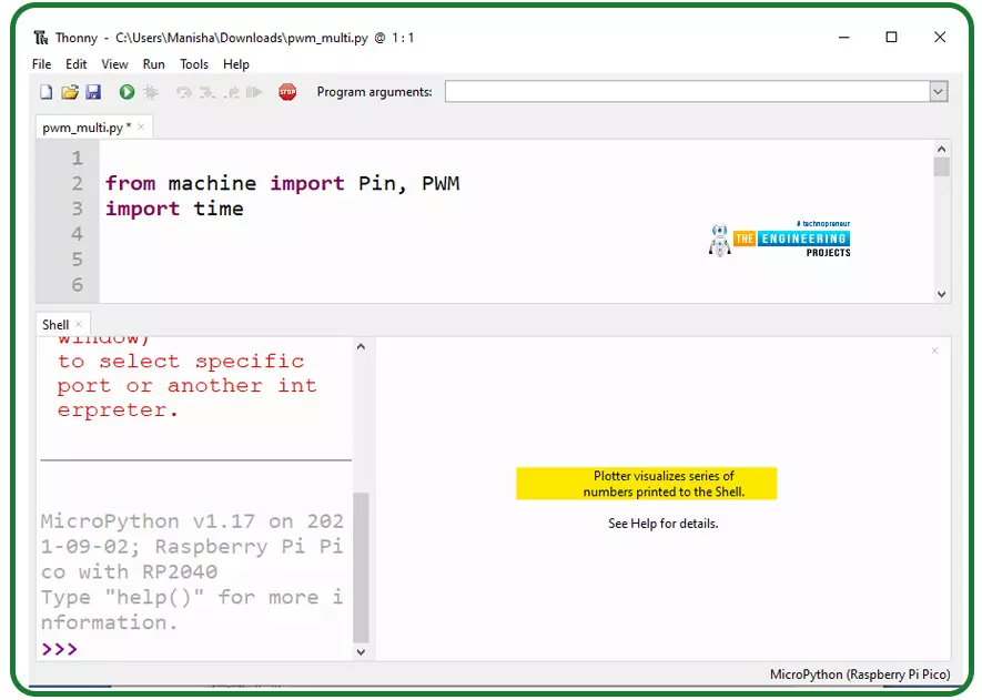
Fig. 22 Plotter
- The duty cycle is printed in both Shell and Plotter using print()
- The image attached below, represents the pulse width modulated output observed from the GPIO 14 PWM pin during rising edge (0 to 65535) or while the LED brightness increasing.
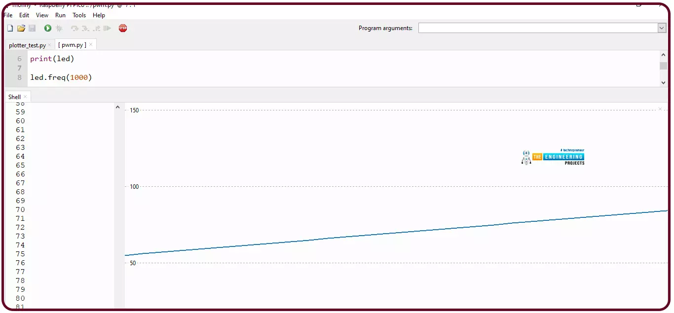
Fig. 23 Rising PWM output 0 to 65535 (brightness increasing)
- Pulse width modulated output during falling edge or decreasing LED brightness (65535 to 0) is shown in the image attached below:
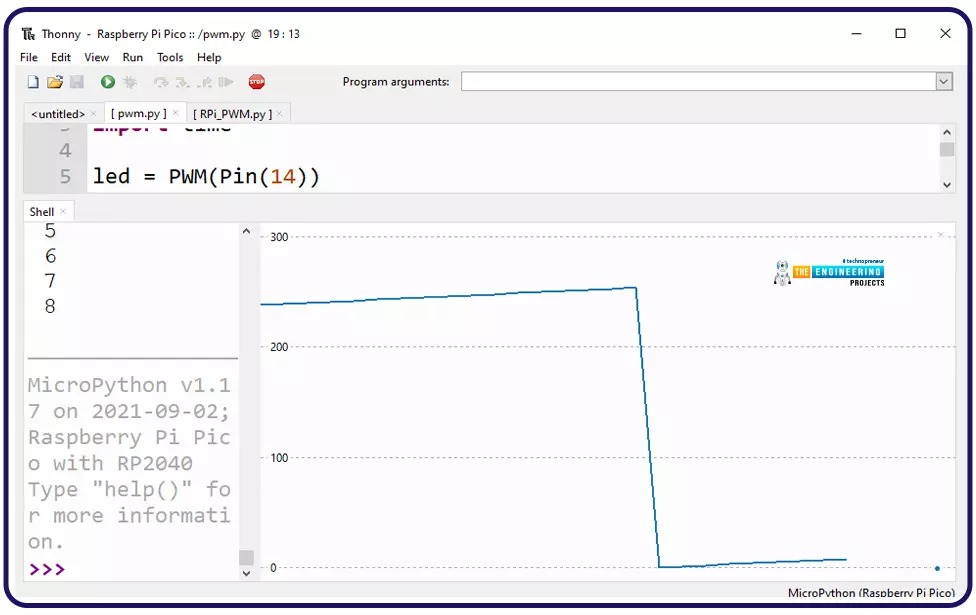
Fig. 24 PWM output maximum to 0
Implementing Pulse Width modulation with multiple LEDs
Now let’s take another example where we will interface multiple LEDs (16) with Raspberry Pi Pico board and then will implement pulse width modulation on those LEDs.
The procedure of interfacing and programming with Thonny IDE using MicroPython will remain similar to the previous example.

Fig. 25 Interfacing Multiple LEDs with Pico
Let’s write the code:
Code
from machine import Pin, PWM
import time
led_1 = PWM(Pin(5)) # declaring led_x object for PWM pins
led_2 = PWM(Pin(6))
led_3 = PWM(Pin(8))
led_4 = PWM(Pin(9))
led_5 = PWM(Pin(10))
led_6 = PWM(Pin(13))
led_7 = PWM(Pin(14))
led_8 = PWM(Pin(15))
led_9 = PWM(Pin(16))
led_10 = PWM(Pin(17))
led_11 = PWM(Pin(18))
led_12 = PWM(Pin(19))
led_13 = PWM(Pin(20))
led_14 = PWM(Pin(21))
led_15 = PWM(Pin(22))
led_16 = PWM(Pin(26))
print(led_1)
def led_freq(x):
led_1.freq(x)
led_2.freq(x)
led_3.freq(x)
led_4.freq(x)
led_5.freq(x)
led_6.freq(x)
led_6.freq(x)
led_7.freq(x)
led_8.freq(x)
led_9.freq(x)
led_10.freq(x)
led_11.freq(x)
led_12.freq(x)
led_13.freq(x)
led_14.freq(x)
led_15.freq(x)
led_16.freq(x)
led_freq(1000) # setting pulse width modulation prequency
while True:
for duty in range(0, 65535): # Increasing LED broghtness
led_1.duty_u16(duty)
led_2.duty_u16(duty)
led_3.duty_u16(duty)
led_4.duty_u16(duty)
led_5.duty_u16(duty)
led_6.duty_u16(duty)
led_7.duty_u16(duty)
led_8.duty_u16(duty)
led_9.duty_u16(duty)
led_10.duty_u16(duty)
led_11.duty_u16(duty)
led_12.duty_u16(duty)
led_13.duty_u16(duty)
led_14.duty_u16(duty)
led_15.duty_u16(duty)
led_16.duty_u16(duty)
print(duty) # Print the duty Cycle
time.sleep(0.001)
for duty in range(65535, 0): # deccresing LED brightness
led_1.duty_u16(duty)
led_2.duty_u16(duty)
led_3.duty_u16(duty)
led_4.duty_u16(duty)
led_5.duty_u16(duty)
led_6.duty_u16(duty)
led_7.duty_u16(duty)
led_8.duty_u16(duty)
led_9.duty_u16(duty)
led_10.duty_u16(duty)
led_11.duty_u16(duty)
led_12.duty_u16(duty)
led_13.duty_u16(duty)
led_14.duty_u16(duty)
led_15.duty_u16(duty)
led_16.duty_u16(duty)
print(duty)
time.sleep(0.001)
Code Description
As we mentioned in the introduction part raspberry Pi Pico has 8 PWM slices and 16 PWM channels. So in this example code we are interfacing 16 LEDs with PWM pins.
Most of the code instructions and commands are similar to the previous example. Here we declare 16 different led objects for 16 different GPIO pins (PWM pins).
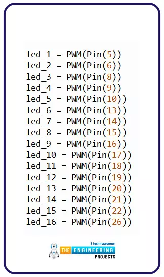
Fig. 26 Declaring ‘led’ object
- Next we created a function ‘led_freq()’ to set the frequency at which pulse width modulation takes place.

Fig.27 PWM frequency
- The programming part of increasing the and decreasing the brightness of LEDs is similar to the previous example.
Result
In the images attached below, we can see the variation in LED brightness.
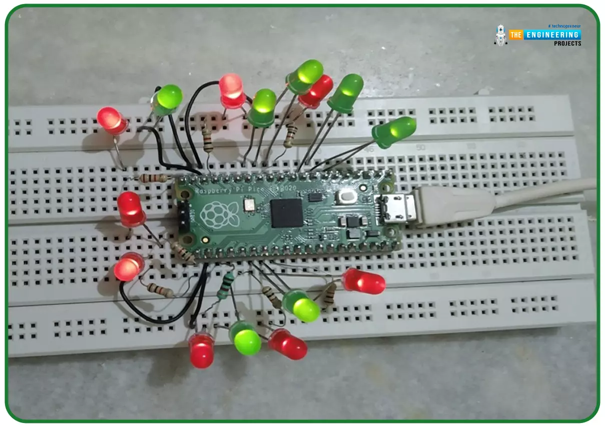
Fig. 28 Minimum Brightness Level
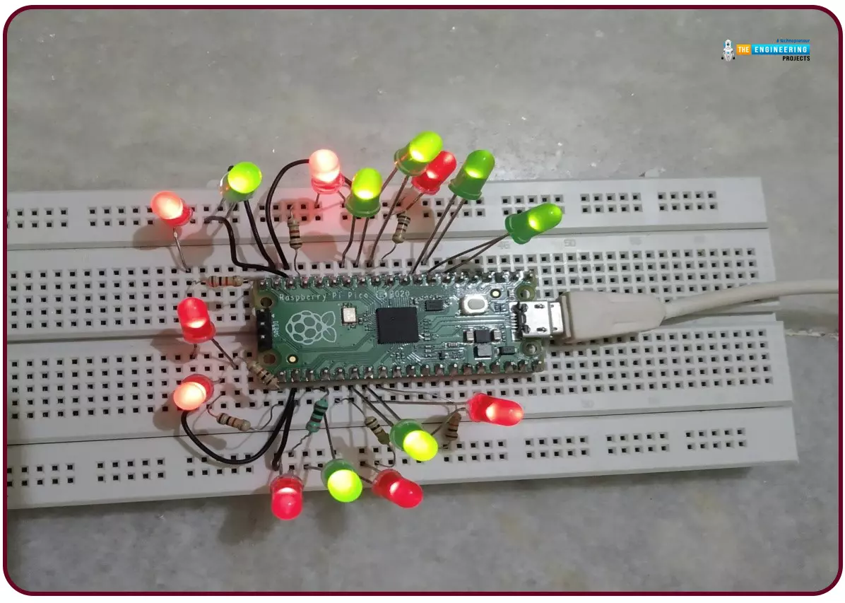
Fig. 29 Intermediate Brightness Level
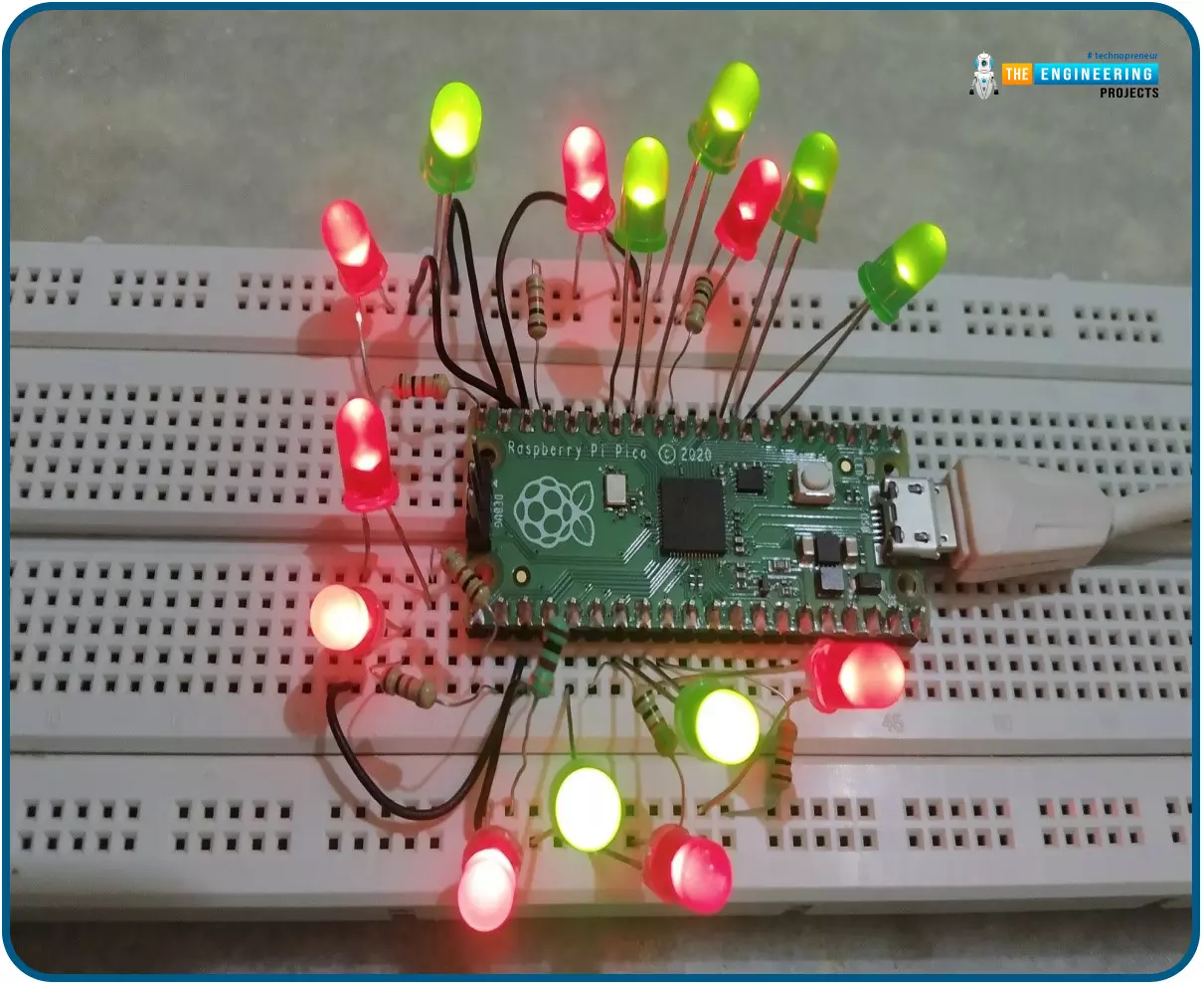
Fig. 30 Maximum Brightness Level
Conclusion
In this tutorial we demonstrated the implementation of pulse width modulation on LEDs with Raspberry Pi Pico module and MicroPython programming language.
Continuing with this tutorial, in our upcoming tutorial we will discuss the interfacing of a servo-motor with raspberry pi Pico and we will also implement PWM on servo motor to control the direction of rotation.
This concludes the tutorial, we hope you find this of some help and also hope to see you soon with a new tutorial on Raspberry Pi Pico programming.


