Hello friends, I hope you are doing well. In today's tutorial, I am going to share our SX1278 LoRa Proteus Library. It adds the popular Ai-Thinker Ra-02 module to Proteus. We can place two of these modules in one design, connect each of them to an Arduino Uno and send messages from one board to the other at 433 MHz. The receiver prints every message with its signal strength and its signal-to-noise ratio, and a row of distance buttons moves the two radios up to 20 km apart.
First, we will look at the SX1278 chip, the Ra-02 board and the basics of LoRa. Then we will install the library files, wire the circuit and run the supplied two-Arduino simulation. The main part of this tutorial is the control panel of the module. We will read every line of it and test how the distance, the spreading factor, the bandwidth and the output power decide whether a packet arrives. Finally, we will understand both Arduino sketches and repeat the calculations of the model by hand.
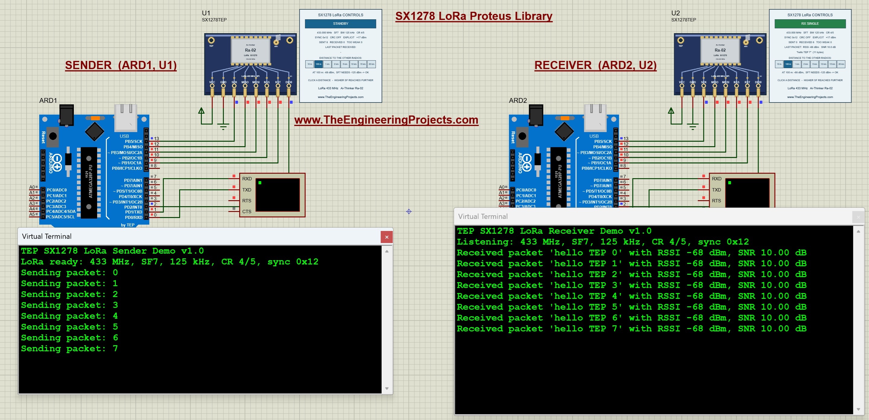
This tutorial uses our V1.1 package, the TEP Arduino UNO V3 and a 16 MHz clock. The package notes record a test of the supplied project in Proteus 8.5 SP0. In the running screenshot below, the sender is on the left and the receiver is on the right. The sender has sent eight messages at the default distance of 100 m. The receiver has printed all eight of them with an RSSI of -68 dBm and an SNR of 10.00 dB.
What Is the SX1278 LoRa Module?
The SX1278 is a long-range radio transceiver chip from Semtech. A transceiver can both transmit and receive, so the same part is used on each side of a wireless link. The chip contains a LoRa modem and covers the lower frequency bands from 137 to 525 MHz. The microcontroller configures it and exchanges data with it through SPI. Semtech describes the chip in the SX1276/77/78/79 datasheet.
Main Features of the SX1278
- It can be tuned from 137 to 525 MHz in steps of 61 Hz.
- Its LoRa modem supports the spreading factors 6 to 12 and bandwidths from 7.8 to 500 kHz.
- Its maximum link budget is 168 dB.
- Its output power goes up to +20 dBm, which is 100 mW.
- Its sensitivity goes down to -148 dBm.
- Its packet engine handles packets of up to 256 bytes with CRC.
- Its supply range is 1.8 to 3.7 V.
The Ai-Thinker Ra-02 Board
The chip is rarely used alone. Most Arduino projects use a small module that carries the chip, its crystal and its antenna matching. The best-known module with the SX1278 is the Ra-02 from Ai-Thinker, and our Proteus component shows this module. The Ra-02 Product Specification V1.1 lists these values:
- The frequency range is 410 to 525 MHz, and the module is normally used at 433 MHz.
- The interface to the microcontroller is SPI.
- The antenna is connected through an IPEX connector.
- The supply range is 2.5 to 3.7 V, with a typical value of 3.3 V.
- The maximum transmit power is 18 dBm, with a tolerance of 1 dB.
- The module measures 17 mm by 16 mm.
How LoRa Reaches a Long Range
A normal radio needs a signal that is clearly stronger than the noise. LoRa works differently. It stretches every symbol into a long sweep over the whole bandwidth, and the receiver adds up the energy of the complete sweep. For this reason, a LoRa receiver can decode a signal that lies below the noise. The range is paid for with time, because a slow setting keeps the packet on the air for much longer. Three settings control this exchange:
- Spreading factor (SF): a number from 6 to 12. Each step doubles the length of a symbol, and the receiver can work with a signal that is 2.5 dB weaker.
- Bandwidth (BW): the width of the signal. Half the bandwidth means 3 dB less noise, but twice the time.
- Coding rate (CR): the amount of error correction. A rate of 4/5 sends five bits for every four data bits.
Important Terms
- dBm: a unit of signal power. A value of 0 dBm is 1 mW, and negative values are weaker signals.
- RSSI: the received signal strength indicator. It tells us how strong the signal was at the receiver.
- SNR: the signal-to-noise ratio in dB. A negative SNR means that the signal is weaker than the noise.
- Noise floor: the power of the noise inside the bandwidth of the receiver.
- Sync word: one byte that separates networks. The receiver accepts only packets with its own sync word.
- Time on air: the time that one packet needs for its transmission.
- Explicit header: a packet format in which a header carries the length, the coding rate and the CRC setting of the packet.
Features of Our Proteus Model
- The component is named SX1278TEP and has eight pins.
- Every LoRa module placed in the same design shares one virtual band, so no wire is needed between the sender and the receiver.
- A control panel beside each module shows its live mode, its settings, its counters and the last packet.
- Eight distance buttons, from 10 m to 20 km, set the distance to the other radios.
- A prediction line tells us whether the present settings can cover the selected distance.
- The model calculates the time on air with the formula of the chip manufacturer.
- The Arduino communicates with the model through real SPI commands and registers, so the unmodified Arduino driver works with it.
Keep one distinction in mind. This is a functional model of the LoRa modem with a simple range calculation. It does not simulate antennas, buildings, reflections or interference. The distance buttons teach us how the LoRa settings and the distance are related, but they do not predict the range of a real installation.
Download the SX1278 LoRa Library for Proteus
First of all, download the V1.1 package using the button below. Extract the complete ZIP into a normal folder before opening the project, and keep the files of the simulation folder together.
Download SX1278 LoRa Proteus Library V1.1 and Arduino Simulation| Folder or file | Contents and purpose |
|---|---|
| Proteus Library Files | TEPSX1278.LIB for the radio module, and the TEP Arduino UNO V3 LIB/IDX files. |
| Proteus Model Files | TEPSX1278.DLL, which provides the simulated behavior of the module. |
| Proteus Simulation | SX1278-ArduinoUnoV3.pdsprj, LoRa_Sender.hex, LoRa_Receiver.hex and a local copy of the DLL. |
| Arduino Code | Both sketches, the arduino-LoRa 0.8.0 driver, the AVR core archive and a firmware rebuild script. |
| Model Source | The chip model, SPI transport, shared radio band and Proteus adapter. |
| Documentation | Model notes, third-party notices and a preview of the board artwork. |
| README.txt and SHA256SUMS.txt | Quick-start instructions and checksums of the packaged files. |
The Proteus library and the Arduino library have different jobs. The LIB file defines the component that we place on the schematic, and the DLL gives it its behavior. The LoRa Arduino library gives our sketch the functions for talking to the radio. Installing the Arduino library alone will not make SX1278TEP appear in Proteus.
What Is New in V1.1
- TEPSX1278.DLL is now the model for our whole LoRa family. The device name selects the chip, so SX1278TEP behaves as an SX1278 and RFM95TEP behaves as an RFM95W.
- All TEP LoRa modules of a design share one radio band.
- Each chip works only inside its own frequency range. For the SX1278, this is 137 to 525 MHz. Outside this range, the panel shows OUT OF BAND.
- The path loss now depends on the frequency. A signal at 868 MHz loses 6 dB more than a signal at 433 MHz.
- The results at 433 MHz are the same as in V1.0.
The library file, the project, both sketches and both HEX files are unchanged. For this reason, the terminal headings still show Demo v1.0. If you installed V1.0 earlier, you only have to replace the DLL in your MODELS folder.
How to Install the SX1278 Library in Proteus
Copy the Library and Model Files
Save your work and close Proteus before copying the files. Then follow these steps:
- Open the extracted Proteus Library Files folder.
- Copy
TEPSX1278.LIBinto the library directory configured for your Proteus installation. - Copy
ArduinoV3TEP.LIBandArduinoV3TEP.IDXfrom the same folder if our TEP Arduino UNO V3 library is not installed already. - Open Proteus Model Files and copy
TEPSX1278.DLLinto your configured ProteusMODELSdirectory. - Restart Proteus, open Pick Devices and search for SX1278TEP. A search for LoRa finds the module as well.
- Place the module on the schematic, or open the supplied project to use the completed circuit.
Points to Remember
- Use the library and model folders that your installation actually searches. Their locations differ between installations.
- The module is supplied as a LIB file without a separate IDX. The included IDX belongs to the Arduino board.
- Keep the extra DLL beside the project in the Proteus Simulation folder.
- Our RFM95W LoRa library uses a DLL with the same name. Keep the newest file in MODELS. The DLL of this V1.1 package serves both modules.
- The two HEX files are programs for the two Arduino boards. The radio module does not need a HEX file.
- Compatibility with Proteus 7 has not been established.
The Arduino board in this project comes from our Arduino Library for Proteus V3.0. Start with the supplied project, so that the boards, wiring and firmware match the demonstration.
SX1278 Pinout and Arduino Uno Wiring
The TEP module has eight pins along its lower edge. From left to right, they are VCC, GND, SCK, MISO, MOSI, NSS, RST and DIO0. Start each wire at the exposed pin endpoint below the board artwork.
| Module pin | Connection | Purpose |
|---|---|---|
| VCC | Positive supply terminal | Powers the digital model. |
| GND | Ground | Provides the shared reference. |
| SCK | Arduino Uno D13 | SPI clock from the Arduino. |
| MISO | Arduino Uno D12 | Data from the module to the Arduino. |
| MOSI | Arduino Uno D11 | Data from the Arduino to the module. |
| NSS | Arduino Uno D10 | Selects the module for an SPI command. It is active low. |
| RST | Arduino Uno D9 | Reset input. It is active low. |
| DIO0 | Arduino Uno D2 | Interrupt output for a received or a sent packet. |
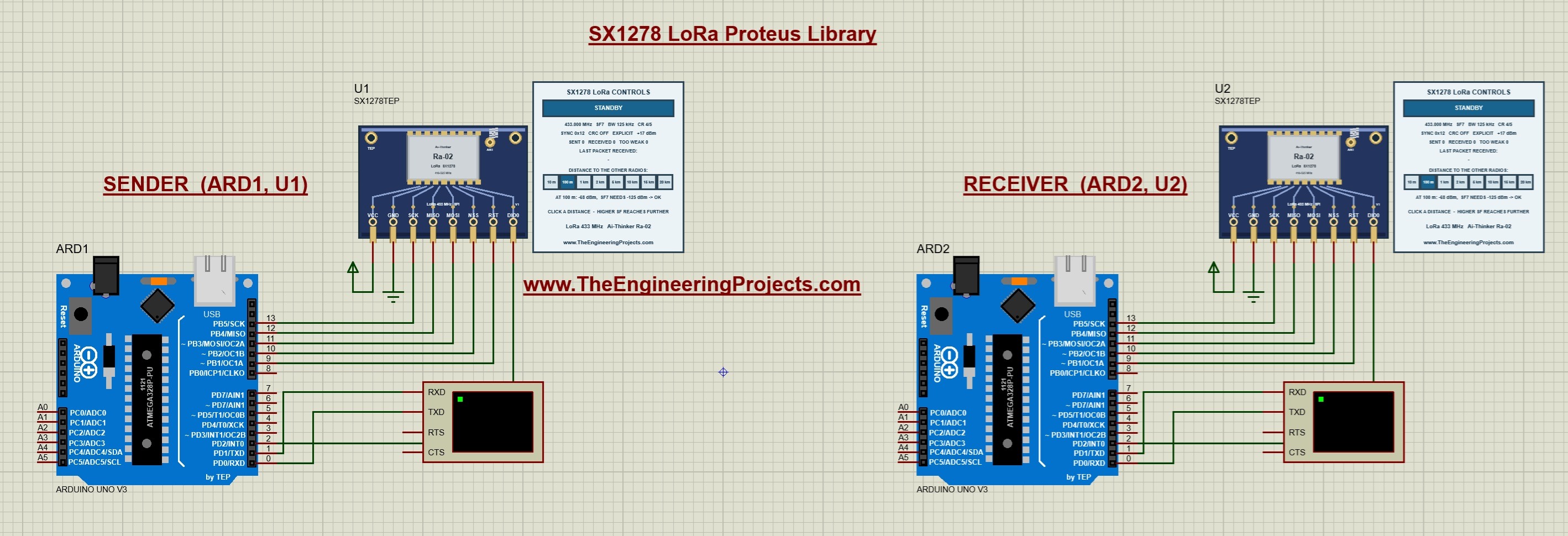
Both boards use the same wiring. The Arduino named ARD1 works with module U1 as the sender, and ARD2 works with U2 as the receiver. Before the simulation starts, both panels show STANDBY, and all counters are zero.
- RST is active low. The driver pulls the pin low for a short time and then high again when it starts the radio.
- DIO0 goes to D2. The supplied sketches read the radio through SPI, so they do not depend on this wire. It is needed for interrupt-based sketches that use the receive callback of the driver.
- There is no wire between U1 and U2. The two modules are connected only through the simulated radio band.
Use Other Arduino Pins
The wiring above follows the default pins of the driver. If your own design needs other pins, call LoRa.setPins(ss, reset, dio0) before LoRa.begin(). Remember two points:
- SCK, MISO and MOSI stay on D13, D12 and D11, because these are the SPI pins of the Arduino Uno.
- For the receive callback, DIO0 must go to an interrupt pin. On the Arduino Uno, these are D2 and D3.
Virtual Terminal Connections
- Connect Arduino D1/TX to RXD on the Virtual Terminal of each board.
- Set both terminals to 9600 baud, eight data bits, no parity and one stop bit.
- The return connection to D0/RX is shown in the circuit, but these sketches do not read typed commands.
Notes for Physical Hardware
- The real Ra-02 is a 3.3 V part with a supply range of 2.5 to 3.7 V. Connecting its supply to 5 V can damage it.
- The model does not check the supply voltage, so a working simulation does not prove that your hardware supply is correct.
- The specification lists a current of 93 mA while the module transmits at 433 MHz. Check that your 3.3 V supply can deliver this current.
- Check the logic levels required by your module before connecting a 5 V Arduino.
- Connect a suitable antenna before you transmit with a real module.
- The specification lists a maximum transmit power of 18 dBm for the Ra-02. The values for +20 dBm in this tutorial are values of the model.
- The rules for 433 MHz differ between countries. Follow the local rules for frequency, power and transmission time.
Run the Two-Arduino Simulation
Start the Simulation
- Open
Proteus Simulation/SX1278-ArduinoUnoV3.pdsprjfrom the extracted package. - Keep both HEX files and
TEPSX1278.DLLin that folder. - Double-click ARD1 and confirm that its Program File is
LoRa_Sender.hex. - Double-click ARD2 and confirm that its Program File is
LoRa_Receiver.hex. - Confirm the 16 MHz clock on both boards and 9600 baud on both terminals.
- Press Run. If the two terminal windows open on top of each other, drag them apart.
Read the Terminal Output
- The sender prints its heading and then LoRa ready: 433 MHz, SF7, 125 kHz, CR 4/5, sync 0x12.
- Every two seconds, the sender prints a line such as
Sending packet: 0. - The receiver prints Listening: 433 MHz, SF7, 125 kHz, CR 4/5, sync 0x12.
- For every message, the receiver prints a line such as
Received packet 'hello TEP 0' with RSSI -68 dBm, SNR 10.00 dB.
In the running screenshot at the top, the sender has printed the messages 0 to 7, and the receiver has printed the same eight messages. Every line shows -68 dBm and 10.00 dB, because the distance stayed at 100 m. The two panels agree with the terminals. The sender's panel shows SENT 8, and the receiver's panel shows RECEIVED 8 and TOO WEAK 0.
Read the Simulation Log
The model also writes short messages into the Simulation Log of Proteus. Each message starts with TEP SX1278 and the name of the module, such as U1.
| Message | Meaning |
|---|---|
| model started, with the chip, the module and the distance | The model has been loaded for this component. |
| powered | The model accepts the VCC and GND connections. |
| NOT powered (check VCC/GND) | VCC is low or GND is high. |
| first packet sent | This radio has completed its first transmission. |
| first packet received, with RSSI and SNR | This radio has received its first packet. |
| packet heard but too weak to decode | A packet with the right settings was below the sensitivity. |
| distance set to, with the new distance | A distance button was clicked. |
| a frequency is outside the SX1278 range 137-525 MHz | The sketch selected a frequency that the chip cannot reach. |
Understand the SX1278 Control Panel
The control panel is the most interesting part of this library. It shows what the radio is doing at every moment, and its distance buttons let us test the link without changing the code. The following picture shows the sender's module U1 and its panel before the first packet has been sent.
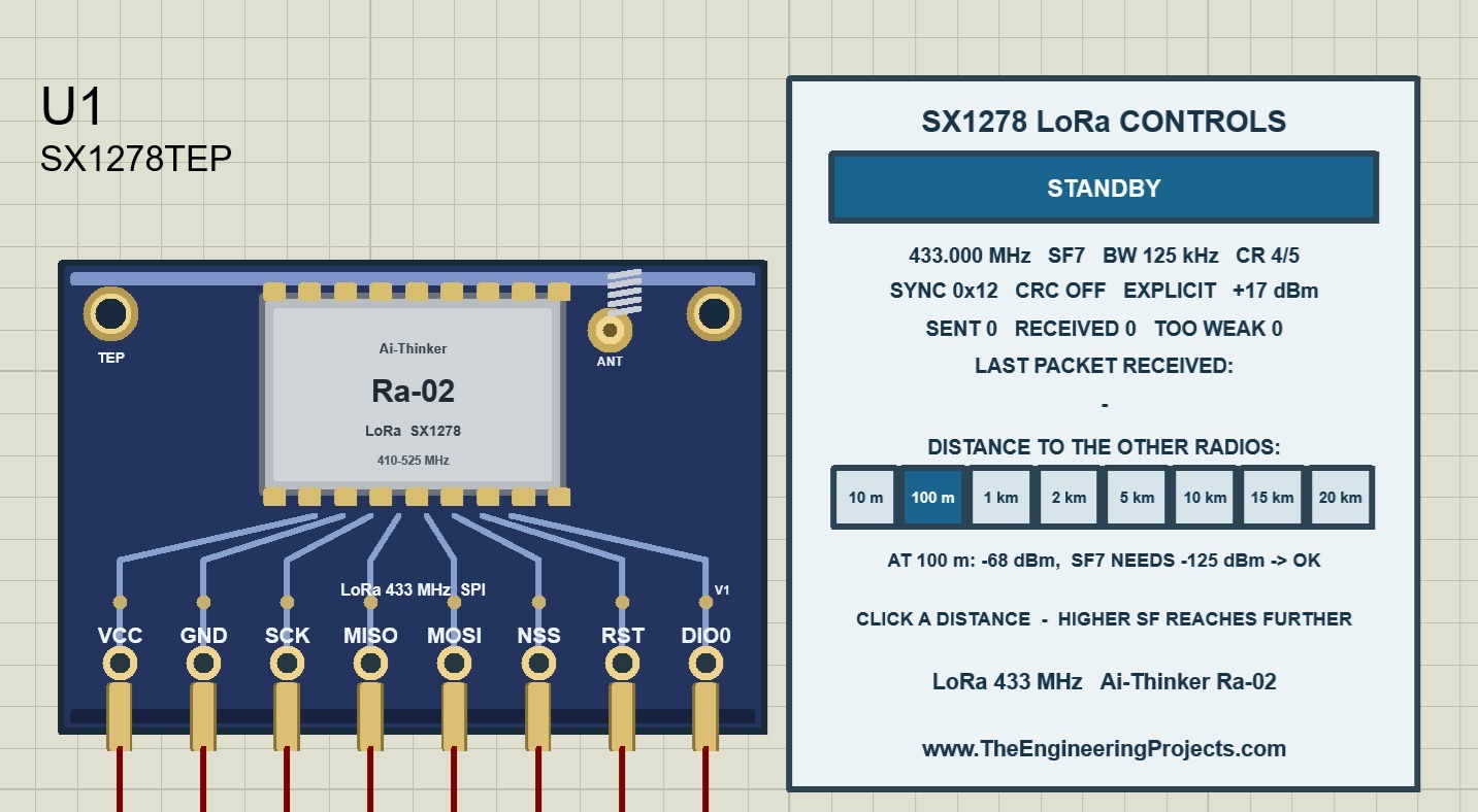
The title of the panel is SX1278 LoRa CONTROLS. Let us go through the panel from top to bottom.
The Mode Banner and Its Colors
| Banner text | Color | Meaning |
|---|---|---|
| SLEEP | Blue | The radio is in its power-saving mode. |
| STANDBY | Blue | The radio is on, but it is neither sending nor listening. |
| FS TX and FS RX | Blue | The frequency synthesizer is running for sending or for receiving. |
| TX - SENDING | Orange | A packet is being sent. |
| RX SINGLE | Green | The radio listens for one packet and stops after a timeout. |
| RX CONTINUOUS | Green | The radio listens until the sketch changes the mode. |
| CAD | Blue | The radio checks whether a LoRa signal is present on the channel. |
| FSK/OOK MODE - NOT MODELLED | Blue | The chip is not in LoRa mode. The model covers the LoRa modem only. |
| NO POWER - CHECK VCC / GND | Red | The module is not powered. |
| SX1278: 868 MHz OUT OF BAND | Red | The selected frequency, here 868 MHz, is outside the range of the chip. Nothing is sent or received. |
The colors make the state of the link visible at a glance. Green means listening, orange means sending, blue means waiting and red means a problem.
Watch One Packet on Both Panels
With the supplied sketches, one message passes through these steps:
- The receiver's banner is green and shows RX SINGLE. The driver function used by the sketch listens in short windows and opens a new window when the old one has ended.
- The sender's banner is blue and shows STANDBY while the sketch waits.
- The sender starts its packet, and its banner changes to TX - SENDING. At the default settings, this lasts for about 41 ms, so the orange color is visible only for a moment.
- The packet ends. The sender returns to STANDBY, and its SENT counter increases by one.
- At the same moment, the RECEIVED counter of the receiver increases, and its LAST PACKET lines show the new message.
- The receiver sketch reads the packet and opens the next receive window.
With a high spreading factor, a packet needs up to one second. You can then see the orange banner clearly.
The Two Settings Lines
The next two lines show the radio settings. They are read from the registers of the chip, so they show what the sketch has really written.
| Value in our example | Meaning | Driver function |
|---|---|---|
| 433.000 MHz | Carrier frequency | LoRa.begin() or LoRa.setFrequency() |
| SF7 | Spreading factor, 6 to 12 | LoRa.setSpreadingFactor() |
| BW 125 kHz | Bandwidth, 7.8 to 500 kHz | LoRa.setSignalBandwidth() |
| CR 4/5 | Coding rate, 4/5 to 4/8 | LoRa.setCodingRate4() |
| SYNC 0x12 | Sync word | LoRa.setSyncWord() |
| CRC OFF | CRC setting, ON or OFF | LoRa.enableCrc() and LoRa.disableCrc() |
| EXPLICIT | Header mode, EXPLICIT or IMPLICIT | The parameter of LoRa.beginPacket() |
| +17 dBm | Output power | LoRa.setTxPower() |
These lines are the quickest way to find a configuration mistake. Put the two panels side by side and compare them:
- The frequency, the spreading factor and the bandwidth must be the same on both panels.
- The sync word and the header mode must be the same as well.
- The coding rate, the CRC setting and the output power may differ.
The Counters
- SENT counts the packets that have left this radio. It increases even when no radio receives the packet.
- RECEIVED counts the packets that this radio has received.
- TOO WEAK counts the packets that matched the settings of this radio but were too weak for its spreading factor.
- CRC ERR appears at the end of the line after the first packet with a CRC error.
The counters of the two panels belong together. As long as the receiver is listening with the same settings, its RECEIVED and TOO WEAK counters normally add up to the SENT counter of the sender. In the running screenshot, this is 8 + 0 = 8. A packet with different settings is not counted by the receiver at all.
| Receiver panel | Meaning |
|---|---|
| RECEIVED increases. | The link works. |
| TOO WEAK increases. | The settings match, but the distance is too large for the spreading factor and the power. |
| CRC ERR appears. | The CRC is switched on, and the signal is at the edge of the sensitivity. |
| No counter changes. | The frequency, the spreading factor, the bandwidth or the sync word is different, or the receiver is not listening. |
The Last Packet Lines
Before the first packet arrives, the panel shows LAST PACKET RECEIVED with a dash below it. You can see this on the sender's panel, because the sender never receives anything. After the first packet, the upper line shows the RSSI and the SNR of the latest packet. The lower line shows the payload in quotation marks, followed by its length. In the running screenshot, the receiver shows -68 dBm, an SNR of 10.0 dB and "hello TEP 7" with 11 bytes. A payload that is not readable text is shown as hexadecimal bytes.
The Distance Buttons and the Prediction Line
Below the heading DISTANCE TO THE OTHER RADIOS, there are eight buttons: 10 m, 100 m, 1 km, 2 km, 5 km, 10 km, 15 km and 20 km. The selected button is dark blue, and the default is 100 m. Click a button while the simulation runs.
The line below the buttons is a prediction. In the picture above, it reads AT 100 m: -68 dBm, SF7 NEEDS -125 dBm -> OK. It has three parts:
- AT 100 m: -68 dBm is the signal strength that a packet from this radio has at the selected distance.
- SF7 NEEDS -125 dBm is the weakest signal that the present spreading factor and bandwidth can decode.
- OK or TOO WEAK is the result of comparing the two values.
The prediction uses the settings of its own panel only. It changes at once when you click another button, and it also changes when the sketch writes a new spreading factor, bandwidth or output power. The last two lines of the panel name the band and the module, which are LoRa 433 MHz and Ai-Thinker Ra-02.
Panel Combinations: Distance, Spreading Factor and Power
Now comes the exciting part. The result of a transmission depends on several settings together, and the panel lets us try them one after the other. The values for 100 m agree with the screenshots of this tutorial, and the package notes record the test with the 10 km button in Proteus. The other values are calculated with the formulas of the model, which we will work through after the code.
Combination 1: The Distances on the Two Panels
Each radio has its own distance buttons. For a packet between two radios, the model uses the larger of the two selected distances.
| Sender panel | Receiver panel | Link distance | RSSI | SNR on the terminal | Result |
|---|---|---|---|---|---|
| 100 m | 100 m | 100 m | -68 dBm | 10.00 dB | Received |
| 2 km | 100 m | 2 km | -107 dBm | 9.75 dB | Received |
| 100 m | 5 km | 5 km | -119 dBm | -2.00 dB | Received |
| 10 m | 10 km | 10 km | -128 dBm | None | Too weak |
| 10 km | 10 m | 10 km | -128 dBm | None | Too weak |
This rule has three consequences:
- To move the radios apart, one click on either panel is enough.
- To bring them together again, both panels must show a short distance.
- The prediction line of one panel can show OK while the packets are too weak, because the other panel has a larger distance. The LAST PACKET line always shows the real value.
Try the Distance Buttons
- Let the simulation run at 100 m and note the RSSI of -68 dBm and the SNR of 10.00 dB.
- Click 1 km on one panel. The RSSI changes to -98 dBm, but the SNR stays at 10.00 dB.
- Click 2 km. The RSSI changes to -107 dBm, and the SNR drops slightly to 9.75 dB.
- Click 5 km. The RSSI changes to -119 dBm, and the SNR becomes negative with -2.00 dB. The signal is now weaker than the noise, and the message still arrives.
- Click 10 km. The receiver stops printing, and its TOO WEAK counter increases with every message of the sender.
- Click 100 m again. The reception returns with the next message.
The fourth step shows the strength of LoRa. A receiver for a simple modulation would have lost the link long before the signal reached the noise.
Combination 2: Distance and Spreading Factor
The hint on the panel says that a higher SF reaches further. This is the most important setting of a LoRa link.
| Distance | RSSI | SF7 | SF8 | SF9 | SF10 | SF11 | SF12 |
|---|---|---|---|---|---|---|---|
| 10 m | -38 dBm | Received | Received | Received | Received | Received | Received |
| 100 m | -68 dBm | Received | Received | Received | Received | Received | Received |
| 1 km | -98 dBm | Received | Received | Received | Received | Received | Received |
| 2 km | -107 dBm | Received | Received | Received | Received | Received | Received |
| 5 km | -119 dBm | Received | Received | Received | Received | Received | Received |
| 10 km | -128 dBm | Too weak | Too weak | Received | Received | Received | Received |
| 15 km | -133 dBm | Too weak | Too weak | Too weak | Too weak | Received | Received |
| 20 km | -137 dBm | Too weak | Too weak | Too weak | Too weak | Too weak | Too weak |
So 10 km needs at least SF9, and 15 km needs at least SF11. At 20 km, even SF12 misses its limit by 0.2 dB. The price of a larger range is time, because every step of the spreading factor almost doubles the time on air.
| Spreading factor | Lowest SNR | Weakest signal | Largest distance at +17 dBm | Time on air |
|---|---|---|---|---|
| SF7 | -7.5 dB | -124.5 dBm | 5 km | 41 ms |
| SF8 | -10 dB | -127.0 dBm | 5 km | 72 ms |
| SF9 | -12.5 dB | -129.5 dBm | 10 km | 144 ms |
| SF10 | -15 dB | -132.0 dBm | 10 km | 248 ms |
| SF11 | -17.5 dB | -134.5 dBm | 15 km | 496 ms |
| SF12 | -20 dB | -137.0 dBm | 15 km | 991 ms |
- To change the spreading factor, add
LoRa.setSpreadingFactor(9);afterLoRa.begin()in both sketches. - The spreading factor must be the same on both sides. A packet with a different spreading factor is not received and not counted.
- After the change, the first settings line shows SF9, and the prediction line shows SF9 NEEDS -130 dBm.
- The sender waits until a packet has been sent. At SF12, every message therefore takes about three seconds instead of two.
Combination 3: Distance and Bandwidth
The bandwidth sets the noise that the receiver collects. A narrow bandwidth has a lower noise floor, so the same signal has a better SNR.
| Bandwidth | Noise floor | Weakest signal | Largest distance | Time on air |
|---|---|---|---|---|
| 31.25 kHz | -123.1 dBm | -130.6 dBm | 10 km | 165 ms |
| 62.5 kHz | -120.0 dBm | -127.5 dBm | 5 km | 82 ms |
| 125 kHz | -117.0 dBm | -124.5 dBm | 5 km | 41 ms |
| 250 kHz | -114.0 dBm | -121.5 dBm | 5 km | 21 ms |
| 500 kHz | -111.0 dBm | -118.5 dBm | 2 km | 10 ms |
- To change the bandwidth, add
LoRa.setSignalBandwidth(31.25E3);afterLoRa.begin()in both sketches. - The bandwidth must be the same on both sides.
- At 500 kHz, a packet needs only 10 ms, but the link ends at 2 km.
- At 31.25 kHz, SF7 reaches 10 km. This is the same distance as SF9 at 125 kHz, and the time on air is similar.
Combination 4: Distance and Output Power
The driver function LoRa.setTxPower() accepts the levels 2 to 20. The output power moves every RSSI value up or down by the same amount.
| Output power | RSSI at 100 m | RSSI at 5 km | Largest distance |
|---|---|---|---|
| +20 dBm | -65 dBm | -116 dBm | 5 km |
| +17 dBm | -68 dBm | -119 dBm | 5 km |
| +14 dBm | -71 dBm | -122 dBm | 5 km |
| +10 dBm | -75 dBm | -126 dBm | 2 km |
| +5 dBm | -80 dBm | -131 dBm | 2 km |
| +2 dBm | -83 dBm | -134 dBm | 2 km |
- To change the power, add
LoRa.setTxPower(20);to the sender afterLoRa.begin(). The panel then shows +20 dBm. - For a packet, only the power of the sending radio matters.
- At SF7, the extra 3 dB of +20 dBm are not enough for 10 km. The signal of -125.2 dBm stays just below the limit of -124.5 dBm.
- The driver uses the PA_BOOST output of the chip. If a sketch selects the other output with
PA_OUTPUT_RFO_PIN, the model reduces the signal by 20 dB, because this output is not connected to the antenna of the Ra-02.
The power and the spreading factor work together. The following table shows the largest distance for both power levels.
| Spreading factor | Largest distance at +17 dBm | Largest distance at +20 dBm |
|---|---|---|
| SF7 | 5 km | 5 km |
| SF8 | 5 km | 10 km |
| SF9 | 10 km | 10 km |
| SF10 | 10 km | 15 km |
| SF11 | 15 km | 20 km |
| SF12 | 15 km | 20 km |
The last button of the panel is therefore reachable only with +20 dBm together with SF11 or SF12. At SF11, the signal is just 0.3 dB above the limit.
Combination 5: SNR and the Edge of the Range
LoRa can decode a signal below the noise, so the SNR is as important as the RSSI.
- The reported SNR is limited to +10 dB. This is why 100 m and 1 km show the same SNR of 10.00 dB, although their RSSI values are different.
- At 2 km, the signal is 9.8 dB above the noise. The terminal shows 9.75 dB, because the chip stores the SNR in steps of 0.25 dB.
- At 5 km, the signal is 2.1 dB below the noise. SF7 needs at least -7.5 dB, so the packet is received.
- At 10 km, the signal is 11.1 dB below the noise. This is too weak for SF7 and for SF8, which needs -10 dB. SF9 needs -12.5 dB, so it receives the same signal.
The CRC adds one more case. When the sender has switched the CRC on with LoRa.enableCrc(), a packet that is less than 1 dB above the limit gets a CRC error in the model. The driver does not pass such a packet to the sketch, so the receiver prints nothing, and CRC ERR appears on its panel. This happens at 20 km with +20 dBm and SF11, where the SNR is -17.2 dB and the limit is -17.5 dB. With SF12, the same packet arrives without an error.
Combination 6: Settings That Must Agree
| Setting | Result of a difference |
|---|---|
| Frequency | Nothing is received, and no counter of the receiver changes. |
| Spreading factor | Nothing is received, and no counter of the receiver changes. |
| Bandwidth | Nothing is received, and no counter of the receiver changes. |
| Sync word | Nothing is received, and no counter of the receiver changes. |
| Header mode | Nothing is received, and no counter of the receiver changes. |
| Coding rate | The packet is received, because the explicit header tells the receiver the coding rate. |
| CRC setting | The packet is received, because the explicit header tells the receiver whether a CRC follows. |
| Output power | The packet is received when the signal is strong enough. |
The sync word is a simple way to separate two networks on the same frequency. The driver's default is 0x12. With LoRa.setSyncWord(0x34); in both sketches, the two radios form their own network. A small frequency difference is accepted. The model receives a packet when the two frequencies differ by no more than a quarter of the bandwidth, which is 31.25 kHz at the default settings.
Combination 7: Other Frequencies and OUT OF BAND
Both sketches call LoRa.begin(433E6). You can use another frequency, as long as both sketches use the same value. The frequency changes the loss of the first metre, so it changes every RSSI value slightly.
| Frequency | Loss of the first metre | RSSI at 100 m | RSSI at 5 km | Largest distance |
|---|---|---|---|---|
| 410 MHz | 24.7 dB | -67.7 dBm | -118.7 dBm | 5 km |
| 433 MHz | 25.2 dB | -68.2 dBm | -119.1 dBm | 5 km |
| 470 MHz | 25.9 dB | -68.9 dBm | -119.9 dBm | 5 km |
| 500 MHz | 26.4 dB | -69.4 dBm | -120.4 dBm | 5 km |
The model accepts the complete range of the chip, which is 137 to 525 MHz. The real Ra-02 is specified for 410 to 525 MHz only. If a sketch calls LoRa.begin(868E6), the following happens in the model:
- The function succeeds, because the chip answers on SPI as before.
- The banner turns red and shows SX1278: 868 MHz OUT OF BAND.
- The Simulation Log explains that 868 MHz is outside the SX1278 range.
- The sender keeps printing its messages, but nothing is radiated and nothing is received.
Arduino Code for the SX1278 Sender
The following is the exact sender sketch included in the download. It uses the bundled arduino-LoRa library, version 0.8.0. Use the supplied copy for your first build, so that your firmware matches the packaged HEX file.
// TEP SX1278 LoRa Sender Demo v1.0
// The Engineering Projects - www.TheEngineeringProjects.com
//
// Sends "hello TEP n" every 2 seconds on 433 MHz (SF7, 125 kHz, CR 4/5, sync 0x12).
// Pair it with LoRa_Receiver on a second Arduino.
//
// Wiring (Arduino UNO, Ra-02 module): VCC -> 3.3V, GND -> GND, SCK -> D13, MISO -> D12,
//   MOSI -> D11, NSS -> D10, RST -> D9, DIO0 -> D2   (the arduino-LoRa default pins)
// Library: LoRa by Sandeep Mistry (Arduino Library Manager: "LoRa")

#include <SPI.h>
#include <LoRa.h>

int counter = 0;

void setup() {
  Serial.begin(9600);
  Serial.println(F("TEP SX1278 LoRa Sender Demo v1.0"));
  if (!LoRa.begin(433E6)) {
    Serial.println(F("LoRa module not responding - check the SPI wiring and power"));
    while (true) {}
  }
  Serial.println(F("LoRa ready: 433 MHz, SF7, 125 kHz, CR 4/5, sync 0x12"));
}

void loop() {
  Serial.print(F("Sending packet: "));
  Serial.println(counter);

  LoRa.beginPacket();
  LoRa.print("hello TEP ");
  LoRa.print(counter);
  LoRa.endPacket();

  counter++;
  delay(2000);
}
Start the Radio
The call LoRa.begin(433E6) sets the frequency to 433 MHz. It does the following work:
- It uses the default pins of the driver, which are D10 for NSS, D9 for RST and D2 for DIO0 on the Arduino Uno.
- It resets the module with the RST pin.
- It reads the version register of the chip. If the value is wrong, the function fails and the sketch prints LoRa module not responding.
- It sets the frequency and an output power of 17 dBm.
- It puts the radio into standby.
The sketch does not set the spreading factor, the bandwidth or the coding rate. The values SF7, 125 kHz, CR 4/5 and the sync word 0x12 are the reset values of the chip, which the driver keeps. The CRC is switched off, and the packets use the explicit header. The text of the LoRa ready line is fixed in the sketch. If you change a setting, the panel shows the new value, but this line does not.
Send a Packet
LoRa.beginPacket()puts the radio into standby and starts a new packet.LoRa.print()writes the text and the counter into the transmit buffer of the chip.LoRa.endPacket()starts the transmission and waits until the chip reports that the packet has been sent.
The message "hello TEP 0" has 11 characters, and the panel of the receiver shows 11 bytes. From message 10 onwards, the counter has two digits, and the packet has 12 bytes. The third step takes as long as the time on air. After it, the sketch increases the counter and waits for two seconds.
Arduino Code for the SX1278 Receiver
The setup part of the receiver is the same as in the sender. Here is the exact sketch from the package:
// TEP SX1278 LoRa Receiver Demo v1.0
// The Engineering Projects - www.TheEngineeringProjects.com
//
// Listens on 433 MHz (SF7, 125 kHz, CR 4/5, sync 0x12) and prints every packet
// with its RSSI and SNR. Pair it with LoRa_Sender on a second Arduino.
//
// Wiring (Arduino UNO, Ra-02 module): VCC -> 3.3V, GND -> GND, SCK -> D13, MISO -> D12,
//   MOSI -> D11, NSS -> D10, RST -> D9, DIO0 -> D2   (the arduino-LoRa default pins)
// Library: LoRa by Sandeep Mistry (Arduino Library Manager: "LoRa")

#include <SPI.h>
#include <LoRa.h>

void setup() {
  Serial.begin(9600);
  Serial.println(F("TEP SX1278 LoRa Receiver Demo v1.0"));
  if (!LoRa.begin(433E6)) {
    Serial.println(F("LoRa module not responding - check the SPI wiring and power"));
    while (true) {}
  }
  Serial.println(F("Listening: 433 MHz, SF7, 125 kHz, CR 4/5, sync 0x12"));
}

void loop() {
  int packetSize = LoRa.parsePacket();
  if (packetSize) {
    Serial.print(F("Received packet '"));
    while (LoRa.available()) {
      Serial.print((char)LoRa.read());
    }
    Serial.print(F("' with RSSI "));
    Serial.print(LoRa.packetRssi());
    Serial.print(F(" dBm, SNR "));
    Serial.print(LoRa.packetSnr());
    Serial.println(F(" dB"));
  }
}
Wait for a Packet
The function LoRa.parsePacket() is called in every loop. It does two things:
- When a packet has arrived without a CRC error, it returns the length of the packet.
- Otherwise it returns zero and makes sure that the radio is listening in single receive mode.
A single receive window ends after 100 symbols, which is about 102 ms at SF7. The next call of the function opens a new window. This is why the banner of the receiver shows RX SINGLE.
Read the Packet and Its Values
LoRa.available()andLoRa.read()return the bytes of the packet one after the other.LoRa.packetRssi()returns the signal strength of the packet in dBm as a whole number.LoRa.packetSnr()returns the SNR of the packet in dB. It is a number with decimals, so the terminal prints 10.00 and 9.75.
Use the Continuous Receive Mode
The driver offers a second way of receiving. The function LoRa.onReceive() registers a callback function, and LoRa.receive() puts the radio into the continuous receive mode. The chip then raises DIO0 for every packet, and the interrupt on D2 calls the callback function. With such a sketch, the banner of the receiver shows RX CONTINUOUS. The package contains the examples of the driver for this mode in the folder Arduino Code/libraries/LoRa/examples.
Calculate the Link Budget
A link budget tells us whether the signal at the receiver is strong enough. The model uses four steps, and we can repeat them with a calculator.
Step 1: Calculate the Path Loss
The model uses the free-space loss for the first metre, and then a loss that grows with 30 dB for every ten-fold increase in distance:
Path loss in dB = 20 × log10(4 × pi × f / c) + 30 × log10(distance in metres)
Here, f is the frequency in Hz and c is the speed of light. At 433 MHz, the first part is 25.18 dB. For 5 km, the second part is 30 × 3.699 = 110.97 dB. The path loss at 5 km is therefore 136.15 dB.
Step 2: Calculate the RSSI
RSSI = output power - path loss
- 100 m: the path loss is 25.18 + 60 = 85.18 dB, so the RSSI is +17 - 85.18 = -68.18 dBm. It is displayed as -68 dBm.
- 5 km: +17 - 136.15 = -119.15 dBm, which is displayed as -119 dBm.
- 10 km: the path loss is 25.18 + 120 = 145.18 dB, so the RSSI is -128.18 dBm.
Step 3: Calculate the Noise Floor
Noise floor in dBm = -174 + 10 × log10(bandwidth in Hz) + 6
The value -174 dBm is the thermal noise in a bandwidth of 1 Hz, and 6 dB is the noise that the model adds for the receiver. For 125 kHz, the middle part is 50.97 dB. The noise floor is -174 + 50.97 + 6 = -117.03 dBm.
Step 4: Calculate the SNR and Compare
SNR = RSSI - noise floor
- 100 m: -68.18 + 117.03 = 48.85 dB. The reported value is limited to 10 dB.
- 5 km: -119.15 + 117.03 = -2.12 dB. SF7 needs -7.5 dB, so the packet is received.
- 10 km: -128.18 + 117.03 = -11.15 dB. This is below -7.5 dB, so the packet is too weak for SF7.
The weakest signal for a spreading factor is the noise floor plus its lowest SNR. For SF7, this is -117.03 - 7.5 = -124.53 dBm, which the panel shows as -125 dBm.
Calculate the Time on Air
The model uses the time-on-air formula of the chip manufacturer. For our example, we need these values: SF7, 125 kHz, coding rate 4/5, a preamble of 8 symbols, the explicit header, no CRC and a payload of 11 bytes.
- The symbol time is 2 to the power of SF, divided by the bandwidth. This is 128 / 125,000 = 1.024 ms.
- The preamble needs 8 + 4.25 = 12.25 symbols.
- For the payload, we calculate 8 × 11 - 4 × 7 + 28 = 88 and divide it by 4 × 7 = 28. The result of 3.14 is rounded up to 4.
- The payload needs 8 + 4 × 5 = 28 symbols. The number 5 comes from the coding rate 4/5.
- The packet has 12.25 + 28 = 40.25 symbols, which take 40.25 × 1.024 = 41.2 ms.
At SF12, the symbol time is 4096 / 125,000 = 32.768 ms. For such long symbols, the driver switches on the low data rate optimization of the chip, which replaces the divisor by 4 × (12 - 2) = 40. The payload then needs 18 symbols, and the packet has 30.25 symbols. They take 30.25 × 32.768 = 991 ms.
Convert the Registers to dBm and dB
- The chip stores the RSSI of a packet as one byte. For frequencies below 525 MHz, the driver calculates RSSI = register value - 164. At 5 km, the register holds 45, and 45 - 164 = -119 dBm.
- The chip stores the SNR in steps of 0.25 dB. The driver calculates SNR = register value × 0.25. At 5 km, the register holds -8, and -8 × 0.25 = -2.00 dB.
This explains a small difference between the two displays. The panel shows the calculated SNR with one decimal, which is -2.1 dB at 5 km. The terminal shows the register value of -2.00 dB.
Calculate the Frequency Setting
The chip uses a 32 MHz crystal. One frequency step is 32 MHz / 524,288 = 61 Hz. For 433 MHz, the driver calculates 433,000,000 × 524,288 / 32,000,000 = 7,094,272. In hexadecimal, this number is 0x6C4000, and the driver writes the bytes 0x6C, 0x40 and 0x00 into three registers.
SX1278 and RFM95W in One Design
We have also published an RFM95W LoRa library for Proteus. Both libraries use the same model file, so the two modules can be placed in one design.
| Property | SX1278TEP | RFM95TEP |
|---|---|---|
| Module | Ai-Thinker Ra-02 | HopeRF RFM95W |
| Chip | SX1278 | SX1276 |
| Frequency range of the model | 137 to 525 MHz | 137 to 1020 MHz |
| Frequency of the example | 433 MHz | 868 MHz |
| Loss of the first metre | 25.2 dB | 31.2 dB |
| RSSI at 100 m and +17 dBm | -68 dBm | -74 dBm |
| Largest distance at SF7 and +17 dBm | 5 km | 2 km |
| RSSI calculation of the driver | Register value - 164 | Register value - 157 |
- The lower frequency is the reason for the larger range. In the model, 433 MHz has 6 dB less path loss than 868 MHz.
- In the simulation, the two modules can exchange packets when both sketches use the same frequency and LoRa settings. The frequency must lie inside both ranges, for example 433 MHz.
- This is an experiment for the simulation. A real RFM95W is built for 868 and 915 MHz, and a real Ra-02 is built for 410 to 525 MHz.
- Both components need the same TEPSX1278.DLL, because only one model file can hold the shared radio band.
Experiments to Try in Proteus
Change one thing at a time and predict the result before you press Run. The results below follow from the model's rules. The supplied project and the 10 km button were tested in Proteus. The package notes list the other cases as tests of the model on a PC, so check them in your own simulation.
| Change | Expected result |
|---|---|
| Click 10 km on either panel. | The receiver prints nothing, and its TOO WEAK counter increases. |
Add LoRa.setSpreadingFactor(9) to both sketches. | The link works at 10 km with -128 dBm and an SNR of -11.25 dB. |
Add LoRa.setSpreadingFactor(9) to one sketch only. | Nothing is received, and no counter of the receiver changes. |
Add LoRa.setTxPower(20) to the sender. | The receiver shows -65 dBm at 100 m. |
Add LoRa.setTxPower(2) to the sender. | The receiver shows -83 dBm at 100 m, and 5 km becomes too weak. |
Add LoRa.setSyncWord(0x34) to the sender only. | Nothing is received, and the panels show different sync words. |
| Change the frequency to 434E6 in one sketch only. | Nothing is received, and the panels show different frequencies. |
Add LoRa.setSpreadingFactor(12) to both sketches. | The sender's banner shows TX - SENDING for about one second for every message. |
| Change the frequency to 868E6 in both sketches. | Both banners turn red and show OUT OF BAND. |
| Connect VCC of the receiver's module to ground. | The banner of this module turns red and shows NO POWER - CHECK VCC / GND. |
After each experiment, compare both panels before reading the code again. A difference in frequency, spreading factor, bandwidth or sync word is visible there.
Compile and Load Your Own Arduino Changes
- Open
Arduino Code/LoRa_Sender/LoRa_Sender.inoor the receiver sketch in Arduino IDE. - Install the LoRa library by Sandeep Mistry. For the same version as the example, copy
Arduino Code/libraries/LoRainto your sketchbook's libraries folder. - Select Arduino Uno as the board.
- Compile the sketch and use the Export Compiled Binary command.
- Select the new application HEX in the Program File property of the correct Arduino.
- Restart the simulation.
Remember that the project has two programs. If you change a radio setting, rebuild both sketches and load each HEX into its own board. The package also contains a rebuild script and the AVR core source archive.
Common Problems and Their Solutions
| Problem | What to check |
|---|---|
| SX1278TEP is missing from Pick Devices. | Check that TEPSX1278.LIB is in the active library folder and restart Proteus. |
| The module is placed, but its model cannot load. | Check TEPSX1278.DLL in MODELS and beside the project. |
| The panel of an RFM95W module shows the title SX1278. | An older TEPSX1278.DLL is installed. Copy the DLL of this V1.1 package into MODELS. |
| The terminal prints LoRa module not responding. | Check SCK, MISO, MOSI, NSS and RST, then VCC and GND. |
| No packets are received. | Compare the frequency, the spreading factor, the bandwidth and the sync word on both panels. Check that the receiver shows RX SINGLE or RX CONTINUOUS. |
| The TOO WEAK counter increases. | Select a shorter distance on both panels, raise the spreading factor or raise the power. |
| The prediction line shows OK, but nothing arrives. | Check the distance button of the other panel. The larger distance counts. |
| The banner shows OUT OF BAND. | Use a frequency between 137 and 525 MHz, such as 433E6. |
| A terminal is blank or unreadable. | Check the Program File, the 16 MHz clock, D1/TX to RXD and 9600 baud. |
If a problem remains, return to the unmodified project and change one thing at a time. When you ask for help, include both terminal windows and a screenshot of both control panels.
Practical Review and Model Limitations
This library is useful for learning how a LoRa link is configured and how the spreading factor, the bandwidth and the power work together. The two panels show the settings of both radios side by side, and the distance buttons turn the link budget into an experiment that we can repeat.
What the Model Supports
- The LoRa registers of the chip and its 256-byte buffer.
- The modes sleep, standby, transmit, continuous receive, single receive and channel activity detection.
- The interrupt flags and the DIO0 pin.
- The RSSI and the SNR of every packet.
- The explicit and the implicit header, the CRC flag, the sync word and the IQ inversion.
- The time on air, the preamble detection and the receive timeout.
- A range calculation from output power, frequency, distance, bandwidth and spreading factor.
What the Model Does Not Simulate
- The FSK and OOK modem of the chip.
- The pins DIO1 to DIO5 and frequency hopping.
- Collisions between transmitters that send at the same moment.
- Frequency errors between two crystals.
- The time that the chip needs to change its mode.
- Real antennas, terrain, fading and interference.
- The supply voltage and the current of the module.
Treat the range values as teaching examples. The range of real hardware depends on the antenna, its height, the surroundings and the local rules for the frequency band, so it must be measured with the actual devices.
More Proteus Libraries of This Series
This library belongs to a series of wireless and RFID libraries for Proteus. Every library has its own control panel and its own tutorial:
- RFM95W LoRa Proteus Library: a LoRa link at 868 MHz with RSSI, SNR and spreading factor.
- SX1262 LoRa Proteus Library: a LoRa link with up to +22 dBm, the Arduino Mega 2560 and RadioLib.
- nRF24L01 Proteus Library: a 2.4 GHz link between two Arduino Uno boards with the RF24 library.
- nRF24L01 PA LNA Proteus Library: the long-range 2.4 GHz module with a power amplifier and distance buttons up to 2 km.
- CC1101 Proteus Library: a link at 433.92 MHz with signal strength and distance buttons.
- RFM69HCW Proteus Library: a node and a gateway at 433 MHz with acknowledgements.
- MFRC522 RFID Proteus Library: a 13.56 MHz RFID reader with virtual MIFARE cards.
- EM-18 RFID Proteus Library: a 125 kHz RFID reader with serial output.
- PN532 NFC Proteus Library: an NFC reader for I2C and SPI with MIFARE Classic and NTAG213 cards.
Frequently Asked Questions
Is the SX1278 the Same as the Ra-02?
The SX1278 is the chip, and the Ra-02 is a module that carries this chip. Our Proteus component is named after the chip and shows the Ra-02 module.
Why Is the SNR Always 10.00 dB at a Short Distance?
The model limits the reported SNR to +10 dB, as real modules do at close range. Use the RSSI to compare short distances.
Why Does the Sender Print a Message That Was Not Received?
The sketch sends a packet without asking for an answer. The sender only knows that the packet has left the radio. If you need a confirmation, the receiver must send a reply packet, and the sender must wait for it.
Which Spreading Factor Should I Use?
Use the lowest spreading factor that gives a reliable link. A higher value reaches further, but it keeps the channel busy for longer and uses more energy for every packet.
Can I Use More Than Two Modules?
Yes. Every module of the design shares the same radio band. A packet is offered to every other module that listens with the same settings, and each module uses its own distance button together with the button of the sender. The model does not simulate collisions, so keep in mind that two real transmitters disturb each other when they send at the same moment.
Can a Packet Be Missed Although the Signal Is Strong?
The supplied receiver listens in short windows. When a new window starts in the middle of the preamble of a packet, that packet can be missed. For a receiver that must not miss packets, use the continuous receive mode of the driver with its receive callback.
Do I Need to Connect DIO0?
Not for the supplied sketches. They check the radio through SPI. The wire to D2 is needed when you use the receive callback of the driver.
Do I Need Arduino IDE to Run the Supplied Circuit?
No. Both compiled HEX files are included. You need Arduino IDE, or the documented build tools, only when you change a sketch.
That completes our SX1278 LoRa Proteus Library tutorial. Start with the supplied project, watch both panels and then change the distance step by step. Once the RSSI and SNR values make sense, change the spreading factor or the power and compare the results with your own calculation. Share your questions and simulation results in the comments below.