Hello friends, I hope you all are doing great. Today, I am going to share the new Flex Sensor Library for Proteus V3.0. A flex sensor is a thin plastic strip whose resistance rises when you bend it. You find it in data gloves, robot hands and game controllers, because it turns the bend of a finger into a number. With this Flex Sensor Library for Proteus, the sensor looks like the amber strip you buy, it bends right on your Proteus sheet while the simulation runs, and your Arduino reads it on A0 with analogRead(), exactly as on real hardware.
Version 3.0 is the next version of our flex sensor library, after the earlier versions V1.0 and V2.0. You get three devices: the bare flex strip, a Flex Sensor Module Simple with a live panel on the schematic, and a Flex Sensor Module Advance with a pop-up window and four measured flex sensor test tools. The new Flex Sensor Arduino Proteus demo runs on two Arduino UNOs, shown in the compact Simple interface of our TEP Serial Monitor.
NOTICE: This library is very special to our team. Our flex sensor is a real analog resistor inside Proteus's SPICE simulator, the strip itself bends on your sheet, and the Advance window measures your circuit with four test tools. It took our team a lot of hard work, many test runs and many design changes. Your feedback is the fuel that keeps us going, so please tell us what you think in the comments below or in the Flex Sensor Library board of our forum. And if our free libraries help you, you can buy us a coffee. So, let's get started with the Flex Sensor Library for Proteus:
What is a Flex Sensor?
A flex sensor (also called a bend sensor) is a thin strip of plastic film with a layer of conductive ink printed on one side. When you bend the strip, the ink layer is stretched, its conductive particles move apart, and the resistance rises. Flat, a common 2.2 inch sensor has about 25 k (25,000 ohms); bent to 90 degrees, about 70 k. So a flex sensor is simply a variable resistor with two leads and no polarity. It needs no power of its own and sends no data.
The best-known flex sensors are the Spectra Symbol style strips in two lengths, 2.2 inch and 4.5 inch. They are used in data gloves (one sensor per finger), robot hand projects, game controllers, and to detect whether a hinge, a door or a lid is bent open. A flex sensor bends in one direction only: away from its printed side.
The Flex Sensor at a Glance
| Feature | Value |
|---|---|
| Type | Resistive bend sensor: a variable resistor with two leads, no polarity |
| Sizes | 2.2 inch and 4.5 inch (Spectra Symbol style) |
| Flat resistance | 25 k (2.2 inch), 10 k (4.5 inch) |
| Bent 90 degrees | 70 k (2.2 inch), 60 k (4.5 inch) |
| Bent 180 degrees | 115 k (2.2 inch), 110 k (4.5 inch) |
| Bend direction | One way only: away from the printed (ink) side |
| Spread | Real sensors differ by ±30 %, so calibrate yours |
| Output | A resistance; a voltage divider turns it into a voltage for analogRead() |
Flex Sensor Terms You Will See in This Article
| Term | Meaning |
|---|---|
| Voltage divider | Two resistors in series between 5 V and GND; their middle point gives a voltage that depends on both |
| OUT / A0 | The divider's middle point, wired to the Arduino's analog pin A0 |
| ADC count | The number analogRead() returns: 0 to 1023 for 0 to 5 V |
| STRAIGHT_RESISTANCE | The sensor's resistance when it is flat; your sketch needs it |
| BEND_RESISTANCE | The sensor's resistance when it is bent 90 degrees |
| R_DIV | The fixed divider resistor (10 k on the module) |
| Calibration | Measuring your own sensor flat and at 90 degrees, instead of trusting typical values |
| Ratiometric | The output follows the supply: if 5 V drops, OUT drops with it |
| 10 - 90 % time | How long a change takes from 10 % to 90 % of its way |
| Settle time | When the reading stops changing (within 1 count) |
How a Flex Sensor Gives Your Arduino an Angle
Step 1: The Voltage Divider
An Arduino cannot measure a resistance directly; it measures a voltage. So the flex sensor goes into a voltage divider with a fixed 10 k resistor: 5 V, then the flex sensor, then the middle point OUT (to A0), then the 10 k to GND. The voltage on OUT is:
OUT = 5 V x 10 k / (R flex + 10 k)
Flat, R flex = 25 k, so OUT = 5 x 10 / 35 = 1.43 V, and the UNO reads 293. Bent 90 degrees, R flex = 70 k, so OUT = 5 x 10 / 80 = 0.625 V, and the UNO reads 128. Note the direction: with the flex sensor on top, A0 falls as the sensor bends.
| Bend | Flex resistance | OUT | UNO reads |
|---|---|---|---|
| 0 deg (flat) | 25.0 k | 1.428 V | 293 |
| 45 deg | 47.5 k | 0.869 V | 178 |
| 90 deg | 70.0 k | 0.625 V | 128 |
| 180 deg | 115.0 k | 0.400 V | 82 |
Step 2: From the Reading Back to an Angle
The sketch does the divider maths backwards: volts = ADC x 5 / 1023, then R = R_DIV x (5 / volts - 1), then angle = (R - STRAIGHT_RESISTANCE) x 90 / (BEND_RESISTANCE - STRAIGHT_RESISTANCE), a straight line between "flat = 0 deg" and "bent = 90 deg". In our model the resistance rises in a straight line with the bend, so the same line works up to 180 degrees.
Why 60 Degrees Prints 59
The ADC moves in whole counts, and the sketch divides by 1023. At 60 degrees the sensor has 55.0 k and the UNO reads 158, which the sketch turns back into 54.7 k and 59 degrees. With about 1.8 counts per degree, the error stays within 1 degree, and our panel shows the same 59 as the Serial Monitor. One more detail: Proteus rounds the ADC to the nearest count, while a real ATmega328P truncates. Flat, 292.6 counts give 293 (24.9 k) in Proteus and 292 (25.0 k) on a real UNO.
The Analog SPICE Model
A flex sensor is analog, so our model is a real resistor inside Proteus's SPICE simulator, the part of Proteus that solves the voltages of the circuit. Proteus computes the voltage on OUT at every step, and the Arduino's ADC reads it. This flex sensor was our first analog model proven in Proteus 8.5 (8 Oct 2026): flat, ADC 293 and 24.9 k; at 90 degrees, ADC 128 and 69.9 k. Version 3.0 gives the same numbers. More about SPICE models: How to Add a SPICE Model in Proteus.
What's New in Flex Sensor Library for Proteus V3.0
If you used an earlier version of our flex sensor library, here is what has changed:
- The strip bends on the sheet: the sensor looks like the amber flex sensor you buy, and it bends on your schematic while the simulation runs.
- Three devices in
TEPFLEX.LIB:FLEXTEP(bare sensor),FLEXMODTEP(module Simple) andFLEXMODADVTEP(module Advance). - A small blue module board with a PWR LED, an OUT LED and a readings display.
- The Simple panel closes with a red X; the Advance pop-up has measured values, a chart and an event log.
- Four measured test tools: Angle sweep, Divider, Bend step and Calibrate.
- The ADC as Proteus converts it: the panel shows exactly what your sketch reads.
- A two-UNO demo with the TEP Serial Monitor: a bend LED on D13 and calibration commands; every line of the earlier demo is kept.
- Lighter package: about 1.47 MB, without the C++ source code.
The New Flex Strip: It Bends on Your Proteus Sheet
This is the part our team likes best. The flex sensor is no longer a box with a picture in it: the strip itself is the part, and it stands upright on your sheet like the yellow flex sensor you buy in the market. We drew it as a clean TEP model, not a photo:
- The film: a translucent amber (Kapton) strip, lighter at its edges, with a rounded free end and a square connector end.
- The sensing band: a silver band from 12 % to 87 % of the length, with dense black bars across it: 14 on the 2.2 inch sensor, 29 on the 4.5 inch sensor. Both sizes are drawn in scale, so the 4.5 inch strip is about twice as long.
- The connector end: two thin silver traces run down to two silver crimp tabs, with two dark legs below them and a tiny "TEP" print between the tabs.

When you press Run, the strip comes alive. It bends to the right from its stiff connector end, with an even curve over its sensing length, and the black bars stay across the film as it curls. A thin blue arc shows the path its tip has swept, grey dots mark the rest of that path, and the angle sits on a small label at the tip. FLEX SLOWLY animates the strip, and the 4.5 inch sensor at 180 degrees bends into a neat half circle.
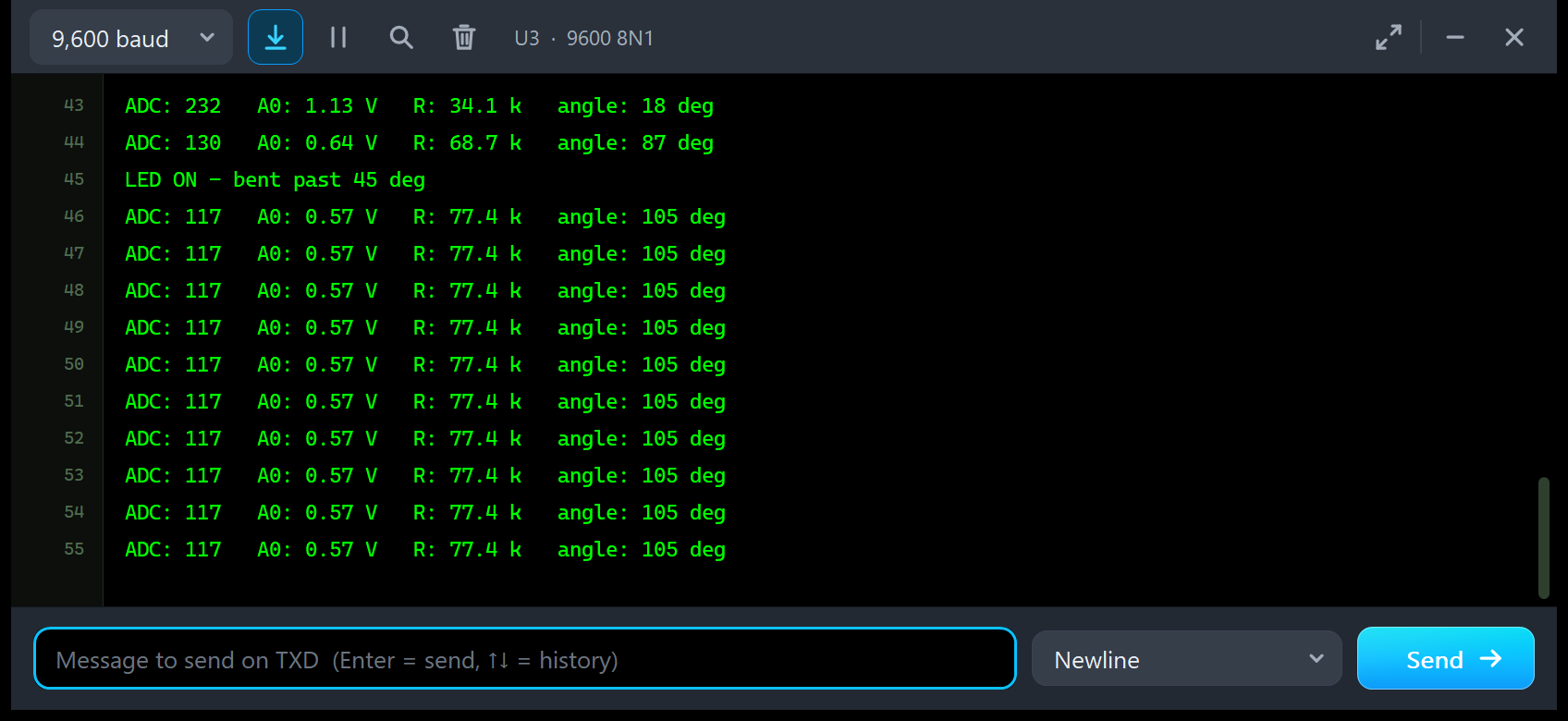
Click next to the strip, and it bends towards your click, in 5-degree steps: a click level with the bend gives 180 degrees, a click straight above the strip gives 0. In the image, one click gave 105 degrees. The display shows 77.5 k, the model's value; the sketch, from its ADC count of 117, prints 77.4 k and 105 degrees.
There is no box behind the strip: when its angle changes, the model asks Proteus to redraw the part, at most 12.5 times a second. Two grey corner marks on the right frame the area the strip can sweep; keep it free of other parts. In Proteus 8.5, FLEX SLOWLY ran smoothly on both sizes, with no flicker and no trails.
Flex Sensor Library for Proteus: Simple vs Advance
All three devices run the same model (TEPFLEX.DLL) with the same resistance law and properties. They differ in what they include and in their panel:
| Feature | Flex sensor (FLEXTEP) | Module Simple (FLEXMODTEP) | Module Advance (FLEXMODADVTEP) |
|---|---|---|---|
| Analog SPICE flex sensor, 2.2 or 4.5 inch, the strip that bends on the sheet | ✔ | ✔ | ✔ |
| Readings display and click-to-bend next to the strip | ✔ | ✔ | ✔ |
| Bare 2-pin sensor for your own divider (pins 1, 2) | ✔ | ✘ | ✘ |
| Module with the 10 k divider (VCC, OUT, GND), PWR and OUT LEDs | ✘ | ✔ | ✔ |
| FLEX SCENE panel on the schematic (red X, PANEL button) | ✔ | ✔ | ✘ |
| Pop-up window you can move, resize and minimise | ✘ | ✘ | ✔ |
| Flex page: measured values, 20 s chart, pin / event log | ✘ | ✘ | ✔ |
| Angle sweep, Divider, Bend step and Calibrate tools | ✘ | ✘ | ✔ |
| TEP Dark / Light theme, text size, Help page with Copy diagnostics | ✘ | ✘ | ✔ |
Choose the bare sensor when you want to build the divider yourself, the Module Simple to keep the controls beside your circuit, and the Module Advance when your sheet is full or you want hard numbers about your divider and your sketch. There is no Advance version of the bare sensor, because the test tools need the module's own divider. The demo uses the two modules.
Download Flex Sensor Library for Proteus
Click the button below to download Flex-Sensor-Library-for-Proteus-v3.0.zip (about 1.47 MB, without the C++ source code):
Flex Sensor Library for Proteus V3.0- README.txt: a detailed guide to the files, the wiring, the model, the test tools and real hardware.
- Proteus Library Files:
TEPFLEX.LIB(all three devices),TEPSERIALMON.LIBand our Arduino UNO libraryArduinoV3TEP.LIB/ArduinoV3TEP.IDX. - Proteus Model Files:
TEPFLEX.DLLandTEPSERIALMON.DLL. - Proteus Simulation:
FLEX-Angle-ArduinoUnoV3.pdsprj,Flex_Angle.hex(both UNOs run it) and copies of both DLLs. - Arduino Code:
Flex_Angle.ino, the demo sketch. It needs no Arduino library, onlyanalogRead(),digitalWrite()and Serial.
No Proteus yet? Read How to Download and Install Proteus 7 and 8. New to libraries? Follow How to Install a New Library in Proteus.
How to Install Flex Sensor Library for Proteus
- Close Proteus and extract the whole zip file to a normal folder, for example your Desktop.
- Copy the four files from Proteus Library Files into the LIBRARY folder, usually
C:\Program Files (x86)\Labcenter Electronics\Proteus 8 Professional\LIBRARY(on some PCsC:\ProgramData\Labcenter Electronics\Proteus 8 Professional\LIBRARY). - Copy
TEPFLEX.DLLandTEPSERIALMON.DLLfrom Proteus Model Files into the MODELS folder. - Delete
TEPFLEX.IDXfrom the LIBRARY folder if there is one; Proteus makes a new index. - Start Proteus, press P and search for FLEX. You get the three devices (category Sensors > Flex).
Used an earlier version? Earlier versions of our flex sensor library may use other file names; you can keep them. If a design still shows an old symbol, replace TEPFLEX.LIB, delete TEPFLEX.IDX and re-pick the part. Tested in Proteus 8.5; Proteus 7 is not supported.
The Flex Sensor Module in Proteus
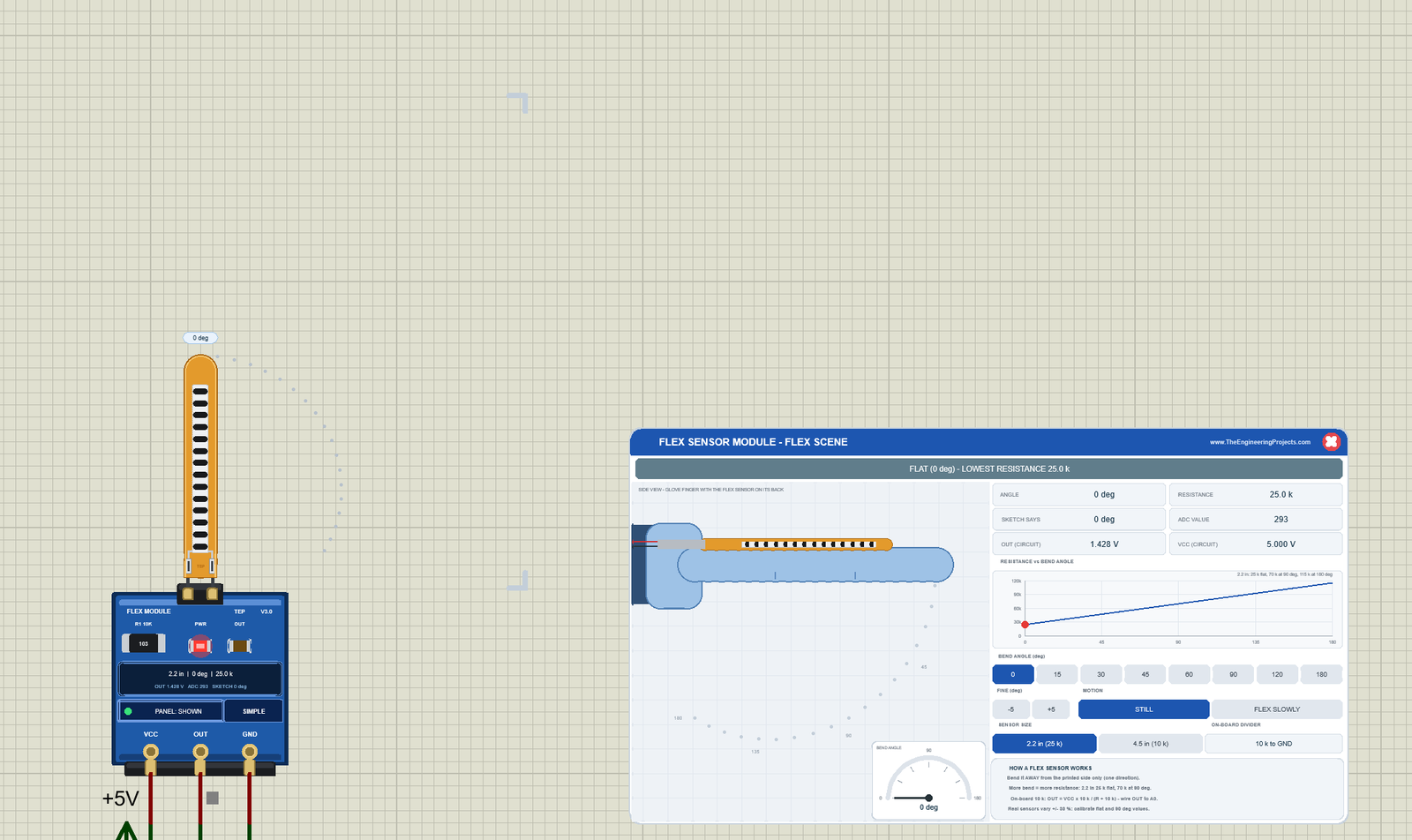
We drew the module as a small, clean TEP board in blue. The strip sits in J1, the black 2-pin header on its top edge. Below the "FLEX MODULE" print you see the 10 k divider resistor R1 (marked "103"), the red PWR LED, the OUT LED, a dark readings display, the PANEL button, the SIMPLE badge and the pins VCC, OUT and GND. Here is U1, the Module Simple, flat at the start of a run:
Pinout
| Pin | What it does | Demo connection |
|---|---|---|
| VCC (module) | Supply of the divider and the PWR LED | +5V terminal |
| OUT (module) | The divider's middle point; it falls as the sensor bends | Arduino A0 |
| GND (module) | Ground | GND |
| 1 (bare sensor) | One end of the flex resistor | 5V (in your own divider) |
| 2 (bare sensor) | The other end | A0, with a 10 k resistor from A0 to GND |
LEDs and Indicators
| Indicator | What it shows |
|---|---|
| PWR LED (red) | Lit while the module has power (the real module's LED; in the model also a real 1.5 k load) |
| OUT LED (amber) | Lit while OUT changes, that is while the sensor moves |
| Readings display | The size, the angle and the resistance ("2.2 in | 0 deg | 25.0 k"), then OUT, the ADC count and the angle the demo sketch prints |
| Blue arc, grey dots, angle label | The path the tip has swept, the rest of its path and the angle at the tip |
| Corner marks | The area the strip can sweep |
| PANEL: SHOWN / CLOSED, OPEN PANEL | The panel button (Simple) or the pop-up button (Advance), with a status dot |
| SIMPLE / ADVANCE | The device badge |
Only the PWR LED is on a real module. The OUT LED, the readings display, the arc and the angle label are TEP additions.
The Bare Flex Sensor (FLEXTEP)
The third device is the flex sensor alone: the same amber strip with its pins 1 and 2 at the bottom, a small name, the readings display, the PANEL button and the badge. Wire it with a 10 k resistor (Proteus's RES part) as shown in the pin table. Its FLEX SCENE panel assumes the divider set in the DIVR property, at 5 V.
Component Properties
| Property | Meaning | Default |
|---|---|---|
| SIZE | The sensor size: 2.2 or 4.5 (inch) | 2.2 |
| ANGLE | The bend at the start of a run, 0 to 180 deg | 0 |
| MOTION | STILL, or FLEX (flex slowly) at the start | STILL |
| FLATR | The flat resistance (ohm, e.g. 30k), or AUTO = by size | AUTO |
| BENDR | The resistance at 90 deg (ohm), or AUTO = by size | AUTO |
| DIVR | The module's on-board divider resistor; for the bare sensor, the divider its readouts assume | 10k |
| PERIOD | The FLEX SLOWLY period, 1 to 60 s | 4 |
| PANEL | Simple devices only: the scene panel at the start, OPEN or CLOSED | OPEN |
Ohm values accept 25000, 25k, 4k7, 1.2M, 470R or "10k ohm", from 100 ohm to 10 M. Every Run starts again from these properties; a bad value is logged and the default is used. With FLATR and BENDR you can simulate your own sensor, for example a 2.2 inch one that reads 30 to 40 k flat.
Flex Sensor Simple: The FLEX SCENE Panel on the Sheet
Beside the Simple module sits the FLEX SENSOR MODULE - FLEX SCENE panel (on the right of the image above). It shows a gloved finger from the side with the flex strip on its back, so you see what bends the sensor in a real data glove:
| Part | What it does |
|---|---|
| Header, red X | The panel name; the X closes the panel |
| Status banner | FLAT, BENT, FULLY BENT, FLEX SLOWLY, MOVING or NO POWER, each in its own colour |
| Side view | The glove finger with the amber strip on its back, and the fingertip's dotted path from 0 to 180 deg |
| BEND ANGLE dial | The angle on a small gauge |
| Readouts | ANGLE, RESISTANCE, SKETCH SAYS (the angle the demo sketch prints), ADC VALUE, and OUT (CIRCUIT) and VCC (CIRCUIT), measured in the circuit |
| RESISTANCE vs BEND ANGLE | The sensor's straight line with a red dot at the present angle |
| BEND ANGLE buttons | 0, 15, 30, 45, 60, 90, 120 and 180 deg |
| FINE | -5 / +5 deg |
| MOTION | STILL or FLEX SLOWLY |
| SENSOR SIZE | 2.2 in (25 k) or 4.5 in (10 k) |
| ON-BOARD DIVIDER | The module's divider: 10 k to GND |
| HOW A FLEX SENSOR WORKS | Four short tips about the sensor and its divider |
In the flat image, the banner says FLAT (0 deg) - LOWEST RESISTANCE 25.0 k, and the readouts agree with the board display: OUT 1.428 V, ADC 293, SKETCH SAYS 0 deg. OUT and VCC (5.000 V) come from the circuit that Proteus solved, not from a formula.
Bending to 90 Degrees
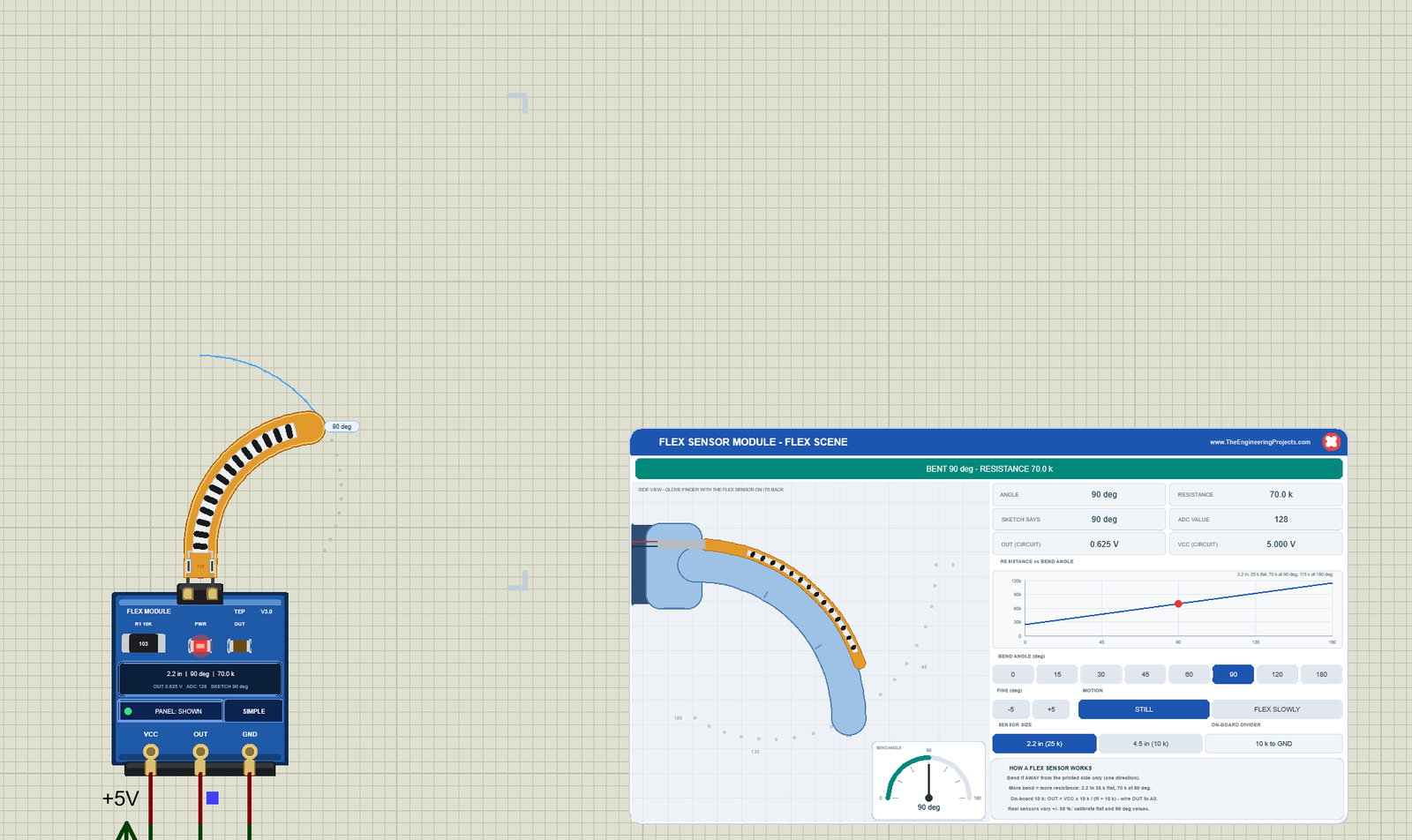
Click 90 in the BEND ANGLE row. The finger and the strip bend together in about half a second; the finger moves smoothly at about 200 degrees per second, so the resistance never jumps. The banner turns teal: BENT 90 deg - RESISTANCE 70.0 k. OUT drops to 0.625 V and the ADC to 128. On the sheet, the strip curls until its tip points sideways, and the blue arc shows the quarter circle the tip travelled. The sketch on UNO 1 now prints 90 degrees and lights the green LED D1.
FLEX SLOWLY: a Finger That Keeps Bending
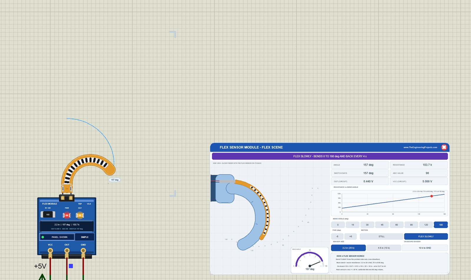
Click 180, then FLEX SLOWLY. The finger now bends from 0 to the selected angle and back every 4 seconds (the PERIOD property), like a hand that opens and closes, and the banner turns violet. The image caught the strip at 157 degrees: 103.7 k, OUT 0.440 V, ADC 90, and the sketch says 157. The amber OUT LED is lit, because OUT keeps changing. This is the best way to test code that has to follow a moving finger.
The 4.5 Inch Sensor at 180 Degrees
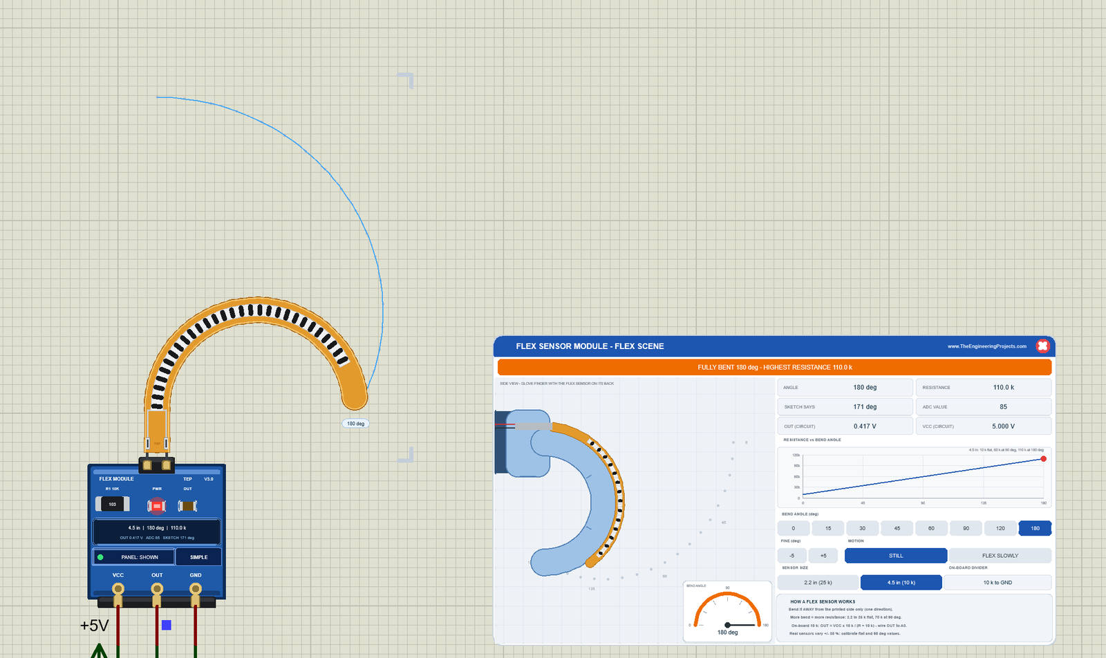
Click 4.5 in (10 k) and 180. The strip becomes the long sensor with its 29 bars and bends into a half circle, and the banner turns orange: FULLY BENT 180 deg - HIGHEST RESISTANCE 110.0 k. OUT is 0.417 V and the ADC 85. But SKETCH SAYS 171 deg, not 180.
That is not a bug; it is a lesson. The demo sketch is calibrated for the 2.2 inch sensor (25 k flat, 70 k at 90 degrees), and the 4.5 inch sensor has another line (10 k flat, 60 k at 90 degrees). When you swap the sensor, calibrate again: type CAL FLAT and CAL BENT, or FLAT 10000 and BENT 60000, as the sketch's comment says.
Closing the Panel
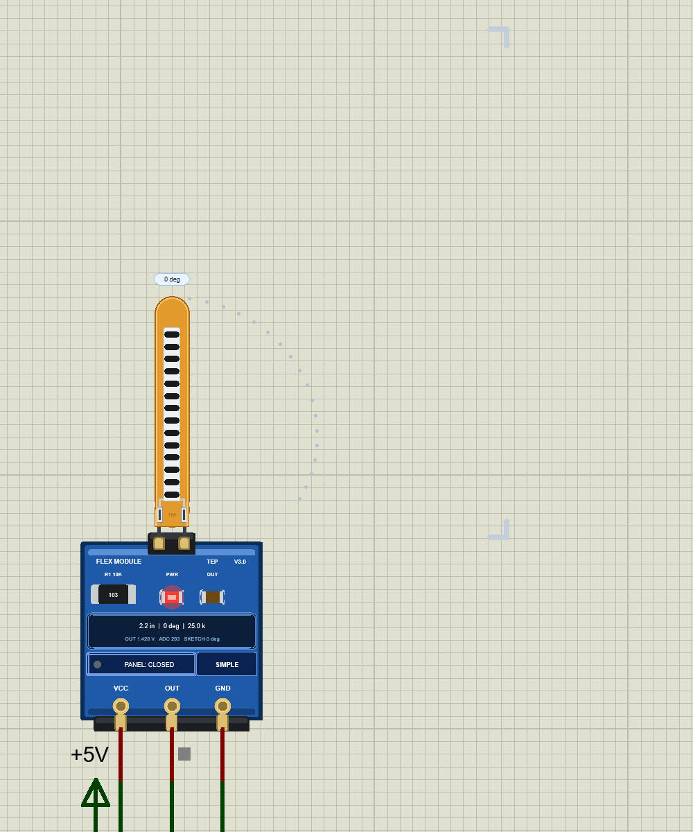
Click the red X in the panel header: the panel disappears, and the board button says PANEL: CLOSED with a grey dot. The sensor keeps working, and the two corner marks of the strip's area are easy to see. Click PANEL to bring the scene back; the PANEL property sets how a run starts.
Flex Sensor Advance: The Pop-Up Window
The Advance device keeps only the module on the schematic, with an OPEN PANEL button and the ADVANCE badge. Here is U2, bent to 90 degrees:
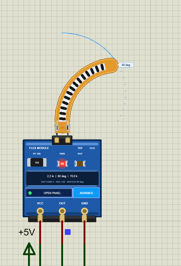
At Run, the TEP Flex Sensor Advance pop-up opens, with the look of our TEP Serial Monitor and no Windows title bar: move it by its header, resize or minimise it. The header shows the state (U2 · BENT 90 deg), the Flex and Test tabs and the palette (theme), gear (Settings) and ? (Help) icons. Below it, chips show BENT, the ADC count with the angle the sketch makes of it (128, 90 deg), R 70.0 k, the size and the divider.
The Flex Page
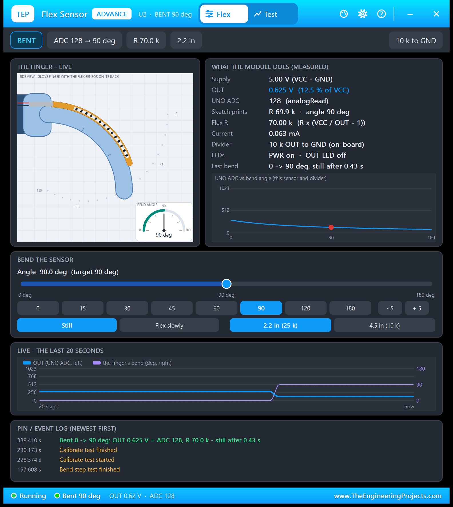
- THE FINGER - LIVE: the glove finger with the amber strip, and the BEND ANGLE dial.
- WHAT THE MODULE DOES (MEASURED): Supply 5.00 V, OUT 0.625 V (12.5 % of VCC), UNO ADC 128, Sketch prints R 69.9 k and 90 deg, Flex R 70.00 k (from the node voltages), Current 0.063 mA, the on-board 10 k divider, the LEDs, and the last bend: 0 to 90 deg, still after 0.43 s.
- UNO ADC vs bend angle: the count curve for this sensor and divider, with a red dot.
- BEND THE SENSOR: an angle slider, the presets, - 5 / + 5, Still or Flex slowly, and the size.
- LIVE - THE LAST 20 SECONDS: the ADC (blue) and the finger's bend (violet). The step is my click on 90: the bend rose, the ADC fell.
- PIN / EVENT LOG: the newest line records that bend at 338.410 s (OUT 0.625 V = ADC 128, R 70.0 k, still after 0.43 s), above the tests I ran before.
The current is easy to check: 5 V / (70 k + 10 k) = 0.0625 mA. And 0.43 s is the finger's smooth 90-degree move.
FLEX SLOWLY on the 4.5 Inch Sensor
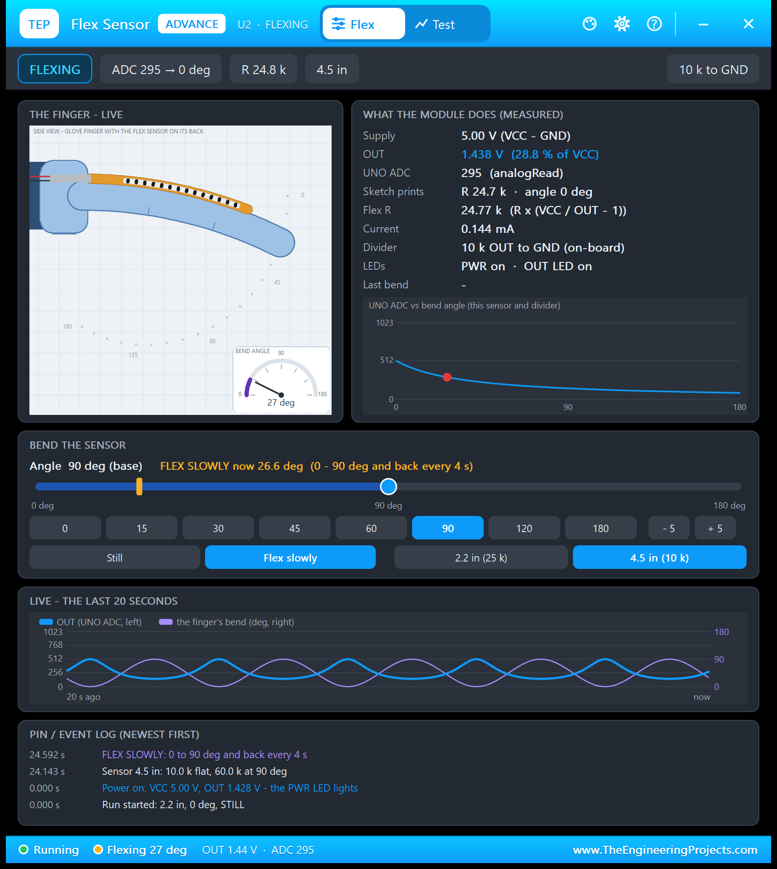
Here I clicked 4.5 in (10 k) and Flex slowly. While the finger flexes, the slider keeps your angle, "Angle 90 deg (base)", and an amber marker shows where the finger is now: FLEX SLOWLY now 26.6 deg (0 - 90 deg and back every 4 s). The chart shows two waves in opposite phase, and the event log lists the run start, the power-on (VCC 5.00 V, OUT 1.428 V), the sensor change (4.5 in: 10.0 k flat, 60.0 k at 90 deg) and FLEX SLOWLY. At 26.6 degrees the 4.5 inch sensor has 24.77 k, about the 2.2 inch sensor's flat value, so the 2.2 inch sketch prints 0 deg: the same calibration lesson.
The Test Page: Four Measured Flex Sensor Test Tools
The Test tab has four tools. A tool moves the sensor only with the panel's own actions (the bend angle and, for two tools, the finger speed or the divider resistor) and reads the OUT and VCC voltages that Proteus's SPICE solver computes at every step. So every number is measured on the running circuit, with the simulation clock. Each tool puts your bend back when it ends, says why when it cannot start (no power, another test running) and ends with a bold "Good for:" line. All results below come from U2 in Proteus 8.5.
1. Angle Sweep: the Whole OUT Curve
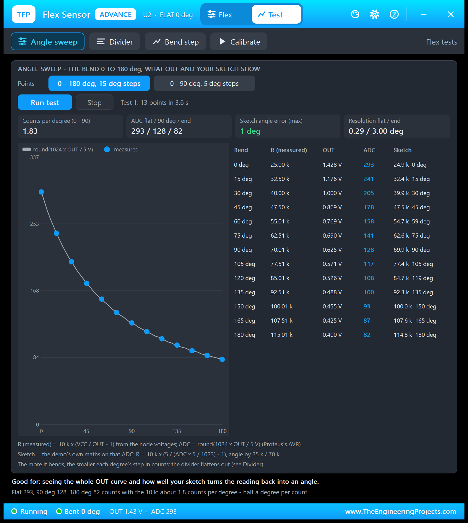
Good for: "seeing the whole OUT curve and how well your sketch turns the reading back into an angle." Choose 0 - 180 deg, 15 deg steps or 0 - 90 deg, 5 deg steps and click Run test. At each angle, the tool waits for a flat OUT, averages it and lists what the circuit and the demo sketch make of it:
| Bend | R (measured) | OUT | ADC | The sketch prints |
|---|---|---|---|---|
| 0 deg | 25.00 k | 1.428 V | 293 | 24.9 k, 0 deg |
| 15 deg | 32.50 k | 1.176 V | 241 | 32.4 k, 15 deg |
| 30 deg | 40.00 k | 1.000 V | 205 | 39.9 k, 30 deg |
| 45 deg | 47.50 k | 0.869 V | 178 | 47.5 k, 45 deg |
| 60 deg | 55.01 k | 0.769 V | 158 | 54.7 k, 59 deg |
| 75 deg | 62.51 k | 0.690 V | 141 | 62.6 k, 75 deg |
| 90 deg | 70.01 k | 0.625 V | 128 | 69.9 k, 90 deg |
| 105 deg | 77.51 k | 0.571 V | 117 | 77.4 k, 105 deg |
| 120 deg | 85.01 k | 0.526 V | 108 | 84.7 k, 119 deg |
| 135 deg | 92.51 k | 0.488 V | 100 | 92.3 k, 135 deg |
| 150 deg | 100.01 k | 0.455 V | 93 | 100.0 k, 150 deg |
| 165 deg | 107.51 k | 0.425 V | 87 | 107.6 k, 165 deg |
| 180 deg | 115.01 k | 0.400 V | 82 | 114.8 k, 180 deg |
The tiles sum it up: 1.83 counts per degree from 0 to 90, a sketch angle error of 1 degree at most (60 prints 59, 120 prints 119), and a resolution of 0.29 deg per count near flat but 3.00 deg near the end. The curve flattens out as the sensor bends, so a 10 k divider reads small bends well and big bends poorly. The next tool shows how to do better.
2. Divider: Which Resistor Reads the Bend Best?
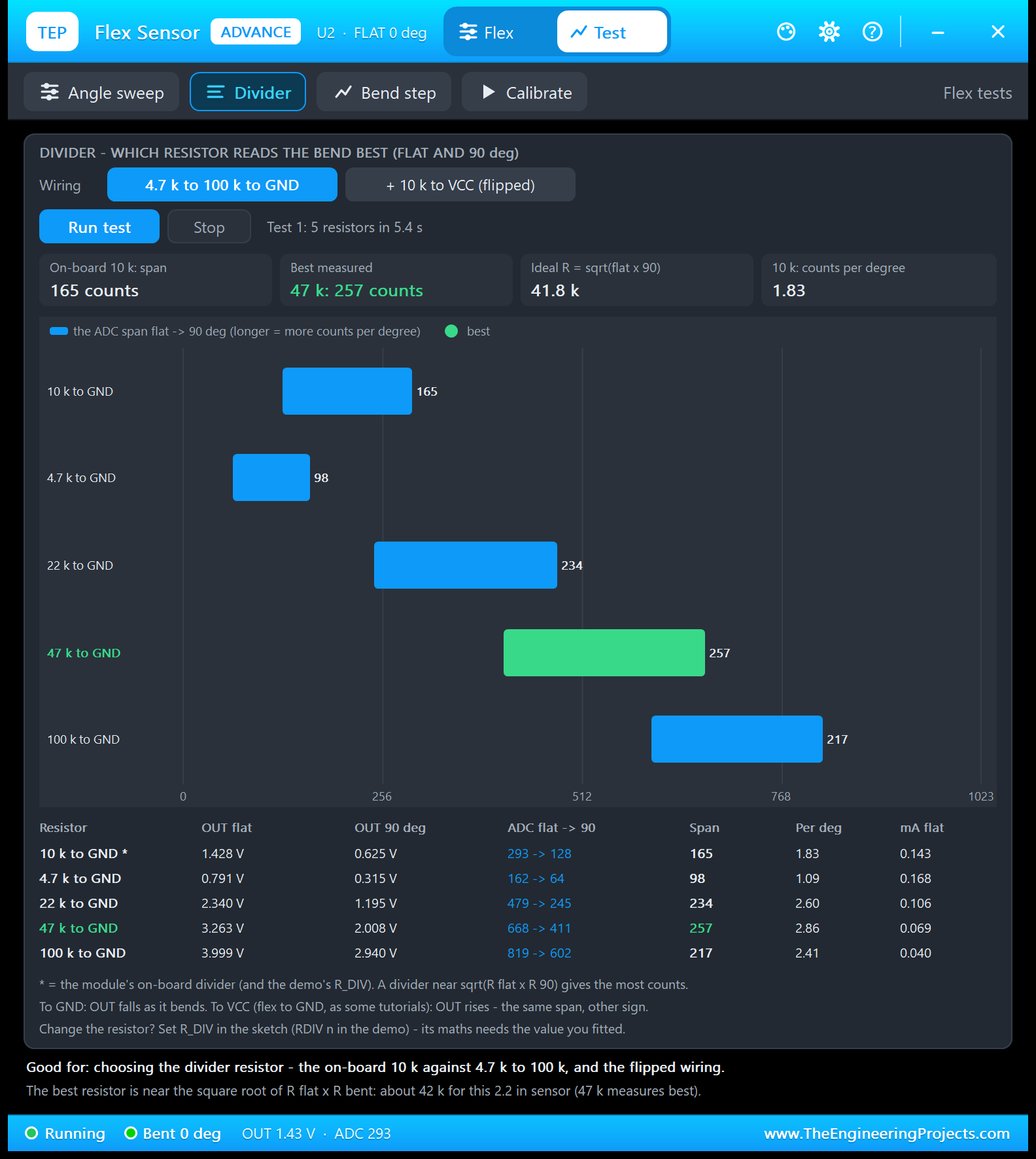
Good for: "choosing the divider resistor - the on-board 10 k against 4.7 k to 100 k, and the flipped wiring." The tool swaps the module's divider resistor for each value, reads OUT flat and at 90 degrees, and puts the 10 k back afterwards:
| Resistor | OUT flat | OUT 90 deg | ADC flat to 90 | Span | Per deg | mA flat |
|---|---|---|---|---|---|---|
| 10 k to GND * | 1.428 V | 0.625 V | 293 to 128 | 165 | 1.83 | 0.143 |
| 4.7 k to GND | 0.791 V | 0.315 V | 162 to 64 | 98 | 1.09 | 0.168 |
| 22 k to GND | 2.340 V | 1.195 V | 479 to 245 | 234 | 2.60 | 0.106 |
| 47 k to GND | 3.263 V | 2.008 V | 668 to 411 | 257 | 2.86 | 0.069 |
| 100 k to GND | 3.999 V | 2.940 V | 819 to 602 | 217 | 2.41 | 0.040 |
The span is the number of counts between flat and 90 degrees: the longer, the more counts per degree. The on-board 10 k gives 165, 47 k the most, 257. The rule: the best divider is near the square root of (R flat x R 90), here 41.8 k, and 47 k is the nearest common value. It also draws less current: 0.069 mA instead of 0.143 mA.
The second button, + 10 k to VCC (flipped), tests the 10 k on top and the flex sensor to GND: then OUT rises with the bend (the README lists 731 to 896, the same 165 counts). If you change the resistor, tell the sketch: RDIV 47000 in the demo, or R_DIV.
3. Bend Step: How Fast Does OUT Follow a Finger?
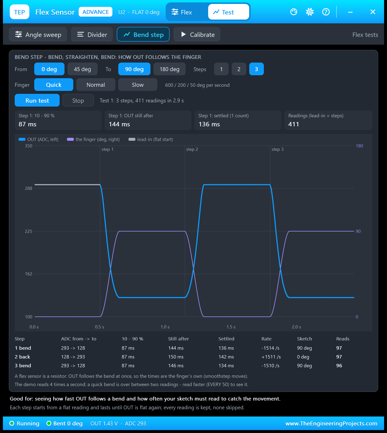
Good for: "seeing how fast OUT follows a bend and how often your sketch must read to catch the movement." Choose the start (0 or 45 deg), the end (90 or 180 deg), the finger (Quick 600, Normal 200 or Slow 50 deg per second) and 1 to 3 steps (bend, straighten, bend). Each step starts from a flat reading (the grey lead-in) and lasts until OUT is flat again; every reading is kept. I ran 0 to 90 deg, Quick, 3 steps:
| Step | ADC | 10 - 90 % | Still after | Settled (1 count) | Rate | Reads |
|---|---|---|---|---|---|---|
| 1 bend | 293 to 128 | 87 ms | 144 ms | 136 ms | -1514 /s | 97 |
| 2 back | 128 to 293 | 87 ms | 150 ms | 142 ms | +1511 /s | 97 |
| 3 bend | 293 to 128 | 87 ms | 146 ms | 134 ms | -1510 /s | 96 |
A flex sensor is a resistor: OUT follows the bend at once, so these times are the finger's own smooth move. With the Normal finger, the README lists 261 ms from 10 to 90 % and a still ADC after 430 ms. The important part for your sketch: the demo reads 4 times a second, so a quick bend is over between two readings. To see the movement, read faster: type EVERY 50.
4. Calibrate: the Two Numbers Every Flex Sketch Needs
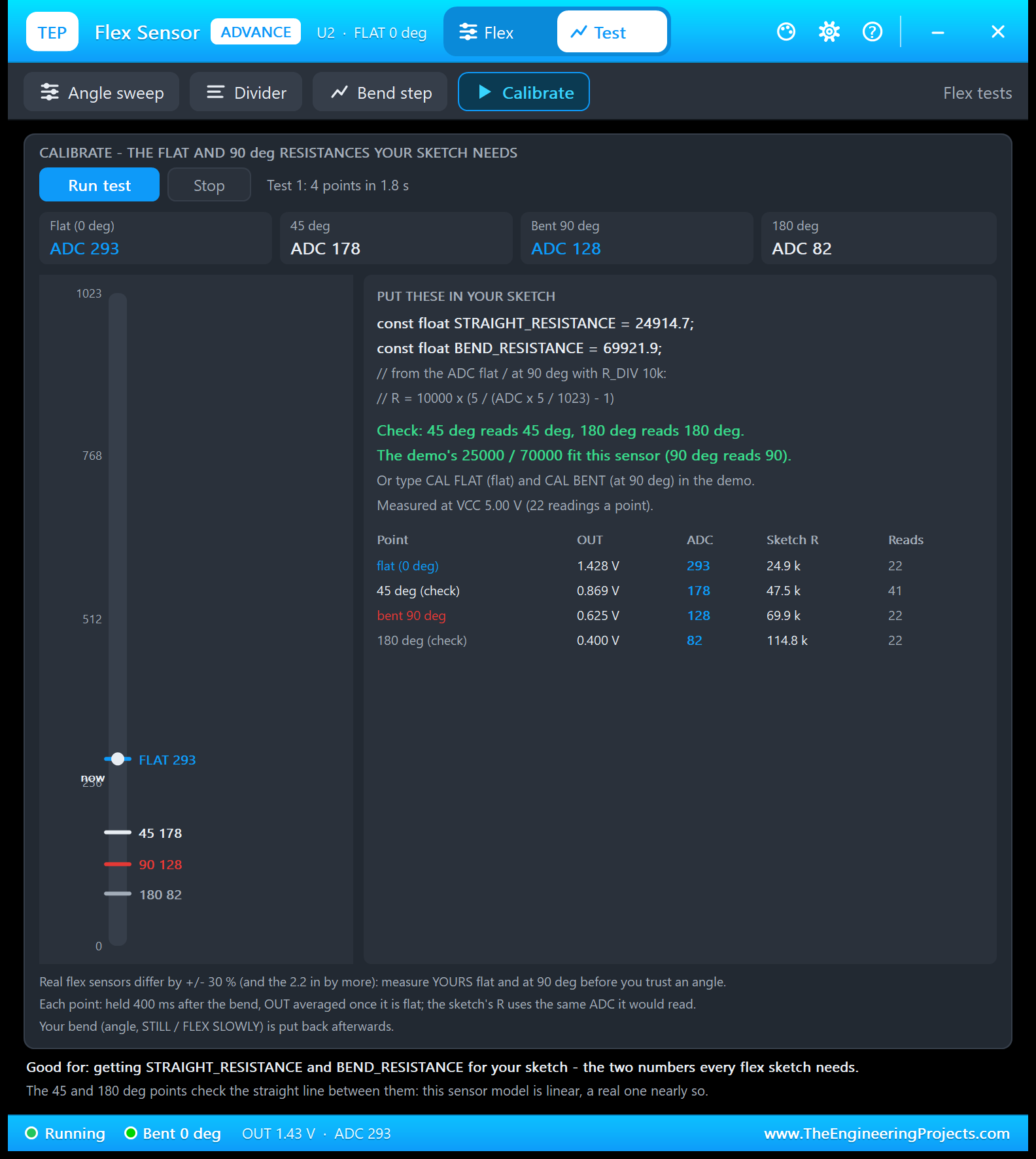
Good for: "getting STRAIGHT_RESISTANCE and BEND_RESISTANCE for your sketch - the two numbers every flex sketch needs." The tool holds the sensor flat, at 45, 90 and 180 degrees (400 ms each) and reads 293, 178, 128 and 82. From the flat and the 90-degree count, it writes the two lines to paste:
const float STRAIGHT_RESISTANCE = 24914.7;
const float BEND_RESISTANCE = 69921.9;
The 45 and 180 degree points check the line: 45 deg reads 45, 180 deg reads 180. Why 24914.7 and not 25000? The sketch's maths starts from the ADC count, and Proteus rounds 292.6 counts to 293, so these are exactly the values your sketch computes. In the demo, CAL FLAT and CAL BENT give the same numbers.
Settings and Help
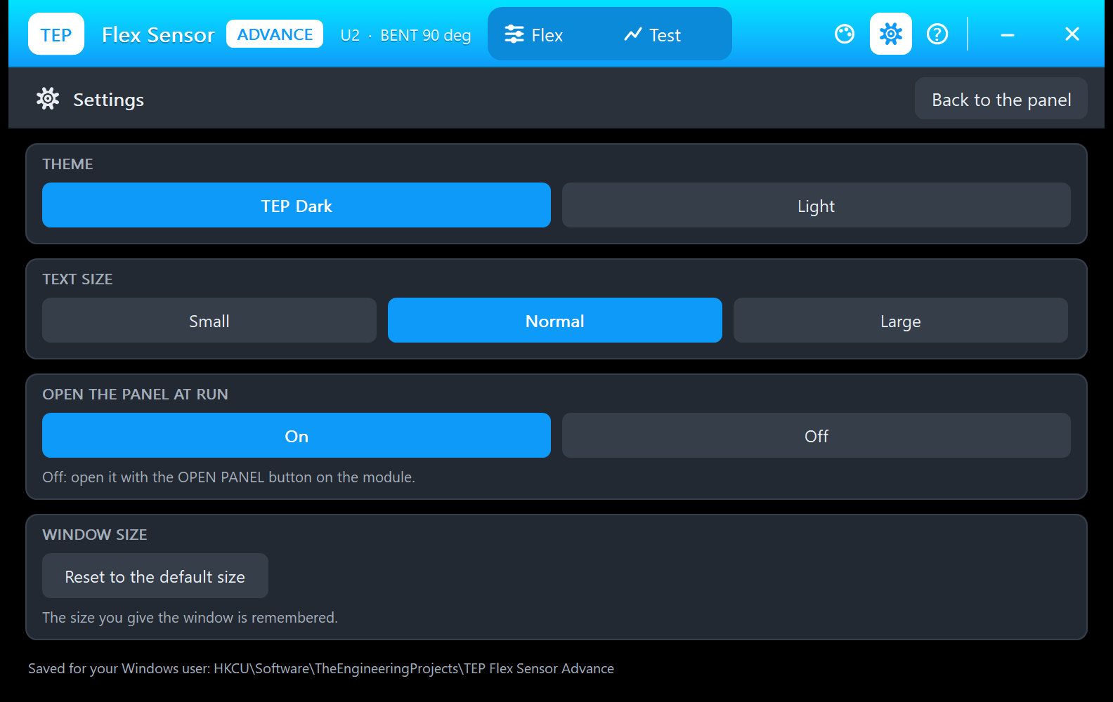
The gear opens Settings: the theme (TEP Dark or Light), the text size, open the panel at Run (with Off, use OPEN PANEL) and a window size reset, saved for your Windows user.
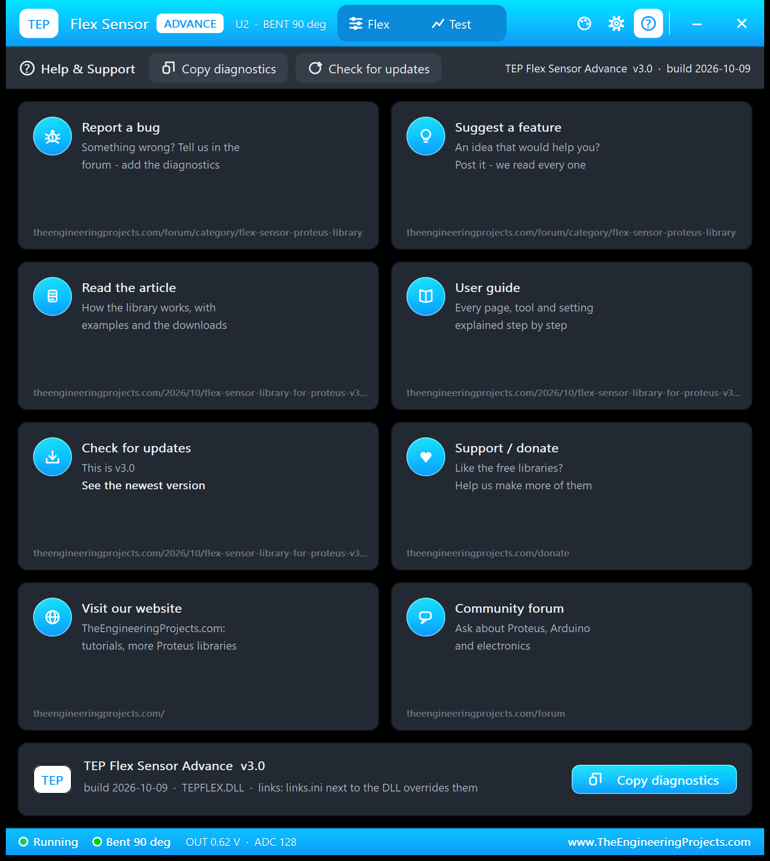
The ? icon opens Help & Support: eight cards with their links (bugs and ideas in the flex sensor board of our forum, this article and user guide, updates, donate, website, forum) and Copy diagnostics for a bug report. A links.ini file next to the DLL can change the links.
Flex Sensor with Arduino in Proteus
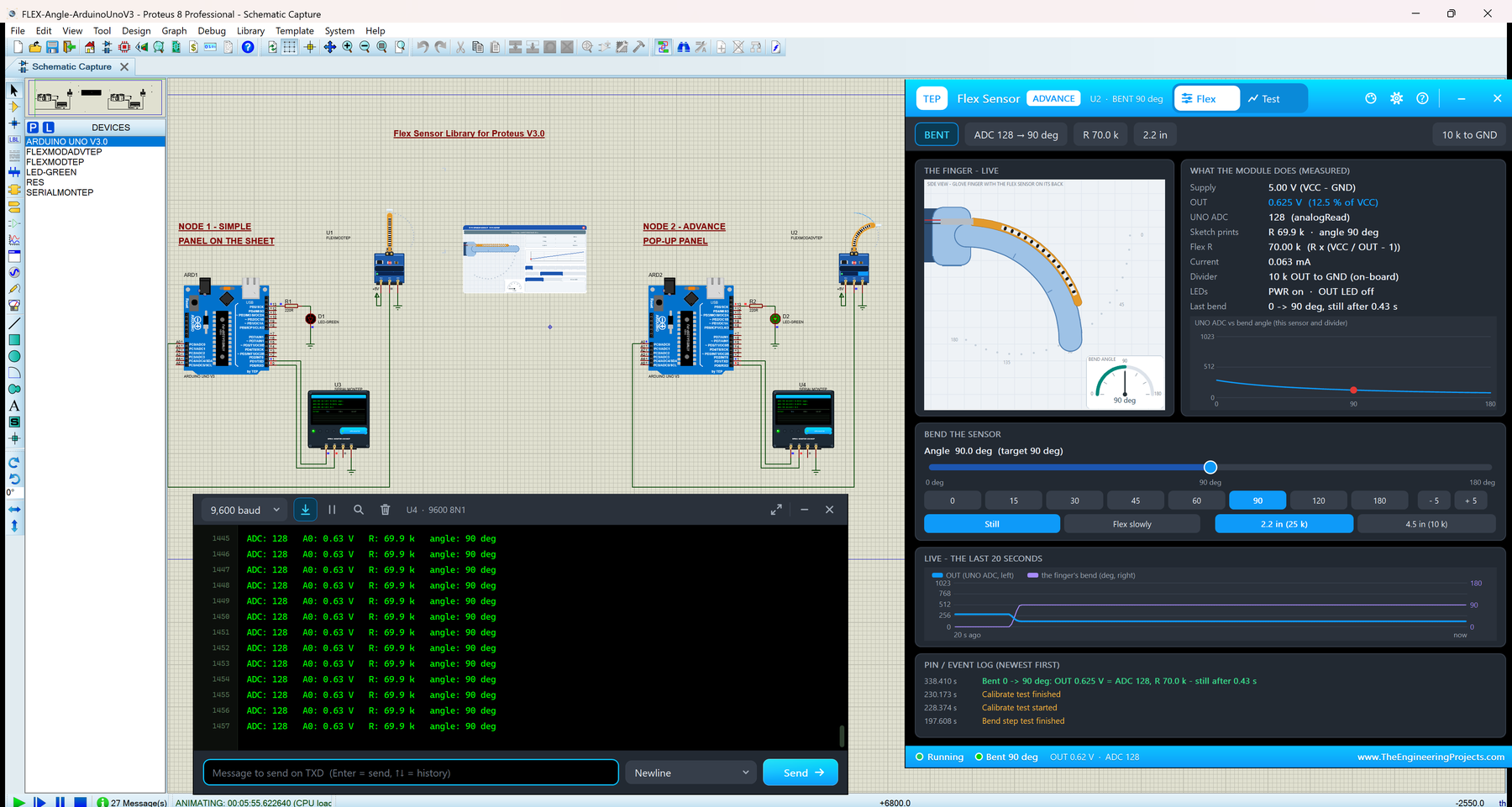
Open FLEX-Angle-ArduinoUnoV3.pdsprj from the Proteus Simulation folder, with Flex_Angle.hex and both DLLs beside it. Its two Arduino UNOs from our Arduino Library for Proteus V3.0 run the same HEX file:
- NODE 1 - SIMPLE, PANEL ON THE SHEET: UNO 1 (ARD1) with the Flex Sensor Module Simple (U1), the green bend LED D1 with R1 (220R) on D13, and Serial Monitor U3.
- NODE 2 - ADVANCE, POP-UP PANEL: UNO 2 (ARD2) with the Flex Sensor Module Advance (U2), the bend LED D2 with R2 (220R) on D13, and Serial Monitor U4.
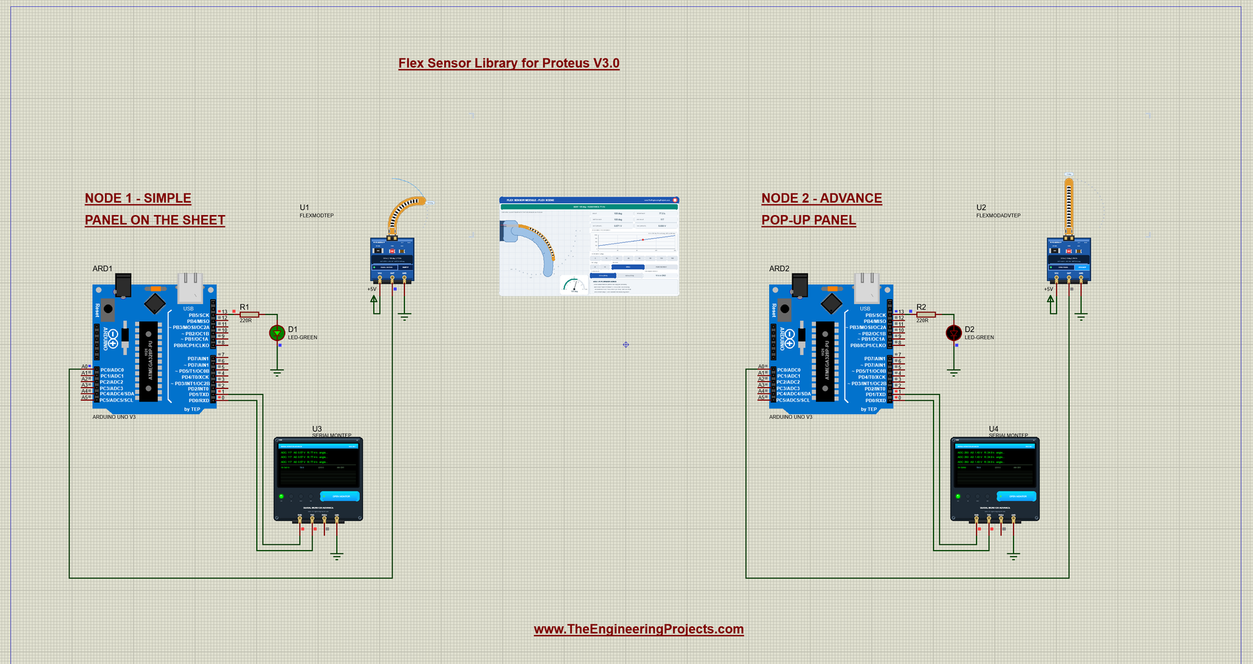
In this run, I clicked right of U1's strip: it bent to 105 degrees, U1's FLEX SCENE panel (in the middle) switched to BENT 105 deg, and D1 lit. U2 stayed flat, so D2 is off.
Wiring
| From | To | Why |
|---|---|---|
| Module VCC / GND | +5V terminal / ground | Power (the PWR LED lights) |
| Module OUT | Arduino A0 | The divider voltage |
| LED + 220 Ω | D13 to GND | The bend LED (on a real UNO, D13 also drives the board's own LED) |
| Serial Monitor RXD / TXD / GND | Arduino D1 / D0 / ground | Shows what the Arduino prints, sends what you type |
| Serial Monitor RXD2 | Not connected | The sensor sends no serial data |
A0 is the first analog input of the UNO (see our Introduction to Arduino UNO).
The Arduino Code
The sketch Flex_Angle.ino uses no library. It starts with the pins, the supply and the divider:
const int FLEX_PIN = A0;               // the divider's middle point goes to A0
const int LED_PIN = 13;                // lights while the sensor is bent past LED_ANGLE

const float VCC = 5.0;                 // supply voltage of the divider (the UNO's 5V)
float R_DIV = 10000.0;                 // the fixed resistor from A0 to GND (10k)
Then the calibration, as variables, so the CAL FLAT and CAL BENT commands can change them:
// Calibration: the sensor's resistance when it is flat and when it is bent 90 degrees.
// Spectra Symbol 2.2 inch: 25k flat, about 70k at 90 deg (the Proteus model's defaults).
// For the 4.5 inch sensor use 10000.0 and 60000.0.  Real sensors vary +/- 30 % - measure yours!
float STRAIGHT_RESISTANCE = 25000.0;
float BEND_RESISTANCE = 70000.0;
setup() starts the serial port at 9600 baud and prints the welcome lines:
void setup() {
  Serial.begin(9600);
  pinMode(LED_PIN, OUTPUT);
  Serial.println("TEP Flex Sensor demo - www.TheEngineeringProjects.com");
  Serial.println("Bend the finger on the Proteus panel and watch the angle.");
  Serial.println("Type HELP for the commands.");
  Serial.println();
}
Each reading starts by reading A0 and turning the count into volts:
  // 1. Read the voltage on A0 (0 .. 1023 for 0 .. 5 V)
  int raw = analogRead(FLEX_PIN);
  float volts = raw * VCC / 1023.0;
  lastAdc = raw;
Then the divider maths, backwards: the resistance from the voltage...
float resistance = R_DIV * (VCC / volts - 1.0);...and the angle; a negative angle becomes 0:
  // 3. Turn the resistance into an angle: straight line between "flat = 0 deg" and "bent = 90 deg"
  float angle = (resistance - STRAIGHT_RESISTANCE) * 90.0 / (BEND_RESISTANCE - STRAIGHT_RESISTANCE);
  if (angle < 0) angle = 0;            // a flex sensor only bends one way
One line on the Serial Monitor:
  Serial.print("ADC: ");
  Serial.print(raw);
  Serial.print("   A0: ");
  Serial.print(volts, 2);
  Serial.print(" V   R: ");
  Serial.print(resistance / 1000.0, 1);
  Serial.print(" k   angle: ");
  Serial.print(angle, 0);
  Serial.println(" deg");
The bend LED: on from LED_ANGLE (45 deg), with one message when it switches:
  // 5. The LED: on while the sensor is bent past LED_ANGLE as printed (a message when it changes)
  bool bent = LED_ANGLE > 0 && angle + 0.5 >= LED_ANGLE;
  if (bent != ledOn) {
    ledOn = bent;
    digitalWrite(LED_PIN, bent ? HIGH : LOW);
    Serial.print(bent ? "LED ON - bent past " : "LED OFF - below ");
    Serial.print(LED_ANGLE);
    Serial.println(" deg");
  }
HELP prints two short lines, which fit the Simple interface of the Serial Monitor:
void printHelp() {
  Serial.println("Commands: HELP, STATUS, READ, EVERY ms (0 = pause), LED deg,");
  Serial.println("  CAL FLAT, CAL BENT, FLAT ohms, BENT ohms, RDIV ohms");
}
CAL FLAT measures the sensor and stores STRAIGHT_RESISTANCE (CAL BENT does the same for BEND_RESISTANCE):
  } else if (strcmp(cmd, "CAL FLAT") == 0) {
    float r = measureNow();
    if (r < 0) return;
    STRAIGHT_RESISTANCE = r;
    Serial.print("STRAIGHT_RESISTANCE = ");
    Serial.print(r, 0);
    Serial.println(" (the sensor is flat now)");
    checkCalibration();
The loop reads a command line and takes a reading every everyMs ms, with millis() instead of delay(), so commands get their answer at once:
  if (everyMs > 0 && millis() - lastRead >= everyMs) {   // the readings (millis, not delay: commands stay quick)
    lastRead = millis();
    readSensor();
  }
Everything lives in RAM, so a new Run brings back the start values. To change the sketch, export a new HEX file and load it into both UNOs; see How to get the HEX file from Arduino. New to Arduino? Start with our Arduino Tutorial for Beginners.
Serial Monitor Commands
| Command | What it does |
|---|---|
| HELP | The command list (two lines) |
| STATUS | Two lines: the calibration, R_DIV and the reading interval; then the LED and the last reading |
| READ | One reading now |
| EVERY ms | The reading interval in ms (start: 250; 0 = pause, READ still works) |
| LED deg | The bend LED on D13 lights from this angle (default 45, 0 = never) |
| CAL FLAT | The sensor is flat now: this reading becomes STRAIGHT_RESISTANCE |
| CAL BENT | The sensor is bent 90 deg now: it becomes BEND_RESISTANCE |
| FLAT ohms, BENT ohms | Set the two resistances by hand |
| RDIV ohms | Your divider resistor (10000 on the module) |
How to Run the Demo
- Press Run. Both Serial Monitors (9600 baud) and U2's pop-up open, and both monitors print ADC 293.
- On U1's panel, click 90: the ADC drops to 128 and D1 lights. Click right of the strip, then try FLEX SLOWLY and 4.5 in.
- On U3, click STATUS, READ, EVERY 1000 and EVERY 250.
- Calibrate U2: with U2 flat, click CAL FLAT on U4; with U2 bent to 90 deg, click CAL BENT.
- On U2, try the Flex page and the four tools on the Test tab.
Flex Sensor Proteus Simulation Results
The Serial Monitor in Its Simple Interface
Both monitors in this demo run in the Simple interface of our TEP Serial Monitor, as in every monitor screenshot here. Only the log, the send box and one slim toolbar row stay visible (baud rate, follow, pause, search and clear), so the window stays small.
- Switch to it: right-click the log and choose Simple interface, or press Ctrl+Shift+U.
- Back to the full view: click the corner button (the expand arrows at the top right), press Esc or Ctrl+Shift+U, or right-click and choose Full interface.
- Your choice is remembered.
Type commands in the send box and press Enter; the quick buttons come back with the full view. Every line the demo prints is 80 characters or less. Read all about the monitor in TEP Serial Monitor Advance for Proteus.
Start-Up
After Run, U3 and U4 print the welcome lines and a reading four times a second (the README's expected output):
TEP Flex Sensor demo - www.TheEngineeringProjects.com
Bend the finger on the Proteus panel and watch the angle.
Type HELP for the commands.

ADC: 293   A0: 1.43 V   R: 24.9 k   angle: 0 deg
ADC: 293   A0: 1.43 V   R: 24.9 k   angle: 0 deg
A Click Next to the Strip
ADC: 232   A0: 1.13 V   R: 34.1 k   angle: 18 deg
ADC: 130   A0: 0.64 V   R: 68.7 k   angle: 87 deg
LED ON - bent past 45 deg
ADC: 117   A0: 0.57 V   R: 77.4 k   angle: 105 deg
ADC: 117   A0: 0.57 V   R: 77.4 k   angle: 105 deg
ADC: 117   A0: 0.57 V   R: 77.4 k   angle: 105 deg
One click right of the strip asked for 105 degrees. The finger needs about half a second for that, so two readings caught it on the way: 18 deg and 87 deg. The 87-degree reading was past 45 degrees, so the sketch printed "LED ON - bent past 45 deg" and lit D1. Then every line reads ADC 117, 0.57 V, 77.4 k and 105 deg.
Bent 90 Degrees on U4
ADC: 128   A0: 0.63 V   R: 69.9 k   angle: 90 deg
ADC: 128   A0: 0.63 V   R: 69.9 k   angle: 90 deg
ADC: 128   A0: 0.63 V   R: 69.9 k   angle: 90 deg
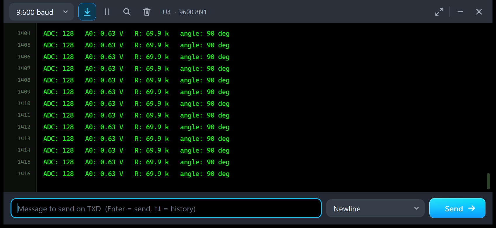
U4 shows U2 at 90 degrees: ADC 128, 0.63 V, 69.9 k and 90 deg, exactly what the pop-up's "Sketch prints" line showed.
STATUS and Calibration
STATUS answers in two lines; here is the README's example, with U1 at 180 degrees:
Status: flat 25000 R, bent 70000 R, R_DIV 10000 R, every 250 ms
  LED from 45 deg (ON), last ADC 82 = 114.8 k = 180 deg
And with U2 flat, CAL FLAT, then bent to 90 degrees, CAL BENT, U4 prints (README):
STRAIGHT_RESISTANCE = 24915 (the sensor is flat now)
BEND_RESISTANCE = 69922 (the sensor is bent 90 deg now)
These are the Calibrate tool's 24914.7 and 69921.9, rounded to whole ohms.
Troubleshooting
- The sketch prints "ADC: 0" and "no signal on A0 - check the wiring": the module has no power. Check VCC and GND; the PWR LED must be lit, and the display says NO POWER.
- A piece of an older strip picture stays on the sheet while the strip bends: the design holds an older TEPFLEX.LIB symbol (the Simulation Log says so). Replace TEPFLEX.LIB, delete TEPFLEX.IDX and re-pick the part.
- The angle is a degree off (60 reads 59): the ADC moves in whole counts; calibrate, and the error stays within about 1 degree.
- The angles are far off after you changed the divider or the sensor: set R_DIV (RDIV n) and calibrate again.
- The reading rises instead of falls: your divider is the other way round (10 k to VCC); the demo's formula assumes the flex sensor on top.
- The panel's buttons do nothing during a test: the tool owns the bend; wait, or click Stop.
- The part is not simulated, or no monitor window: TEPFLEX.DLL or TEPSERIALMON.DLL is missing from MODELS and the project folder; click OPEN MONITOR on a closed monitor.
- The Advance pop-up does not appear: click OPEN PANEL on the module, or turn "Open the panel at Run" back on in Settings.
- The red X does not close the Simple panel: the LIBRARY folder holds an older TEPFLEX.LIB; replace it, delete TEPFLEX.IDX and re-pick the part.
Things to Know Before Using a Real Flex Sensor
The demo sketch uses only analogRead(), digitalWrite() and Serial, so it runs on a real UNO with a real flex sensor, too. Keep in mind:
- Bend it the right way: bend the sensor away from its printed (ink) side only, and never at its base, where it kinks. Clamp the base and let only the sensing length bend.
- Every sensor is different: real flex sensors differ by ±30 %, and a 2.2 inch sensor often reads 30 to 40 k flat. Calibrate yours flat and at 90 degrees, and put the divider you fitted into the sketch (RDIV).
- Choose the divider: about 42 k suits a 25 k / 70 k sensor; 47 k reads 257 counts from flat to 90 degrees, the module's 10 k only 165.
- Supply: A0 is ratiometric, and the sketch assumes 5 V, so power the divider from the UNO's 5V pin.
- Real UNO vs Proteus: a real ATmega328P truncates the ADC (flat: 292, 25.0 k), Proteus rounds (293, 24.9 k).
- Creep and hysteresis: a real reading drifts a little after a bend and differs between bending and straightening, so leave some margin in your thresholds.
Limitations of the Simulation
- Modelled: a SPICE resistor that follows the bend (a straight line from 0 to 180 degrees, one direction, both sizes, your own FLATR / BENDR), the divider and PWR LED load, a ratiometric OUT, smooth finger motion, and the UNO's ADC as Proteus converts it.
- Not modelled: creep and hysteresis, bending the wrong way, temperature, the ±30 % spread (set FLATR / BENDR instead) and wear.
- The model is our own implementation, written from the Spectra Symbol datasheets; it contains no third-party code. The HEX file contains the Arduino AVR core 1.8.6, which includes LGPL-licensed code; its source is on GitHub.
- Tested in Proteus 8.5 in October 2026 (the demo, the strip, the four tools and every screenshot here; about 0.43 x real time with the pop-up open and both monitors running) and with 3,025 automatic PC checks, all passed, 49 of them with the real demo sketch on two UNOs. Proteus 7 is not supported.
Want another analog sensor whose resistance changes? See our LDR Sensor Library for Proteus, where light does what the bend does here. For two analog axes and a push button, try our Joystick Module Library for Proteus.
So, that was all about the Flex Sensor Library for Proteus V3.0. I hope the amber strip that bends on your sheet and the four test tools make the flex sensor easy to understand, so your glove or robot hand works the first time you wire a real sensor. If you use the Flex Sensor Library for Proteus in a project, please share your feedback in the comments or in our forum, and if you have any questions, ask in the comments and I will help you out. Till the next tutorial, take care and have fun!