Hello friends, I hope you all are doing great. Today, I am going to share the new HC-05 & HC-06 Bluetooth Library for Proteus V1.1. The HC-05 and HC-06 are two of the most popular Bluetooth modules among Arduino users. They work like a wireless serial cable between your Arduino and a smartphone (or another module), so students use them for phone-controlled LEDs, robots and home automation. With this HC-05 Library for Proteus, you can try all of that before you buy a single module.
In this new version, you get four devices in one library: HC-05 Simple, HC-05 Advance, HC-06 Simple and HC-06 Advance. The Simple devices draw a virtual smartphone on the schematic; the Advance devices open a pop-up window with the phone and Bluetooth test tools. I am also sharing two complete Arduino HC-05 Proteus simulations: an LED switched from the phone, and an HC-05 master chatting with an HC-06 slave.
NOTICE: We are really proud of this one. As far as we know, our team is the first to design such libraries for Proteus: working HC-05 and HC-06 modules with a virtual smartphone, real master / slave pairing and Bluetooth test tools, right inside the simulation. It took our team a lot of hard work, many test runs and many design changes, and this library is a tribute to that effort. Your feedback is the fuel that keeps us going, so please tell us what you think in the comments below or in the Proteus Libraries category of our forum. And if our free libraries help you in your studies or work, you can buy us a coffee (our donation page is coming soon). So, let's get started with the HC-05 Library for Proteus:
What are the HC-05 and HC-06 Bluetooth Modules?
The HC-05 and HC-06 are small Bluetooth serial port modules built around the CSR BC417 chip. They use the Bluetooth Serial Port Profile (the "SPP" printed on the board), and your Arduino talks to them over a UART (the two-wire TX / RX serial port used by Serial). Whatever the Arduino writes into RXD comes out on the phone's screen, or on the TXD pin of another module.
Most people buy them on the blue ZS-040 breakout board with a gold PCB antenna.
HC-05 vs HC-06: What is the Difference?
They look almost the same, but the HC-05 can be a master (it searches and connects) or a slave (it waits for a phone or a master), while the HC-06 is slave only. The differences, as modelled in our library:
| Feature | HC-05 | HC-06 |
|---|---|---|
| Role | Master or slave (AT+ROLE) | Slave only |
| Pins (real order) | STATE RXD TXD GND VCC EN | RXD TXD GND VCC |
| EN (KEY) pin | Yes: HIGH = AT command mode | No |
| STATE pin | Yes: HIGH while connected | No |
| AT command set | Full set with queries (AT+NAME?, AT+ROLE? ...) | linvor set, no read commands |
| Firmware in the model | 2.0-20100601 | linvorV1.8 |
| Default data speed | 9600 bps (full AT mode: 38400) | 9600 bps |
AT Command Mode and the EN (KEY) Pin
AT commands are short text commands that start with "AT", such as AT+NAME? (what is your name?). They read and change the module's settings:
- HC-05, EN high at power-up: "full" AT mode at 38400 bps until AT+RESET or a power cycle. The classic beginner trap: data is 9600, but this AT mode is 38400.
- HC-05, EN high while running: "mini" AT mode at the data speed (9600) until EN goes low; the link stays up. Every HC-05 command ends with CR LF ("Both NL & CR" in the Arduino Serial Monitor).
- HC-06: no AT pin. While nothing is connected, everything on RXD is a command; while connected, AT commands are passed on as data.
What's New in HC-05 & HC-06 Library for Proteus V1.1
- Four devices: HC-05 Simple (
HC05TEP), HC-05 Advance (HC05ADVTEP), HC-06 Simple (HC06TEP) and HC-06 Advance (HC06ADVTEP), all on one model (TEPBLUETOOTH.DLL). - One library file:
TEPBLUETOOTH.LIBreplaces TEPHC05.LIB and TEPHC06.LIB; the old device names still work. - Board: a green PWR LED, a PCB antenna that glows blue on every byte over the air, a PANEL / OPEN PANEL button and a SIMPLE / ADVANCE badge. The STATE LED keeps the real blink patterns.
- Test tools in the Advance pop-up: connection test, round-trip test, AT check and link check.
- TEP Serial Monitor in the demos instead of the Virtual Terminal; each demo shows both styles.
- Smarter chat sketch: the master sends lines starting with AT to its own HC-05.
- Lighter package: about 1.4 MB, without the C++ source code.
HC-05 and HC-06 Library for Proteus: Simple vs Advance
Each module comes in two styles. Inside, it is the same model; only the panel differs:
| Feature | Simple | Advance |
|---|---|---|
| Full HC-05 / HC-06 model (both AT sets, EN, STATE, PIN pairing, BIND / CMODE) | ✔ | ✔ |
| STATE and PWR LEDs, antenna glow, animated waves | ✔ | ✔ |
| Virtual phone drawn on the schematic | ✔ | ✘ |
| Phone in a pop-up window you can move, resize and minimise | ✘ | ✔ |
| MODULE, LINK and TRAFFIC cards | ✘ | ✔ |
| Connection test and round-trip test | ✘ | ✔ |
| AT check and link check | ✘ | ✔ |
| TEP Dark / Light theme and text size | ✘ | ✔ |
| Help page with Copy diagnostics | ✘ | ✔ |
| Same device names as v1.0 (old designs keep working) | ✔ | ✘ |
Choose Simple to see everything on the sheet, and Advance for crowded sheets or to find out why a link fails. You can mix them; both demos do.
Download HC-05 Library for Proteus
This one download is also our HC-06 Library for Proteus, because both modules live in the same files. Click the button below to download HC-05-HC-06-Bluetooth-Library-for-Proteus-v1.1.zip:
Download HC-05 and HC-06 Library for Proteus V1.1- README.txt: a detailed guide to the files.
- Proteus Library Files:
TEPBLUETOOTH.LIB(all four devices),TEPSERIALMON.LIBand our Arduino UNO libraryArduinoV3TEP.LIB/ArduinoV3TEP.IDX. - Proteus Model Files:
TEPBLUETOOTH.DLLandTEPSERIALMON.DLL. - Proteus Simulation: the two demo projects, four .hex files and copies of both DLLs.
- Arduino Code: the four demo sketches and the AltSoftSerial 1.4 library (MIT licence).
If you don't have Proteus yet, read How to Download and Install Proteus 7 and 8. New to libraries? Follow How to Install a New Library in Proteus.
How to Install HC-05 Library for Proteus
- Close Proteus and extract the whole zip file.
- Copy the four files from Proteus Library Files into the LIBRARY folder, usually
C:\Program Files (x86)\Labcenter Electronics\Proteus 8 Professional\LIBRARY(on some PCsC:\ProgramData\Labcenter Electronics\Proteus 8 Professional\LIBRARY). - Copy
TEPBLUETOOTH.DLLandTEPSERIALMON.DLLinto the MODELS folder. - Start Proteus, press P and search for HC-05 or HC-06. You get the Simple and the Advance device of each (category Peripherals > Wireless).
Updating from v1.0? V1.1 replaces TEPHC05.LIB and TEPHC06.LIB with one TEPBLUETOOTH.LIB. Delete TEPHC05.LIB and TEPHC06.LIB, and any TEPHC05.IDX / TEPHC06.IDX, from the LIBRARY folder, or duplicate parts appear (two libraries with the same device names confuse Proteus). Then replace TEPBLUETOOTH.DLL in MODELS. The library was tested in Proteus 8.5; Proteus 7 is not supported.
HC-05 and HC-06 Modules in Proteus
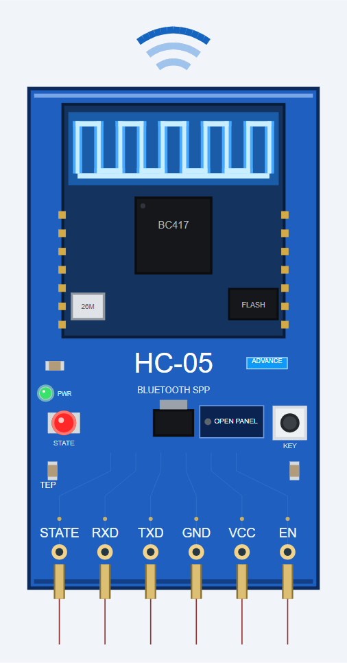
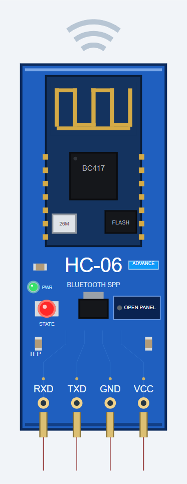
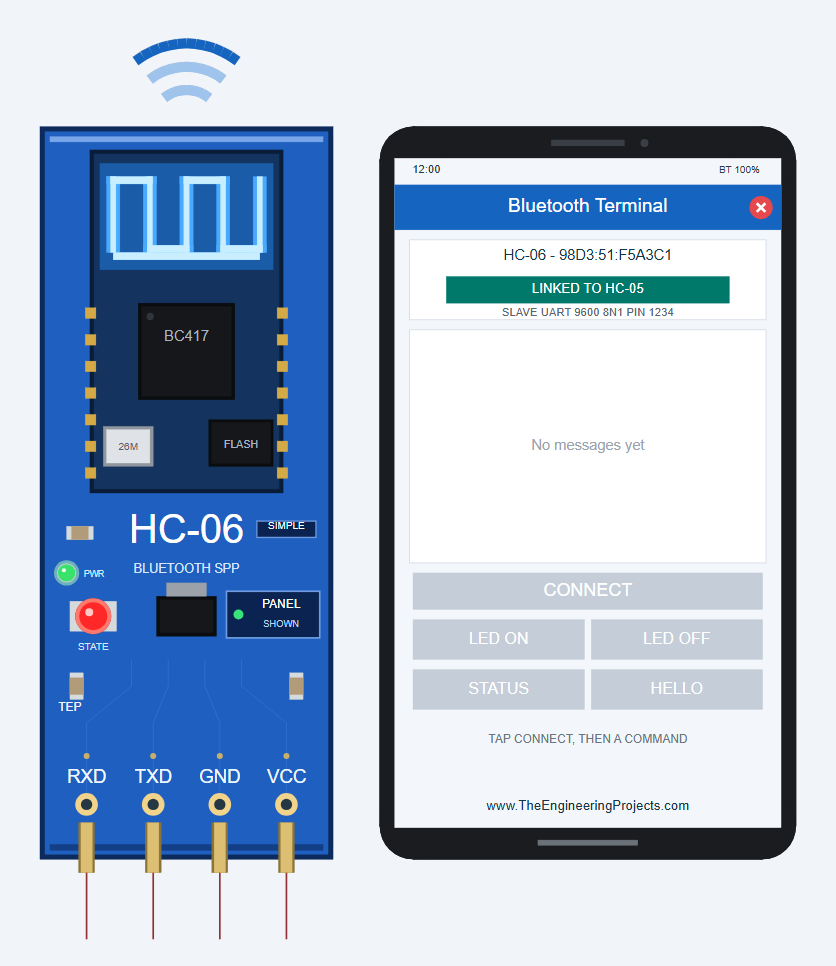
We designed both modules as clean TEP boards in the blue of the real ZS-040 breakout: the core module with its gold meander antenna, the BC417 chip, the red STATE LED and a big white module name. Here is the HC-05 Advance while linked, and the HC-06 Advance at rest:
Pinout
The pins are in the same order as on the real boards:
| Pin | Module | Function | Demo connection |
|---|---|---|---|
| STATE | HC-05 | Output: HIGH while connected | Arduino D12 |
| RXD | Both | Serial input (data or AT commands) | Arduino D9 |
| TXD | Both | Serial output (data and AT replies) | Arduino D8 |
| GND | Both | Ground | GND |
| VCC | Both | Power supply | +5 V |
| EN | HC-05 | HIGH = AT command mode (also called KEY) | Arduino D7 (chat demo) |
STATE LED, PWR LED, Antenna Glow and Waves
| Indicator | What it shows |
|---|---|
| STATE LED (red), HC-05 | Fast blink while waiting, slow blink in AT mode, double blink when connected |
| STATE LED (red), HC-06 | Blinking while waiting, steady when connected |
| PWR LED (green) | On while VCC and GND are powered |
| PCB antenna (blue glow) | Glows blue while sending or receiving |
| Waves rippling outwards (dark blue) | Sending |
| Waves rippling inwards (light blue) | Receiving |
| Grey waves | Idle |
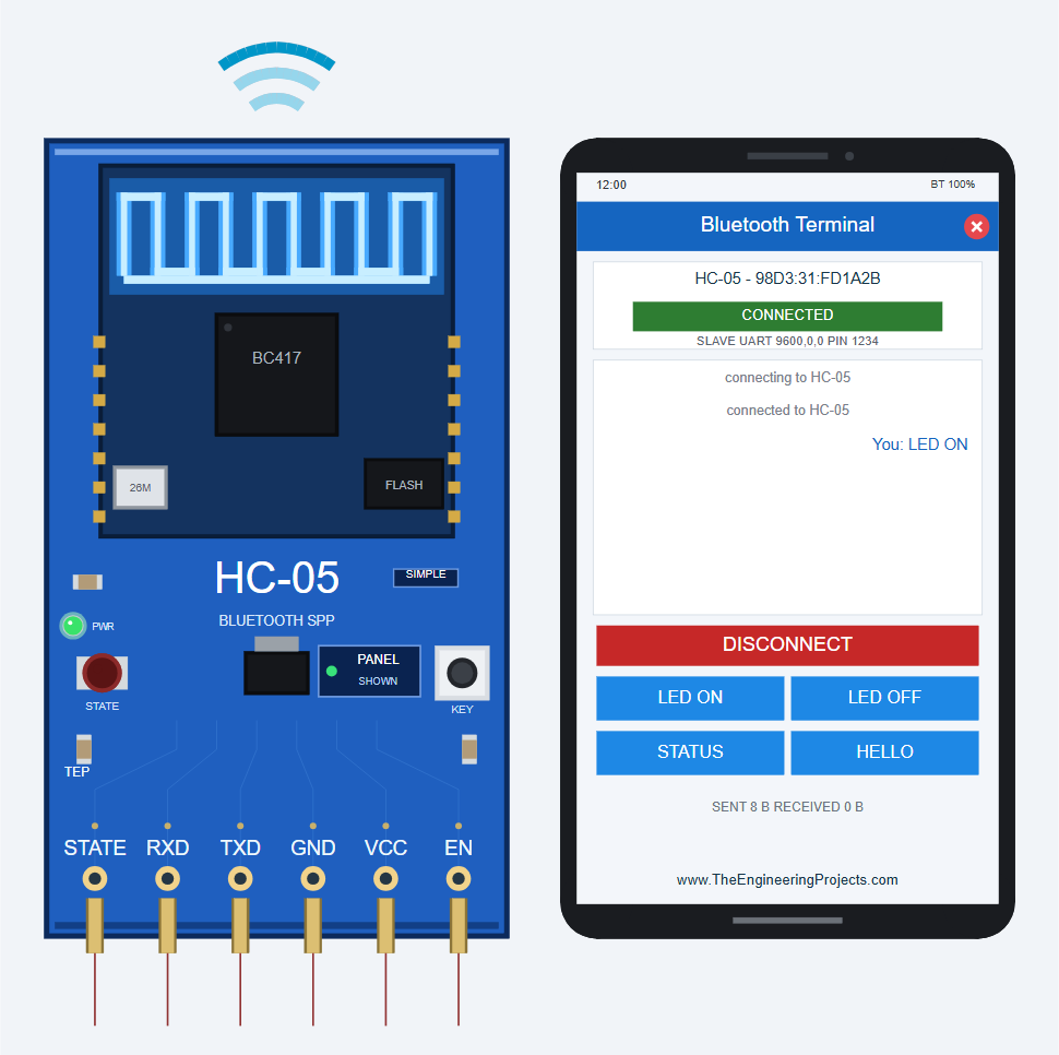
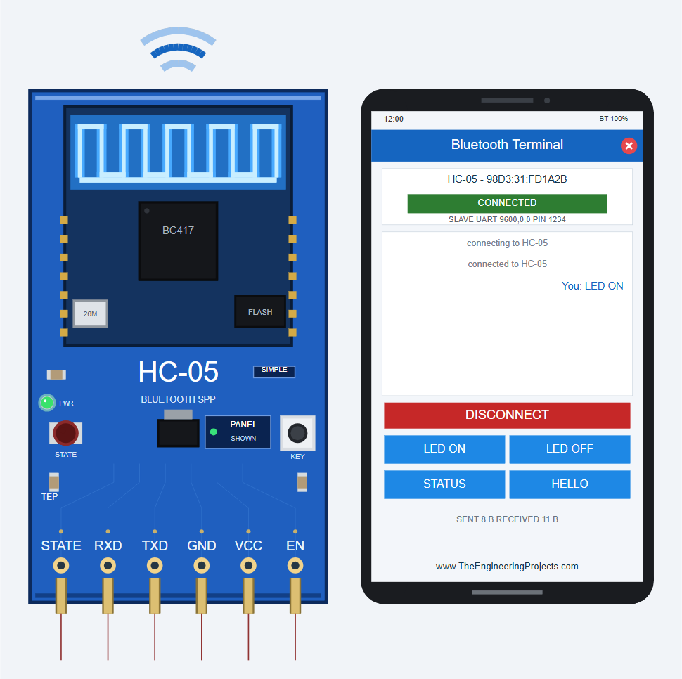
Here is the HC-05 Simple during one LED ON: first the phone's line arrives (receiving, SENT 8 B RECEIVED 0 B), then the Arduino's "LED is ON" goes back (sending, RECEIVED 11 B).
Badges and Buttons
A SIMPLE or ADVANCE badge shows which device you placed. The board button is PANEL on the Simple (green dot SHOWN, grey dot CLOSED) and OPEN PANEL on the Advance (green dot while the window is visible). The HC-05 also shows the KEY push-button of the real breakout; in the simulation, you switch AT mode with the EN pin.
Component Properties
Double-click the module to open Edit Properties. The properties are the same on Simple and Advance:
| Property | Meaning | Default |
|---|---|---|
| BTNAME | Bluetooth name | HC-05 / HC-06 |
| BTADDR | Bluetooth address (nap:uap:lap) | 98d3:31:fd1a2b / 98d3:51:f5a3c1 |
| BTPIN | PIN / password | 1234 |
| BTBAUD | Data UART baud rate | 9600 |
| BTROLE (HC-05) | Role: 0 slave, 1 master | 0 |
| BTCMODE (HC-05) | Connect mode: 0 BIND address, 1 any | 0 |
| BTBIND (HC-05) | BIND address (master) | 0:0:0 |
These are the settings stored in the module when the simulation starts; AT commands change them until the simulation stops.
The Virtual Phone: HC-05 / HC-06 Simple
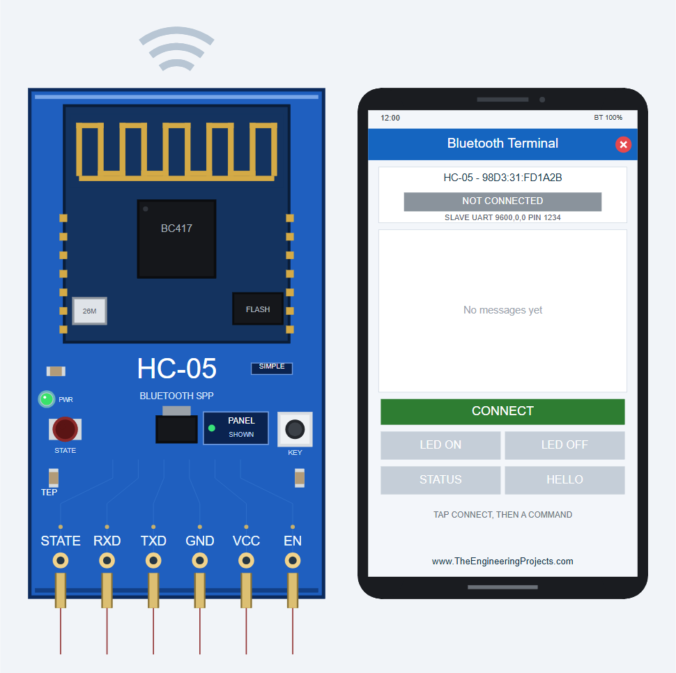
This is my favourite part. Beside each Simple module, we have drawn a smartphone running a "Bluetooth Terminal" app, so you can "use your phone" inside Proteus. Here it is before connecting:
Every Control on the Phone
| Part | What it does |
|---|---|
| Module card | Name, address, state chip, role, UART and PIN |
| State chip | NOT CONNECTED, CONNECTING..., CONNECTED, LINKED TO (another module), MASTER - SEARCHING, AT MODE (speed) or NO POWER |
| Conversation | "You: ..." is what the phone sent; "HC-05: ..." is what the Arduino sent back |
| CONNECT / DISCONNECT | Pairs with the module's PIN and connects, or disconnects |
| LED ON, LED OFF, STATUS, HELLO | Send that text, with CR LF at the end |
| Counter | Bytes sent and received, e.g. SENT 8 B RECEIVED 11 B |
The phone pairs with the module's own PIN. It cannot connect to a module that is a master, is in AT mode or is already linked to another module.
Connecting and Sending LED ON
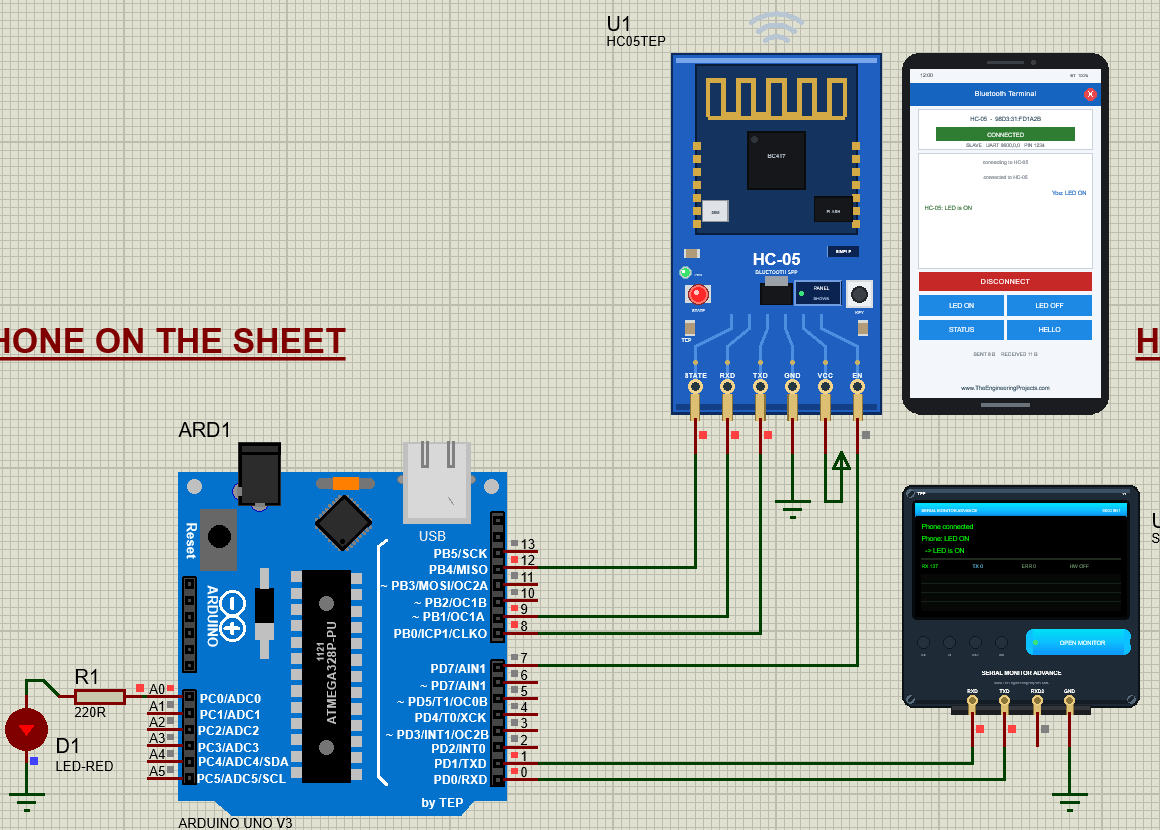
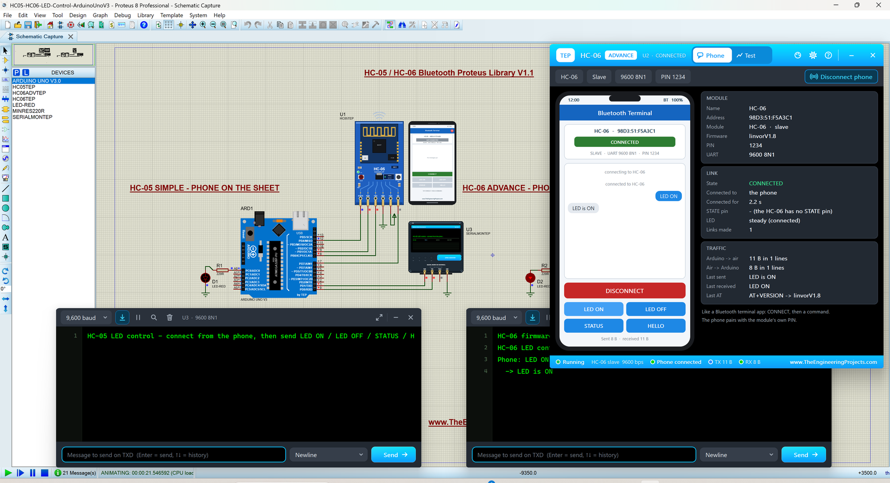
In the LED demo, click CONNECT. The chip shows CONNECTING..., then CONNECTED; the STATE LED starts its double blink and the STATE pin goes high. Now click LED ON: the LED on A0 lights, the phone shows "You: LED ON" and "HC-05: LED is ON", and the Serial Monitor U3 prints the same exchange:
This is exactly how the real thing works: a Bluetooth terminal app only sends lines of text, and your sketch decides what each line means.
Closing and Opening the Phone
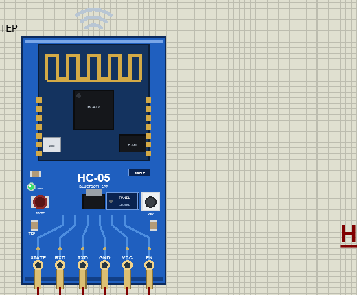
Need room on the sheet? Click the red X in the phone's blue title bar. Only the board stays, and the button now says CLOSED with a grey dot. Click PANEL to bring the phone back.
HC-05 / HC-06 Advance: The Pop-Up Panel
The Advance devices keep only the board on the schematic. At Run, a TEP pop-up window opens with the look of our TEP Serial Monitor; move it by its header, resize or minimise it, and reopen it with OPEN PANEL. The header shows the part and its state (U2 · CONNECTED), the tabs Phone and Test, and the theme, Settings (gear) and Help (?) icons; the toolbar chips show the name, role, UART and PIN.
The Phone Page
The Phone page shows the same phone, with the chat as blue (phone) and grey (Arduino) bubbles, beside three cards: MODULE (name, address, role, firmware, PIN, UART), LINK and TRAFFIC. Here is the HC-06 Advance of the LED demo after LED ON:
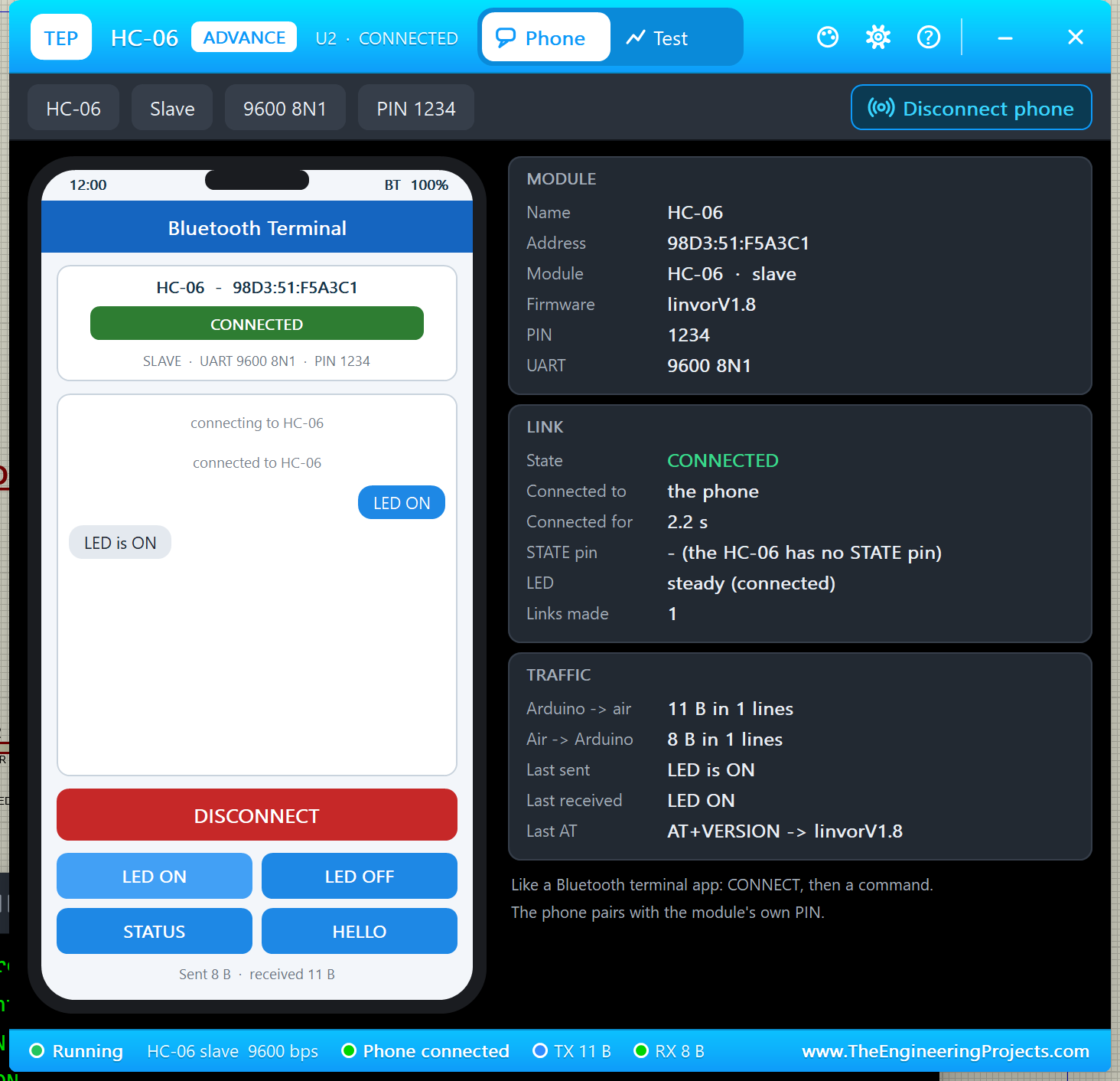
- LINK: CONNECTED to the phone for 2.2 s; STATE pin "- (the HC-06 has no STATE pin)"; LED steady (connected); links made 1.
- TRAFFIC: Arduino -> air 11 B ("LED is ON"), air -> Arduino 8 B ("LED ON"); last AT "AT+VERSION -> linvorV1.8" from the sketch's start-up.
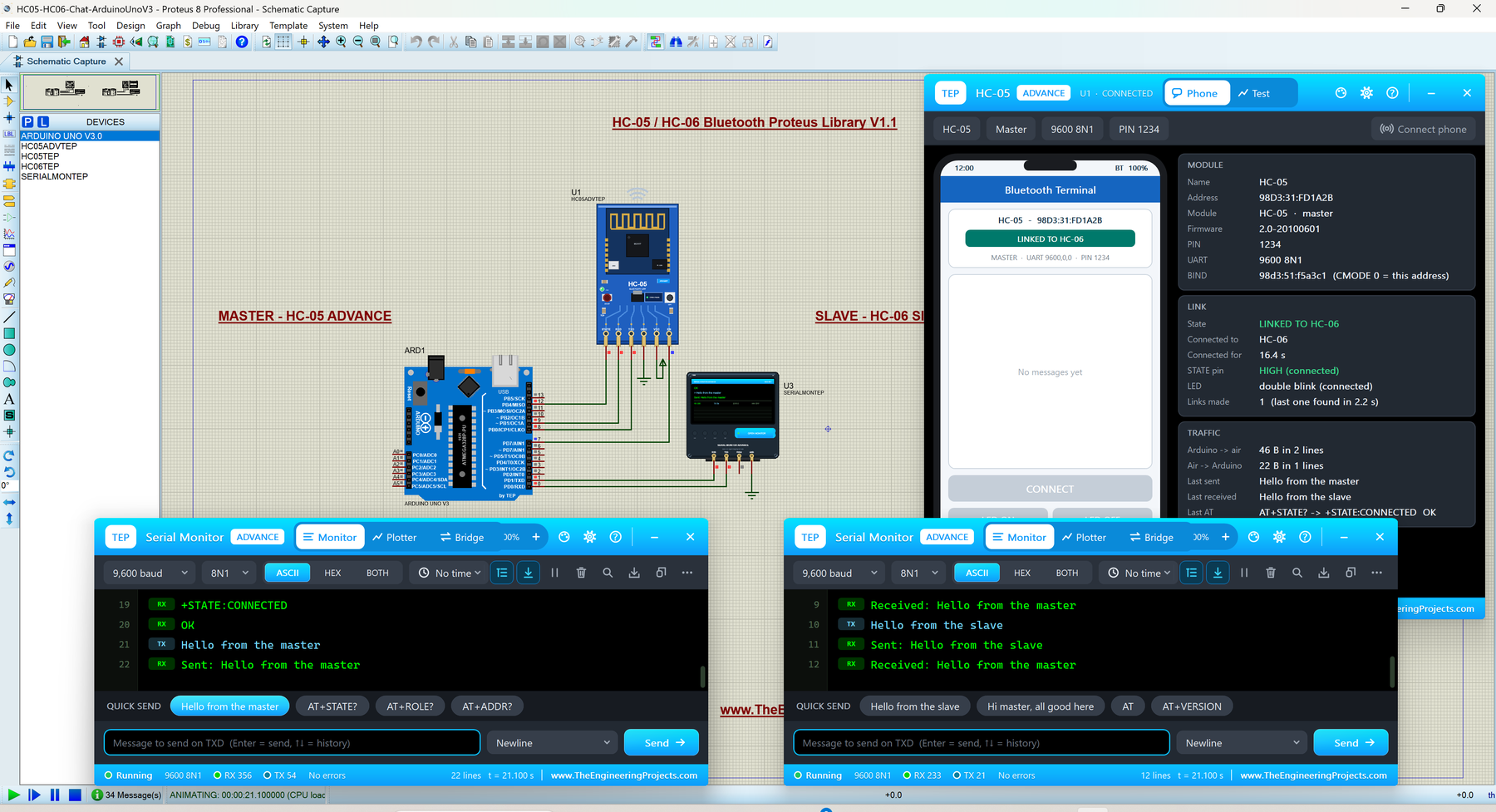
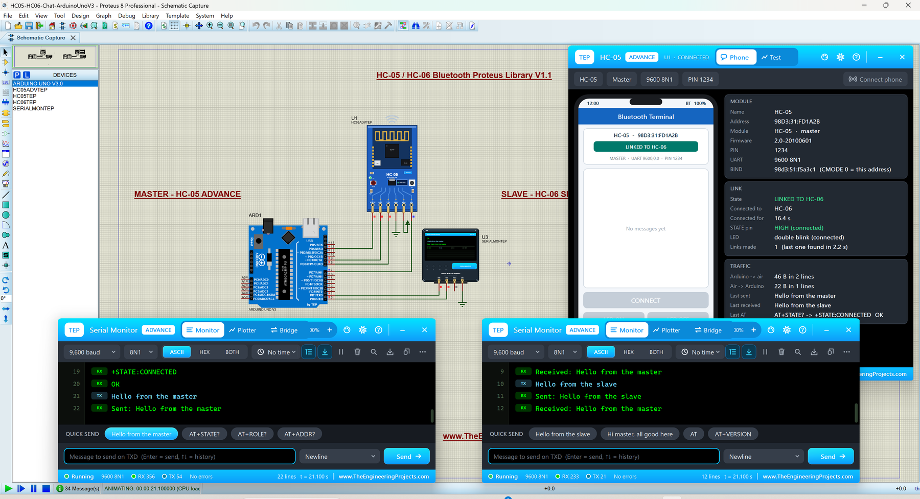
Here is the HC-05 Advance master of the chat demo, a few seconds after Run:
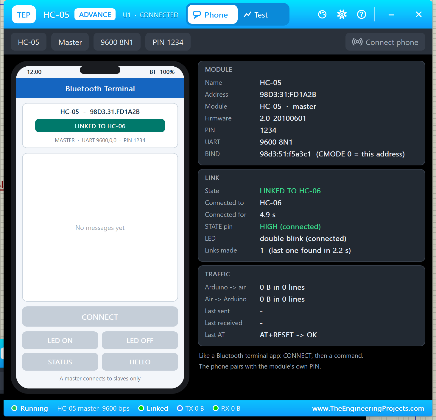
The MODULE card adds the BIND address (CMODE 0 = this address). The LINK card says LINKED TO HC-06, STATE pin HIGH, LED double blink and links made 1 (last one found in 2.2 s). The last AT, "AT+RESET -> OK", ended the sketch's set-up. The phone is grey: "A master connects to slaves only".
The Test Page
The Test page is the most powerful part of the Advance devices; everything on it is computed by the simulation. Here it is on the HC-06 before any test:
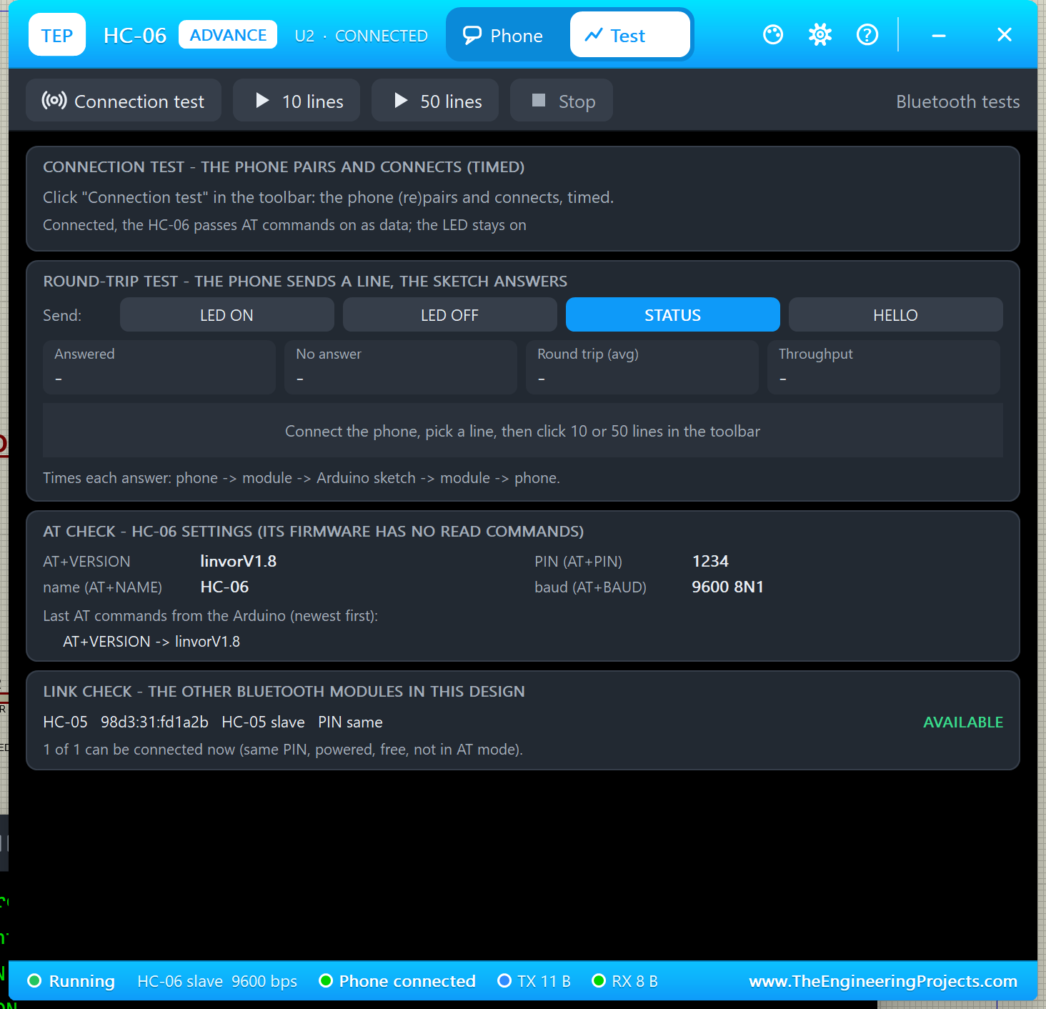
1. Connection Test
Click Connection test: the phone (re)pairs with the PIN and connects, timed. In my run: "Test 1: paired (PIN 1234) and CONNECTED in 700 ms". Otherwise it says why: WRONG PIN, MODULE IS A MASTER, MODULE IN AT MODE ... On a master, it shows the search instead: "Master: found and linked HC-06 in 2.2 s (search + 1.2 s set-up); STATE pin HIGH". Good for: checking the PIN, and that the module is free.
2. Round-Trip Test
This test checks your sketch. Pick a line (LED ON, LED OFF, STATUS or HELLO) and click 10 lines or 50 lines. The phone sends the line and times the trip: phone -> module -> Arduino sketch -> module -> phone. I picked STATUS and 10 lines:
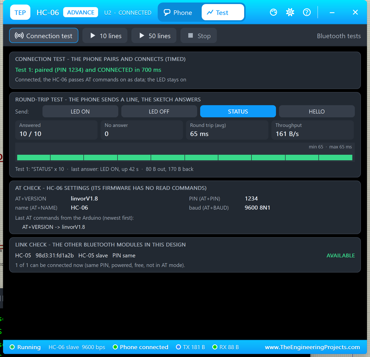
Result: Answered 10 / 10, No answer 0, round trip 65 ms, throughput 161 B/s and "last answer: LED ON, up 42 s · 80 B out, 170 B back". Good for: finding a sketch that doesn't answer, or answers slowly.
3. AT Check
The AT check shows what the AT queries would answer right now, plus the last AT commands your Arduino sent. The HC-06 firmware has no read commands, so its card lists the values (linvorV1.8, HC-06, PIN 1234, 9600 8N1). On the HC-05 master, it is much richer:
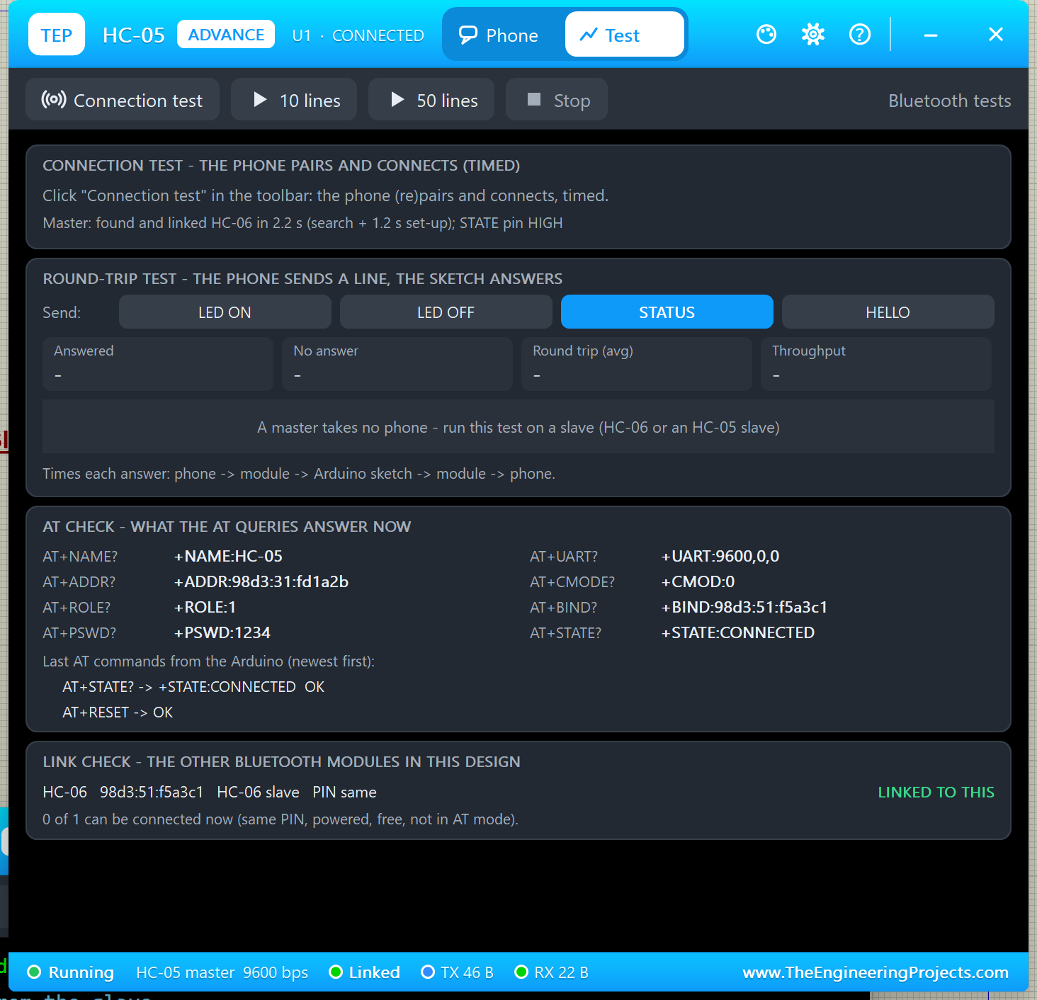
All eight queries: +NAME:HC-05, +ADDR:98d3:31:fd1a2b, +ROLE:1 (master), +PSWD:1234, +UART:9600,0,0 (9600 bps, one stop bit, no parity), +CMOD:0, +BIND:98d3:51:f5a3c1 and +STATE:CONNECTED. The last commands were "AT+STATE? -> +STATE:CONNECTED OK" and "AT+RESET -> OK". Good for: checking that your set-up sketch made the module a master bound to the right slave.
4. Link Check
The link check lists every other HC-05 / HC-06 in the design: role, PIN same or not, BIND match, and whether it can be connected now, or why not. Above, the master sees the HC-06 as LINKED TO THIS; in the LED demo, the HC-06 saw the HC-05 as AVAILABLE ("same PIN, powered, free, not in AT mode"). Good for: finding out why a master never connects.
Settings and Help
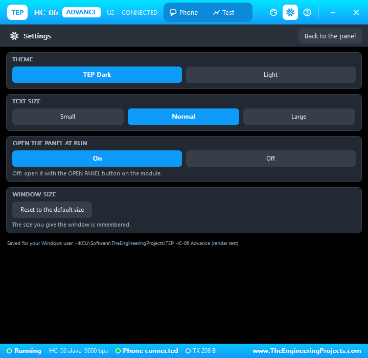
These two pages work exactly like in our HC-12 Library for Proteus, so I keep this short. The gear icon opens Settings: theme (TEP Dark or Light), text size, open the panel at Run (On / Off) and the window size, saved for your Windows user.
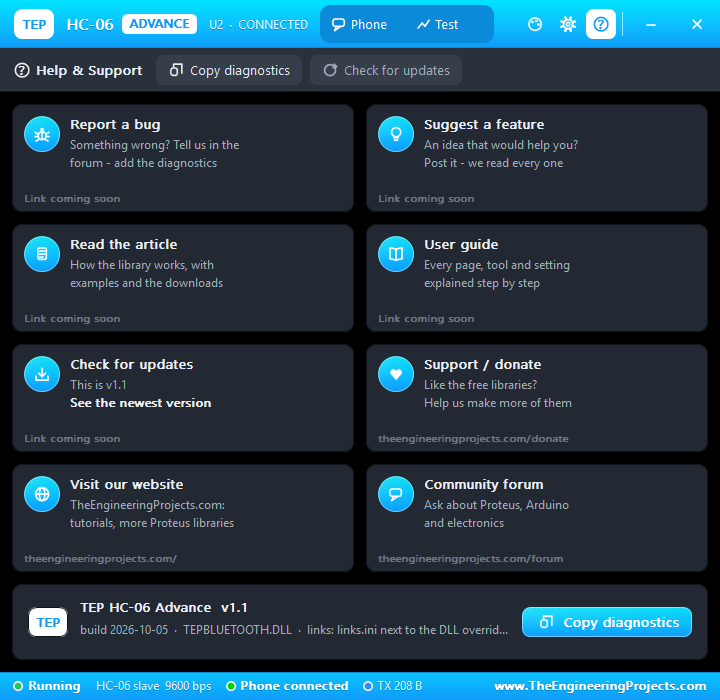
The ? icon opens Help & Support: eight cards (bug report, feature idea, article, user guide, updates, donate, website, forum) and Copy diagnostics, which copies the settings, link, counters and test results for a bug report.
HC-05 and HC-06 AT Commands Supported
HC-05 AT Commands
EN high, and CR LF after each command. All the commands of the HC-05 model:
| Command | What it does (reply) |
|---|---|
| AT | Test (OK) |
| AT+RESET | Restart; a new ROLE applies after it (OK) |
| AT+VERSION? | Firmware (+VERSION:2.0-20100601, then OK) |
| AT+ORGL | Factory settings (see the warning below) |
| AT+ADDR? | Own address (+ADDR:98d3:31:fd1a2b) |
| AT+NAME? / AT+NAME= | Read / set the name (+NAME:HC-05) |
| AT+RNAME?(address) | Name of another module |
| AT+ROLE? / AT+ROLE=0, 1 or 2 | Role: 0 slave, 1 master; 2 is accepted too (+ROLE:1) |
| AT+PSWD? / AT+PSWD= | PIN (+PSWD:1234) |
| AT+UART? / AT+UART=baud,stop,parity | Data UART (+UART:9600,0,0) |
| AT+CMODE? / AT+CMODE= | Connect mode: 0 BIND address only, 1 any slave (+CMOD:0) |
| AT+BIND? / AT+BIND= | The address a master connects to (+BIND:98d3:51:f5a3c1) |
| AT+STATE? | Current state (+STATE:CONNECTED) |
| AT+INIT, AT+INQ, AT+INQC | Start the profile, search for modules (+INQ:98d3:51:f5a3c1,1f00,7fff, then OK), stop the search |
| AT+PAIR, AT+LINK, AT+DISC | Pair with / connect to an address, disconnect |
| AT+ADCN?, AT+MRAD? | Number of paired modules, most recently used address |
| AT+CLASS, AT+IAC, AT+INQM | Accepted |
| Unknown command | ERROR:(0) |
Careful with AT+ORGL: it restores the factory settings, which sets the data UART to 38400 and the name to H-C-2010-06-01. Many people think their module "stopped working" after it; it just talks at a different speed now.
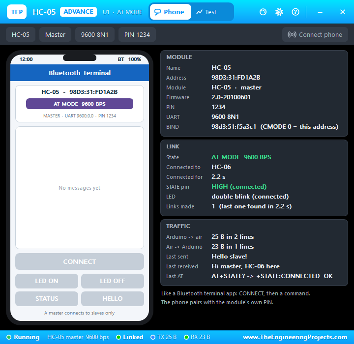
In mini AT mode, the HC-05 master shows AT MODE 9600 BPS in purple, while STATE stays HIGH and the link stays up:
HC-06 AT Commands (linvor Firmware)
Only while nothing is connected, and with no line ending: a short pause ends the command, and the reply (without CR LF) comes about 0.2 s later:
| Command | Reply | What it does |
|---|---|---|
| AT | OK | Test |
| AT+VERSION | linvorV1.8 | Firmware version |
| AT+NAMExxx | OKsetname | Sets the name |
| AT+PINxxxx | OKsetPIN | Sets the PIN |
| AT+BAUDn | OK9600 (for n = 4) | Speed: 1 = 1200 ... 4 = 9600 ... 8 = 115200 ... C = 1382400; applies after the reply |
| AT+PN / AT+PE / AT+PO | OK None / OK EVEN / OK ODD | Parity none / even / odd |
| Anything else | (no reply) |
HC-05 Master and Slave Pairing Explained
Two modules can only talk when one of them is a master: the master searches and connects, the slave waits. A phone can only connect to a slave, and an HC-06 is always a slave, so to link two Arduinos you need an HC-05 as the master. You set it up with four AT commands:
- ROLE:
AT+ROLE=1makes the HC-05 a master (0 = slave). It applies afterAT+RESET. - CMODE:
AT+CMODE=0means "connect only to the BIND address";AT+CMODE=1means "connect to any slave". - BIND:
AT+BIND=98d3,51,f5a3c1is the slave's address. You find it withAT+ADDR?on an HC-05 slave, withAT+INQon the master, or in the BTADDR property in Proteus. - PIN: both modules need the same PIN:
AT+PSWD=on the HC-05,AT+PINon the HC-06 (1234 by default).
After AT+RESET, the master searches every second and connects to its slave; the link set-up takes 1.2 s, and in my run the master was linked 2.2 s after it started searching. STATE goes high, and the master reconnects by itself if the link is lost. The slave's phone then says LINKED TO HC-05, with grey buttons, because the module is busy:
Tip: the address is shown with colons (98d3:51:f5a3c1), but AT+BIND takes it with commas: AT+BIND=98d3,51,f5a3c1.
Arduino HC-05 Proteus Demo 1: LED Control from the Phone
Now let's run the first demo. The project HC05-HC06-LED-Control-ArduinoUnoV3.pdsprj has two Arduino UNOs from our Arduino Library for Proteus V3.0, each with an LED and a 220 Ω resistor on A0. UNO 1 has the HC-05 Simple (U1, phone on the sheet) and Serial Monitor U3; UNO 2 has the HC-06 Advance (U2, phone in the pop-up) and Serial Monitor U4.
Wiring
| From | To | Why |
|---|---|---|
| HC-05 / HC-06 TXD | Arduino D8 | AltSoftSerial RX |
| HC-05 / HC-06 RXD | Arduino D9 | AltSoftSerial TX |
| HC-05 STATE | Arduino D12 | HIGH while a phone is connected |
| HC-05 / HC-06 VCC / GND | +5 V / ground | Power |
| LED + 220 Ω | A0 to GND | The LED the phone switches |
| Serial Monitor RXD | Arduino D1 (TX) | Shows what the Arduino prints |
| Serial Monitor TXD | Arduino D0 (RX) | Sends what you type |
| Serial Monitor GND | Ground | RXD2 stays open |
Want to know more about these pins? Read our Introduction to Arduino UNO.
Why AltSoftSerial and Not SoftwareSerial?
Most HC-05 examples use SoftwareSerial. It sends fine in Proteus 8.5 but cannot receive: it needs pin-change interrupts, which the Proteus 8.5 ATmega328P model never runs. AltSoftSerial (Paul Stoffregen, MIT licence) uses Timer1 instead and works in Proteus and on real boards, always on D8 (RX) and D9 (TX) of the UNO.
One more rule: keep D10 free. Reading or writing D10 changes a Timer1 register that AltSoftSerial uses for every bit it sends. When STATE was on D10, "LED is ON" arrived as "LEDZ9"! That is why STATE goes to D12, and it happens on real boards too.
The Arduino Code
The HC-05 sketch HC05_LED_Control.ino creates the Bluetooth port and the pins:
AltSoftSerial BT;                      // RX = D8 (from HC-05 TXD), TX = D9 (to HC-05 RXD)
const byte LED_PIN = A0;
const byte STATE_PIN = 12;             // HC-05 STATE: HIGH while a phone is connected (not D10: see above)
Every line from the phone goes to handle(), which switches the LED and answers through the module:
  if (!strcmp(command, "LED ON")) {
    digitalWrite(LED_PIN, HIGH);
    BT.println(F("LED is ON"));
    Serial.println(F("  -> LED is ON"));
  } else if (!strcmp(command, "LED OFF")) {
The HC-06 sketch is the same, but it first asks the module for its firmware, with no line ending and a pause for the answer:
  BT.print(F("AT+VERSION"));           // no line ending for an HC-06
  delay(1000);                         // the HC-06 answers after a pause
  Serial.print(F("HC-06 firmware: "));
  while (BT.available()) Serial.write(BT.read());
If you change a sketch, compile it and load the new HEX file into the UNO; see How to get the HEX file from Arduino. New to Arduino? Start with our Arduino Tutorial for Beginners.
How to Run Demo 1
- Open
Proteus Simulation\HC05-HC06-LED-Control-ArduinoUnoV3.pdsprj(keep the .hex files and both DLLs beside it). - Press Run. Both Serial Monitors open at 9600 baud, and so does U2's pop-up. U4 shows "HC-06 firmware: linvorV1.8".
- On U1's phone, click CONNECT, then LED ON. Try LED OFF, STATUS and HELLO, and watch the antenna glow and the waves.
- In U2's pop-up, click CONNECT and the commands, then try the tests on the Test tab.
Simulation Results
After LED ON from the pop-up phone, U4 (HC-06) shows:
HC-06 firmware: linvorV1.8
HC-06 LED control - connect from the phone, then send LED ON / LED OFF / STATUS / HELLO
Phone: LED ON
  -> LED is ON
U3 (HC-05) shows the same exchange, with "Phone connected" after CONNECT. STATUS answers like "LED ON, up 12 s" (seconds since Run), and HELLO answers "Hello from Arduino!".
Arduino HC-05 Proteus Demo 2: Master / Slave Chat
The second project, HC05-HC06-Chat-ArduinoUnoV3.pdsprj, links two UNOs without any phone. UNO 1 has the HC-05 Advance (U1, the master) and monitor U3; UNO 2 has the HC-06 Simple (U2, the slave) and monitor U4. You saw it running in the first image of this article.
Wiring
The same as demo 1 without the LEDs, but now the sketch uses the HC-05's EN pin on D7 to switch AT mode. STATE stays on D12, and the HC-06 uses only TXD (D8) and RXD (D9).
The Arduino Code
The master sketch HC05_Master_Chat.ino knows the slave's address:
const char SLAVE_ADDRESS[] = "98d3,51,f5a3c1"; // the HC-06's address (AT+ADDR? on the slave; Proteus: its BTADDR property)In setup(), it pulls EN high and turns the HC-05 into a master bound to that address:
  digitalWrite(EN_PIN, HIGH);          // AT mode at 9600
  delay(100);
  Serial.println(F("HC-05 master set-up:"));
  command(F("AT"));
  command(F("AT+ROLE=1"));             // master
  command(F("AT+CMODE=0"));            // connect only to the BIND address
  command(F("AT+BIND="), SLAVE_ADDRESS);
  command(F("AT+RESET"));              // the new role applies after a restart
  digitalWrite(EN_PIN, LOW);           // restart in data mode
In loop(), a typed line that starts with AT goes to the master's own HC-05 in mini AT mode; any other line goes over the air:
    if (line[0] == 'A' && line[1] == 'T') {
      Serial.print(F("Command: "));
      Serial.println(line);
      digitalWrite(EN_PIN, HIGH);      // mini AT mode at the data speed
      delay(50);
      sendCommand(line);
      digitalWrite(EN_PIN, LOW);       // back to data mode
      delay(50);
    } else {
      BT.print(line);
      BT.print(F("\r\n"));
      Serial.print(F("Sent: "));
      Serial.println(line);
    }
How to Run Demo 2
- Open
Proteus Simulation\HC05-HC06-Chat-ArduinoUnoV3.pdsprjand press Run. - Wait a few seconds until U3 prints "Connected - ..." and U2's phone says LINKED TO HC-05.
- In U3, click Hello from the master (or type a line and press Enter). Answer from U4 with Hello from the slave or Hi master, all good here.
- In U3, click AT+STATE?, AT+ROLE? or AT+ADDR? to ask the master's own HC-05.
Simulation Results
At start-up, U3 shows the master set-up (every reply OK) and then the link:
HC-05 master set-up:
> AT
OK
> AT+ROLE=1
OK
> AT+CMODE=0
OK
> AT+BIND=98d3,51,f5a3c1
OK
> AT+RESET
OK
Searching for the slave...
Connected - type a line and press Enter (lines starting with AT go to this HC-05)
At the same time, the slave sketch HC06_Slave_Chat.ino checks its HC-06 and sets the same PIN before the master connects. U4 shows:
HC-06 slave:
> AT
  OK
> AT+VERSION
  linvorV1.8
> AT+PIN1234
  OKsetPIN
Waiting for the master - then type a line and press Enter
Then the chat. In my run, U3 asked AT+STATE? and sent a hello:
Command: AT+STATE?
+STATE:CONNECTED
OK
Sent: Hello from the master
and U4 shows the other side:
Received: Hello from the master
Sent: Hello from the slave
Received: Hello from the master
The link stays up during AT+STATE?. On U4, the quick buttons AT and AT+VERSION are answered by the HC-06 only while no master is connected; once linked, they travel to the master as text. That is exactly how the real HC-06 works.
The TEP Serial Monitor in the Demos
Each Arduino has its own TEP Serial Monitor Advance (U3 for UNO 1, U4 for UNO 2) at 9600 baud. It opens at Run and, in the chat demo, has the quick-send buttons. Closed one? Click OPEN MONITOR on its symbol. Read all about it in TEP Serial Monitor Advance for Proteus.
Troubleshooting
WRONG PIN, or the Master Never Connects
The PINs differ, BIND does not match the slave's address (or use AT+CMODE=1), or the slave is connected to a phone. The Advance link check tells you which.
The Arduino Prints Nothing, or Garbage
Nothing: your sketch uses SoftwareSerial; use AltSoftSerial, the hardware Serial port or an Arduino Mega. Garbage: something reads or writes D10 while AltSoftSerial runs.
No Reply to HC-05 AT Commands
Use 38400 if EN was high at power-up, the data speed in mini AT mode, and CR LF after each command.
The Round-Trip Test Says "No answer"
The phone must be connected, and your sketch must answer the line (the LED sketches answer all four).
No Phone, No Pop-Up or No Monitor
TEPBLUETOOTH.DLL or TEPSERIALMON.DLL is missing from MODELS and the project folder. For the Advance, click OPEN PANEL or turn "Open the panel at Run" back on.
Duplicate Parts, or the Red X Does Not Close the Phone
The v1.0 library is still installed, or your design holds the v1.0 symbol. Delete TEPHC05.LIB, TEPHC06.LIB and their .IDX files in LIBRARY, and pick the part again.
Things to Know Before Using a Real HC-05 or HC-06
- Power: VCC is 3.6 - 6 V on the usual breakout.
- 3.3 V logic on RXD: the module's RXD is a 3.3 V input. Use a 1 k / 2 k divider from the Arduino's 5 V TX: 1 k from D9 to RXD, and 2 k from RXD to GND.
- D10: keep it free while AltSoftSerial runs; this is a real-hardware issue too.
- Firmware: modules from different makers differ; HC-05 modules with firmware 3.0 may answer some commands differently.
Limitations of the Simulation
- The radio itself is not modelled: no range and no interference. Every module in a design can reach every other one.
- No BLE, no Bluetooth profiles other than serial, no HID or other firmwares, and no supply current.
- Bytes take about 20 ms to cross the Bluetooth link.
- Tested in Proteus 8.5 (both demos and the Proteus screenshots in this article) and with 459 automatic checks on the PC; Proteus 7 is not supported.
Need more range than Bluetooth? Try our HC-12 Library for Proteus or our nRF24L01 PA LNA Library for Proteus.
So, that was all about the HC-05 & HC-06 Bluetooth Library for Proteus V1.1. I hope the virtual phone, the four devices and the test tools make Bluetooth projects much easier to understand. Please share your feedback in the comments or in our forum, and if you have any questions, ask in the comments and I will help you out. Till the next tutorial, take care and have fun!