Hello friends, I hope you all are doing great. Today, I am going to share the new MH-Z19B CO2 Sensor Library for Proteus V1.0. The MH-Z19B is the small gold-plated NDIR (infrared) carbon dioxide sensor that sits in many indoor air-quality monitors, ventilation controllers and school CO2 traffic lights. It measures real CO2, not just "bad air", and it talks to an Arduino over a UART and a PWM pin.
Behind the part sits our own model, written from Winsen's user's manual and checked against the MH-Z19 Arduino library, the one most makers use with this sensor - so the library's own commands get the answers they expect. The sensor preheats, follows a change of the air with its response time, holds its zero point at 400 ppm, corrects itself with ABC, and can be calibrated right or wrong, just like the real one. You get a Simple device with a live STATUS panel and an Advance device with a pop-up window and three test tools. The demo runs on our Arduino UNO V4.0.
NOTICE: a CO2 sensor is easy to fake: a number that follows a slider. We wanted more. Our MH-Z19B answers the same 9-byte commands as the real one, bit by bit, gives the same PWM cycle, needs its preheat, lags behind the air and can be calibrated in the wrong air - so a sketch that reads too early, uses the wrong range or calibrates in a stuffy room fails exactly as it does with a real sensor. It took our team a lot of hard work. Your feedback is the fuel that keeps us going, so please tell us what you think in the comments below or in the MH-Z19B board of our forum. And if our free libraries help you, you can buy us a coffee. So, let's get started with the MH-Z19B CO2 Sensor Library for Proteus V1.0:
What is the MH-Z19B CO2 Sensor?
The MH-Z19B is a non-dispersive infrared (NDIR) sensor. A small lamp shines through a gold-plated chamber onto a detector behind a filter that passes only the wavelength CO2 absorbs. The more CO2 in the chamber, the less light arrives; the sensor turns that into ppm (parts per million) and corrects it for the temperature. Air gets in through the white diffusion window on one end. Unlike the heated metal-oxide sensors of our MQ Gas Sensor Library for Proteus, our Gas Sensor Library for Proteus V2.0 (the MQ-2) or the MQ-135 air quality sensor, it sees CO2 and nothing else.
| Parameter | MH-Z19B (the manual, V1.5) |
|---|---|
| Gas | CO2 |
| Range | 0 - 2000, 0 - 5000 or 0 - 10000 ppm (set by a command) |
| Accuracy | 50 ppm + 5 % of the reading |
| Supply | 4.5 to 5.5 V; under 20 mA on average, 150 mA peaks |
| Signals | 3.3 V (compatible with 5 V) |
| Outputs | UART (9600 baud), PWM, analog Vo (0.4 - 2 V) |
| Preheat | 3 minutes |
| Response time | T90 under 120 s |
| Zero point | 400 ppm (hand-operated by HD, by a command, or automatic - ABC) |
Fresh Air is 400 ppm
Outdoor air has about 400 to 420 ppm of CO2. Indoors we breathe it out, so a closed room climbs to 1000, 2000 ppm and more - a common sign that it needs fresh air. That is why the MH-Z19B calls 400 ppm its zero point: a zero calibration does not mean "no CO2" but "this air is fresh outdoor air". Get that wrong and every reading after it is wrong.
What's New in MH-Z19B CO2 Sensor Library for Proteus V1.0
- The real protocol: 9-byte commands at 9600 baud with the checksum - 0x86 (read), 0x87 (zero), 0x88 (span), 0x79 (ABC) and 0x99 (range) from the manual, plus 0x85, 0x84, 0x7D, 0x9B, 0x9C, 0xA0, 0xA2, 0xA3 and 0x78 that the MH-Z19 library uses. A wrong checksum gets no answer.
- Two kinds of reading: 0x86 and the PWM pin stay between 400 ppm and the range; 0x85 does not, so it shows a bad calibration below 400 and the CO2 above the range.
- PWM: the manual's 1004 ms cycle, HIGH for 2 ms + 1000 ms x CO2 / range.
- HD: held LOW for 7 seconds, the pin calibrates the zero point.
- The behaviour of a real sensor: the preheat, the response time (T90), a zero drift, automatic baseline correction (ABC) and zero and span calibrations that can go wrong.
- The air on the panel: its CO2 (- / + and a ruler), five presets, BREATHE, VENTILATE, DRIFT +150 and A DAY (ABC).
- Three test tools on the Advance device: UART & commands, PWM & HD, and Calibration & ABC.
- A two-node demo on our Arduino UNO V4.0 with the MH-Z19 library: the UART and the PWM pin read side by side, and the CAL, ABC, RANGE, HD and STATUS commands.
- A compact package: about 1.26 MB, without the C++ source code of the model.
Two Devices: Simple and Advance
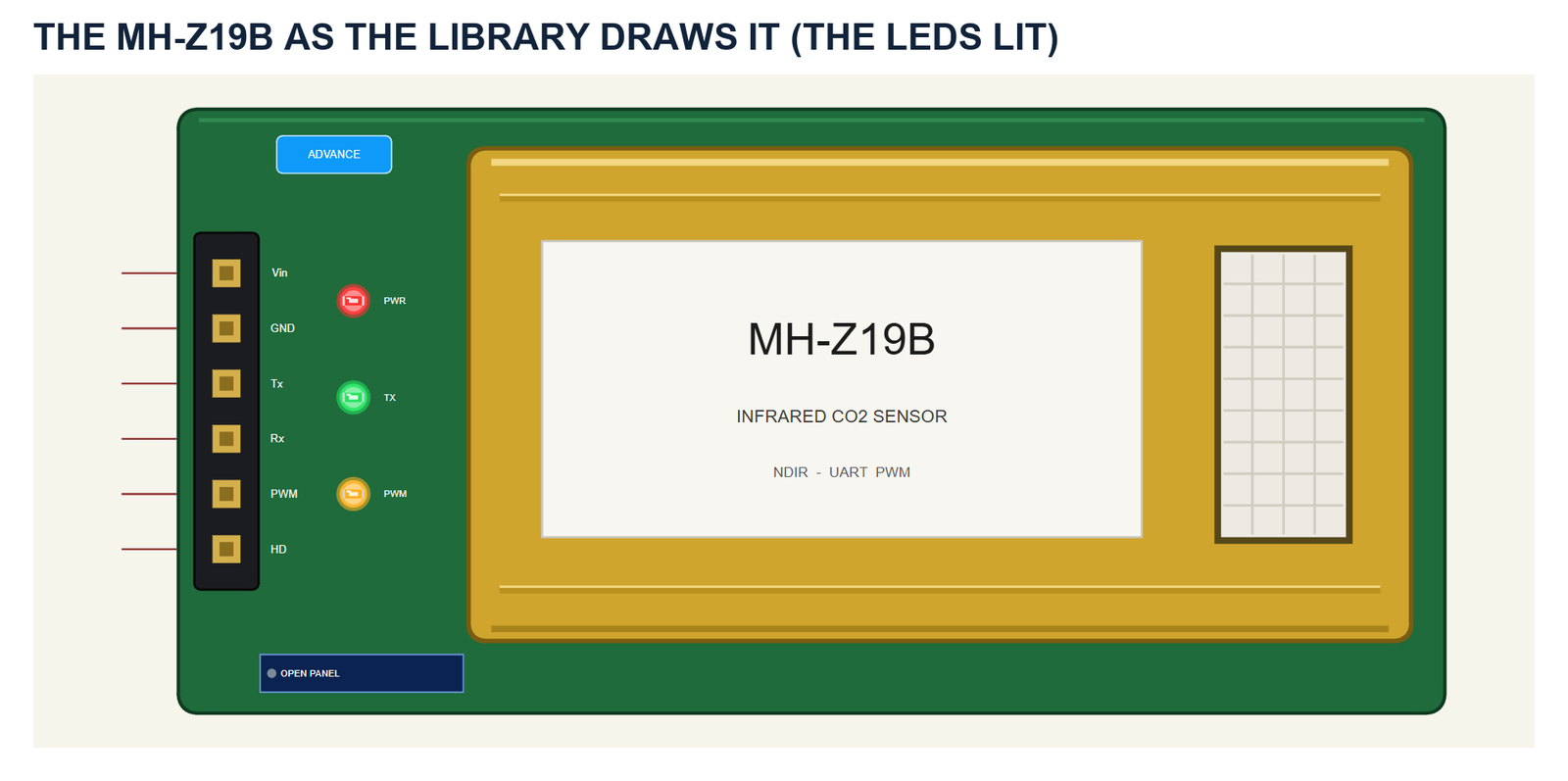
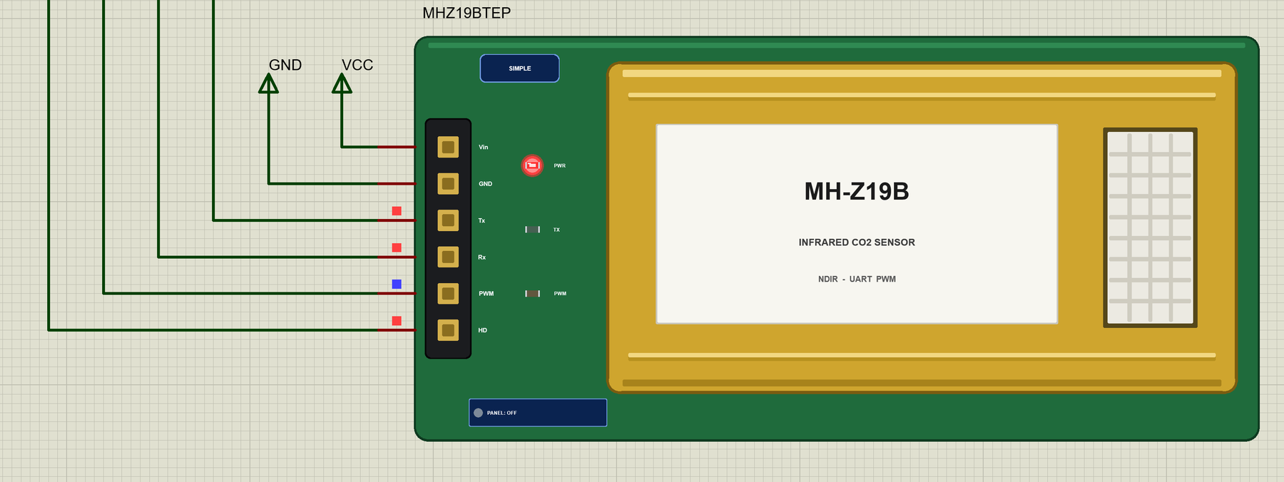
The part shows the sensor from above: the gold-plated chamber with its label and the white diffusion window, on a green board with the pins on the left - Vin, GND, Tx, Rx, PWM and HD. The real sensor has one more pin, the analog Vo; the model does not drive it, so the part leaves it out. The board carries three LEDs: PWR while it has power, TX with every answer, and PWM, which follows the PWM pin - the more CO2, the longer it stays on in each second. The sensor is drawn at about three times its real size.
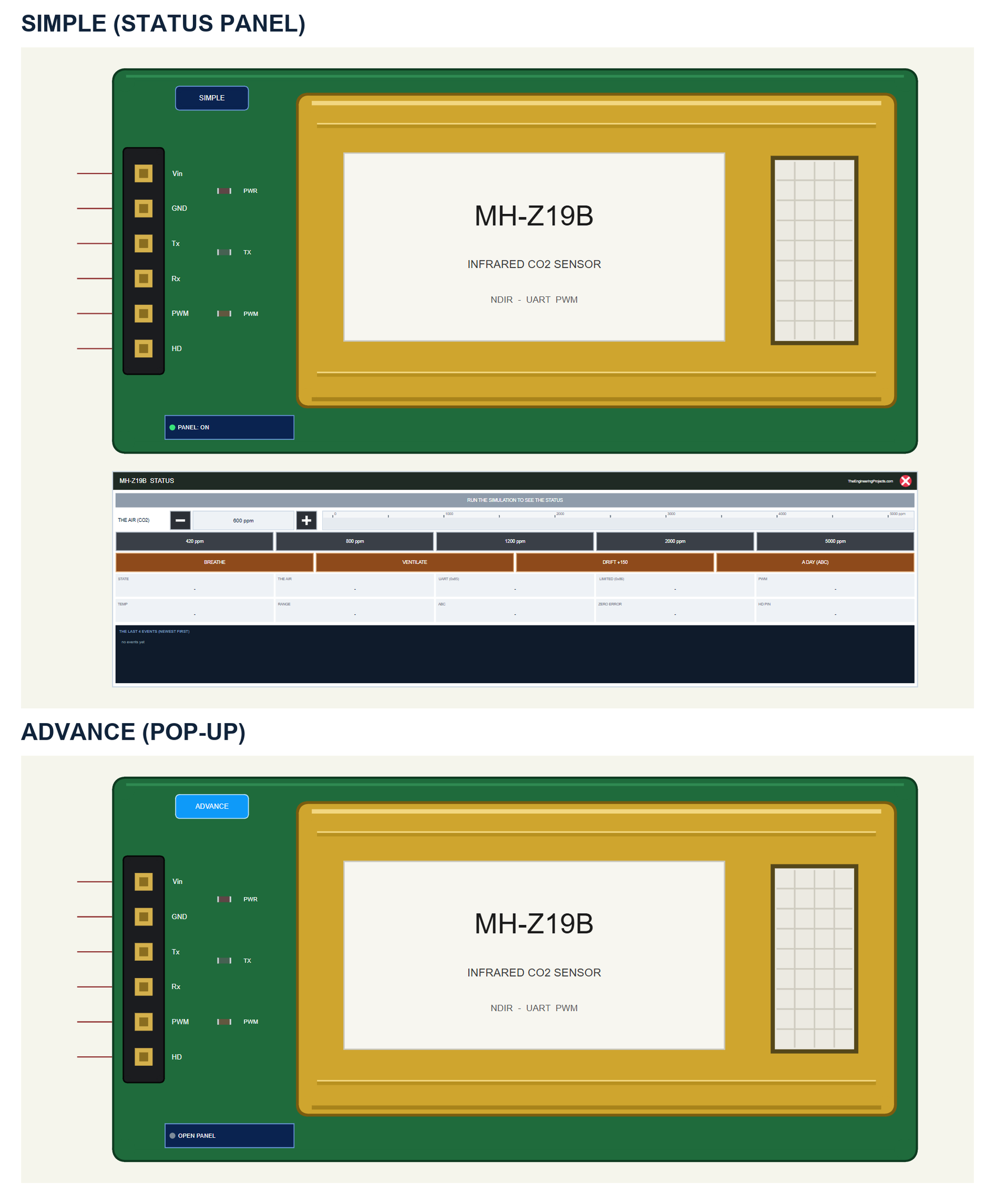
| Simple | Advance | |
|---|---|---|
| Device | MHZ19BTEP | MHZ19BADVTEP |
| On the schematic | The sensor and the STATUS panel | The sensor |
| The air and the actions | On the STATUS panel | In the pop-up |
| Status | Banner, a ruler, 10 readouts, the last 4 events | A pop-up: Sensor, Event log, Tests |
Download MH-Z19B CO2 Sensor Library for Proteus
Click the button below to download MH-Z19B-CO2-Sensor-Library-for-Proteus-v1.0.zip (about 1.26 MB, without the C++ source code of the model):
MH-Z19B CO2 Sensor Library for Proteus V1.0- README.txt: the devices, installation, the demo, wiring, the test tools and real hardware.
- Proteus Library Files:
TEPMHZ19B.LIBandArduinoV4TEP.LIBfrom our Arduino Library for Proteus V4.0. - Proteus Model Files:
TEPMHZ19B.DLLandTEPARDUINO.DLL. - Proteus Simulation:
MH-Z19B-CO2-ArduinoUnoV4.pdsprj,MHZ19B_CO2_Demo.hexand copies of the two DLLs. - Arduino Code:
MHZ19B_CO2_Demo.ino- it needs the MH-Z19 and AltSoftSerial libraries from the Library Manager to rebuild it.
No Proteus yet? Read How to Download and Install Proteus 7 and 8. New to libraries? Follow How to Install a New Library in Proteus.
How to Install MH-Z19B CO2 Sensor Library for Proteus
- Close Proteus and extract the whole zip file, for example to your Desktop.
- Copy the two files from Proteus Library Files into the LIBRARY folder of Proteus (usually
C:\Program Files (x86)\Labcenter Electronics\Proteus 8 Professional\LIBRARY). - Copy
TEPMHZ19B.DLLandTEPARDUINO.DLLfrom Proteus Model Files into the MODELS folder. - Delete
TEPMHZ19B.IDXfrom the LIBRARY folder if it is there. - Start Proteus, press P and search for MHZ19 (or CO2).
Tip: keep the Proteus Simulation folder together, because the project needs its .hex file and the DLLs beside it. The library is tested in Proteus 8.5; Proteus 7 is not supported.
The MH-Z19B Part in Proteus
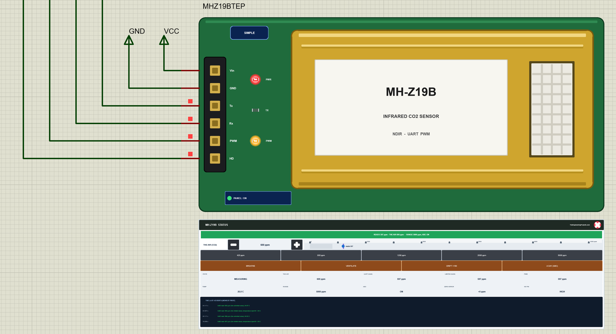
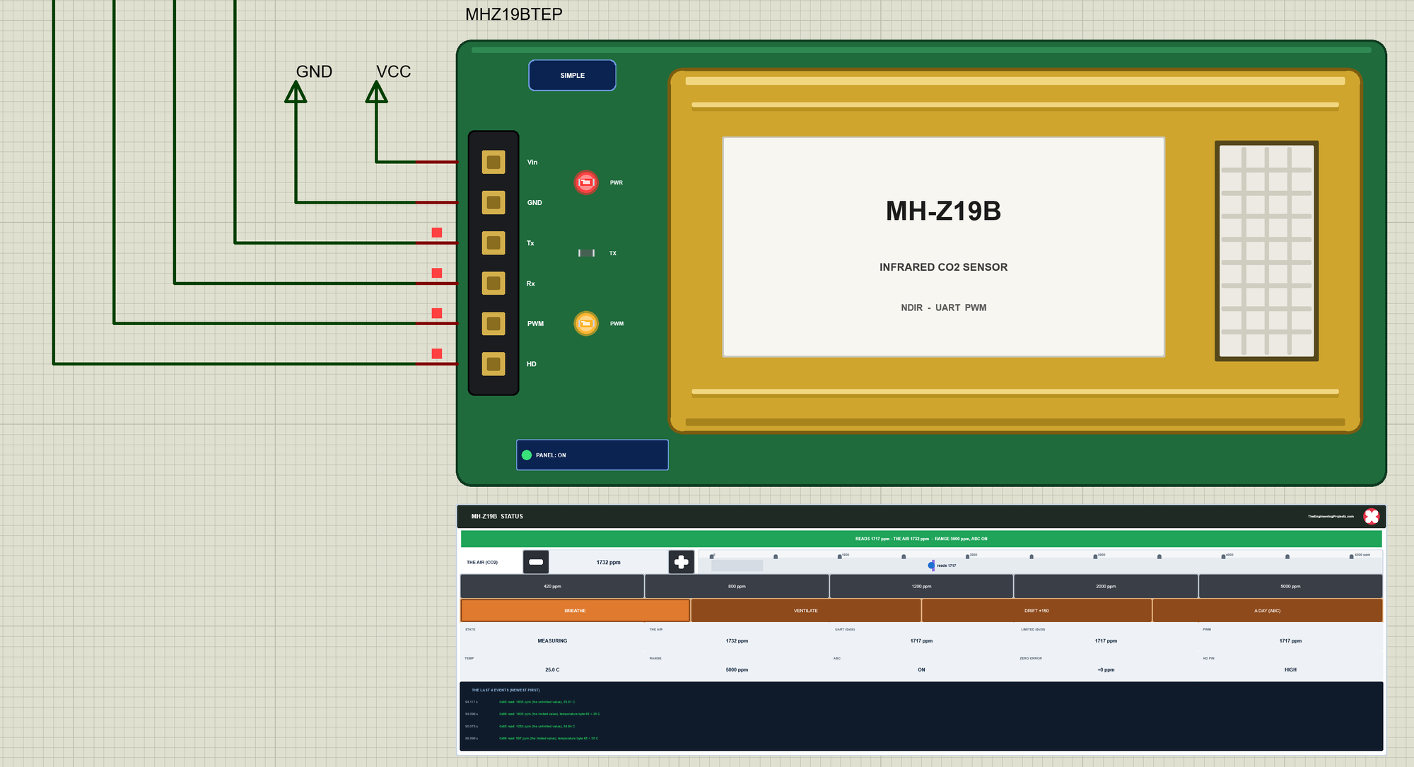
The Simple device adds the STATUS panel. Its banner compares the reading with the air: green when they agree, amber during the preheat, while the sensor still follows a change, or above the range, and red for a zero error or a changed gain. Below it are THE AIR (CO2) with - and + (50 ppm a click) and a ruler from 0 to 5000 ppm with the air (the violet line) and the reading (the blue dot); five presets - 420, 800, 1200, 2000 and 5000 ppm; and four actions - BREATHE, VENTILATE, DRIFT +150 and A DAY (ABC). Ten readouts follow - the state, the air, the 0x85 and 0x86 values, PWM, the temperature, the range, ABC, the zero error and the HD pin - and the last four events. The badge, the LEDs, the button and the panels are TEP additions.
The red X closes the STATUS panel, and the PANEL button on the board opens it again:
The Advance device keeps the schematic clean: only the sensor. The live data opens in a pop-up window at Run, and the OPEN PANEL button on the board brings the window back:
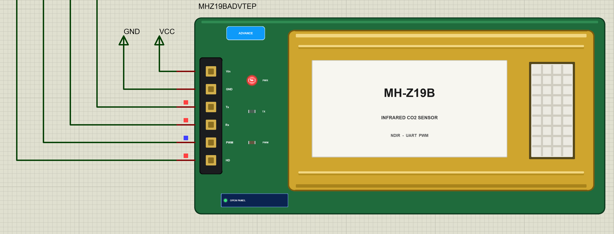
The properties set the start: CO2 (the air, 600 ppm), RANGE (5000 ppm), ABC (ON), PREHEAT (180 s, the manual's 3 minutes), T90 (60 s; the manual says under 120 s) and TEMP (25 C).
The Demo Circuit
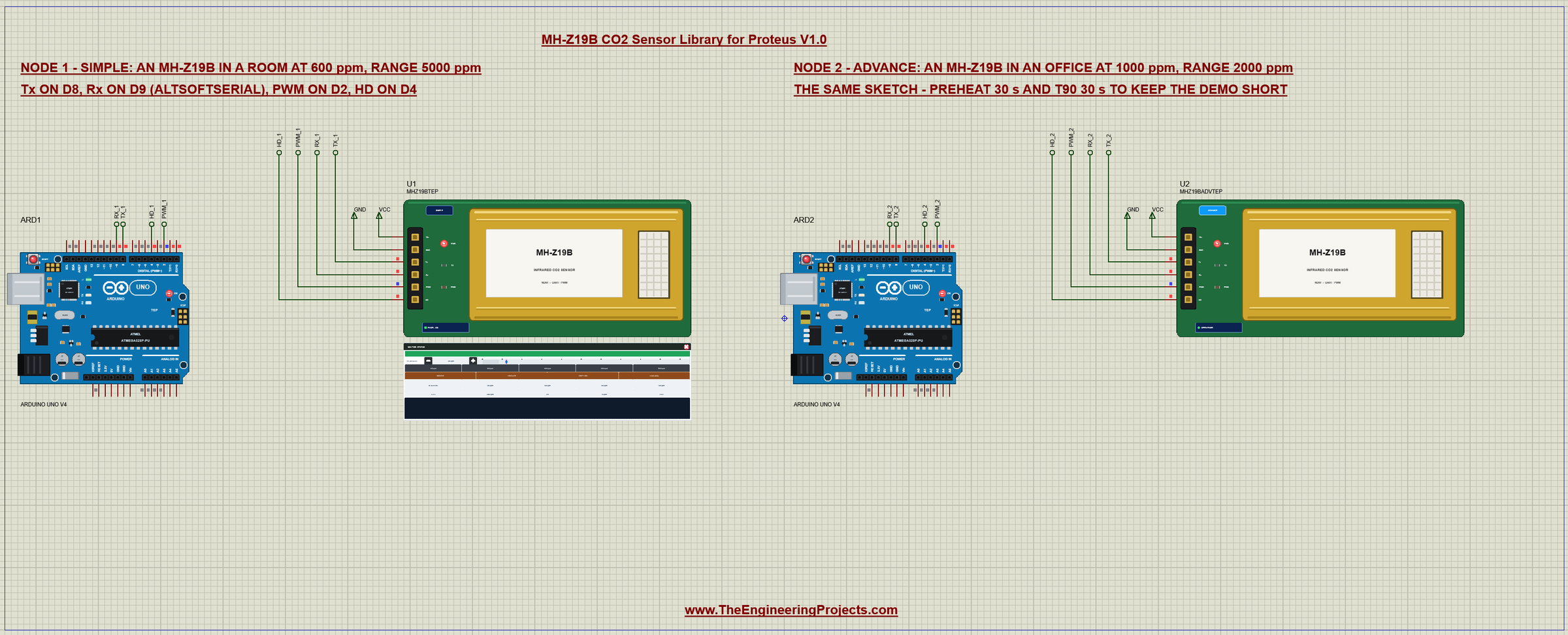
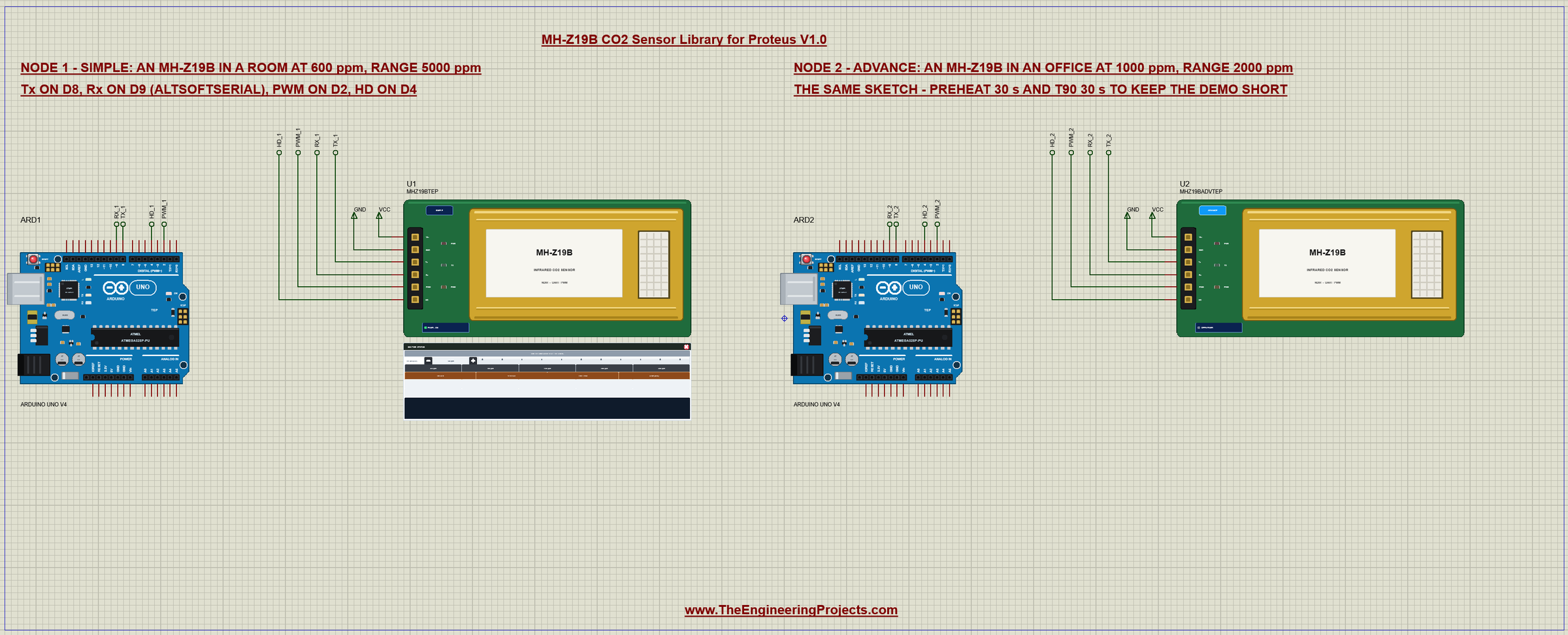
The demo project has two nodes, each an Arduino UNO V4.0 from our Arduino UNO Library for Proteus V4.0 with an MH-Z19B. Node 1 is a room at 600 ppm with the range at 5000 ppm; node 2 an office at 1000 ppm with the range at 2000 ppm. Both sensors have PREHEAT and T90 set to 30 s to keep the demo short, and both UNOs run the same MHZ19B_CO2_Demo.hex.
Wiring
| MH-Z19B | Arduino UNO |
|---|---|
| Vin | 5V (150 mA peaks for the lamp) |
| GND | GND |
| Tx | D8 (AltSoftSerial RX) |
| Rx | D9 (AltSoftSerial TX) |
| PWM | D2 (INT0 - both edges timed) |
| HD | D4 (HIGH; LOW for 8 s with the HD command) |
An UNO has one hardware serial port, and it is busy with the serial monitor. SoftwareSerial cannot receive in Proteus, so the sketch uses AltSoftSerial, which always uses D8 and D9 - like our TF-Luna LiDAR Library for Proteus. More on serial ports in Arduino serial communication and how to use Arduino Software Serial. In Proteus the pins reach their UNO through net labels - TX_1, RX_1, PWM_1 and HD_1 for node 1, the same with _2 for node 2 - and Vin and GND are power terminals. The serial monitor needs no wires at all, because it is built into the UNO V4.0.
The Arduino Code
The demo sketch uses the MH-Z19 library and AltSoftSerial. New to Arduino? Start with Arduino Tutorial for Beginners and Introduction to Arduino UNO. The libraries, the pins and the serial port:
#include <AltSoftSerial.h>
#include <MHZ19.h>
const byte PWM_PIN = 2; // the sensor's PWM output (INT0)
const byte HD_PIN = 4; // the sensor's HD input: LOW for over 7 s calibrates the zero point
const unsigned long READ_EVERY = 2000; // msAltSoftSerial co2Serial; // RX D8 = the sensor's Tx, TX D9 = the sensor's Rx
MHZ19 mhz;Reading the PWM Pin
The PWM pin is read with an interrupt on D2 that fires on both edges and times them with micros() - pulseIn would block the sketch for up to a second. A rising edge ends a cycle, so its LOW time is complete:
void pwmEdge() {
  const unsigned long now = micros();
  if (digitalRead(PWM_PIN) == HIGH) {      // a new cycle: the LOW time of the last one is complete
    if (fallUs) { lowUs = now - fallUs; pwmFresh = true; }
    riseUs = now;
  } else {
    if (riseUs) highUs = now - riseUs;
    fallUs = now;
  }
}
Then the manual's formula, Cppm = range x (TH - 2 ms) / (TH + TL - 4 ms), in microseconds. The sketch reads the range from the sensor, because the formula needs the same one. More on PWM in Arduino PWM pins:
long pwmPpm() {
  noInterrupts();
  const unsigned long th = highUs, tl = lowUs;
  const bool fresh = pwmFresh;
  interrupts();
  if (!fresh || th + tl < 8000UL) return -1;
  return lround(range * (th - 2000.0) / (th + tl - 4000.0));
}
Setup and a Reading
In setup() HD is set HIGH before the pin becomes an output - the other way round it would be LOW for an instant. begin() checks the link: it asks 0x85, then 0xA2 (the last answer again) and compares the two, then 0xA0:
  Serial.println(F("TEP MH-Z19B CO2 sensor - demo V1.0"));
  digitalWrite(HD_PIN, HIGH);              // HIGH first: no LOW glitch on HD when the pin becomes an output
  pinMode(HD_PIN, OUTPUT);
  pinMode(PWM_PIN, INPUT);
  attachInterrupt(digitalPinToInterrupt(PWM_PIN), pwmEdge, CHANGE);
  co2Serial.begin(9600);
  mhz.begin(co2Serial);                    // checks the link: 0x85, then 0xA2 (the last answer), then 0xA0
Every 2 seconds the sketch asks both kinds of reading and the temperature. getCO2() is the library's default, 0x85; getCO2(false) is the manual's 0x86:
  const int co2 = mhz.getCO2();            // 0x85: the "unlimited" value (the library's default)
  const byte err = mhz.errorCode;
  const int limited = mhz.getCO2(false);   // 0x86: the datasheet's command
  const float temp = mhz.getTemperature();
During the preheat 0x86 gives 410 ppm while 0x85 is still settling higher - the test the library's own filter uses. The sketch marks those lines:
else if (limited == 410 && co2 - limited >= 10) Serial.print(F(" - preheating"));The Commands
CAL sends the zero point calibration, ABC ON / OFF switches automatic baseline correction, RANGE sets the range and reads it back, and HD holds D4 LOW for 8 seconds:
  if (!strcmp(c, "CAL")) {
    mhz.calibrate();
    Serial.println(F("0x87 sent: the air now reads 400 ppm (do it in fresh air only)"));
mhz.setRange(r);
range = mhz.getRange(); } else if (!strcmp(c, "HD")) {
digitalWrite(HD_PIN, LOW);
hdUntil = millis() + 8000;
Serial.println(F("HD LOW for 8 s (the sensor calibrates its zero point at 7 s)"));The HEX file is in the package, so you do not need the Arduino IDE to run the demo. To change the sketch, install MH-Z19 and AltSoftSerial from the Library Manager and export the compiled binary, as in How to get the HEX file from Arduino. It needs 13,460 bytes of flash and 1,108 bytes of RAM.
The Serial Monitor: the Preheat
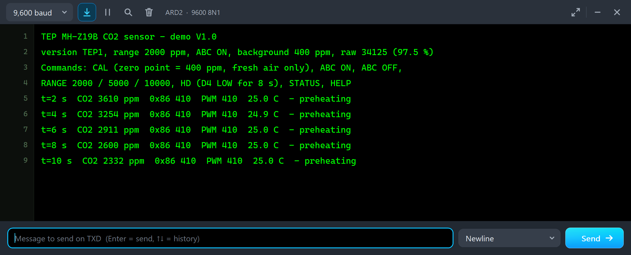
Both UNOs have the serial monitor built in, and it opens at Run. The screenshots use its Simple interface. The library's check passes, the sensor reports its version, range, ABC, background and raw value, and the readings start:
TEP MH-Z19B CO2 sensor - demo V1.0
version TEP1, range 2000 ppm, ABC ON, background 400 ppm, raw 34125 (97.5 %)
Commands: CAL (zero point = 400 ppm, fresh air only), ABC ON, ABC OFF,
RANGE 2000 / 5000 / 10000, HD (D4 LOW for 8 s), STATUS, HELP
t=2 s  CO2 3610 ppm  0x86 410  PWM 410  25.0 C  - preheating
t=4 s  CO2 3254 ppm  0x86 410  PWM 410  24.9 C  - preheating
t=6 s  CO2 2911 ppm  0x86 410  PWM 410  25.0 C  - preheating
t=8 s  CO2 2600 ppm  0x86 410  PWM 410  25.0 C  - preheating
t=10 s  CO2 2332 ppm  0x86 410  PWM 410  25.0 C  - preheating
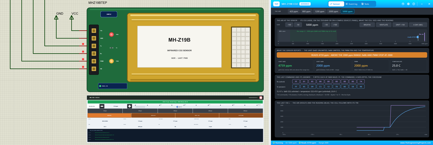
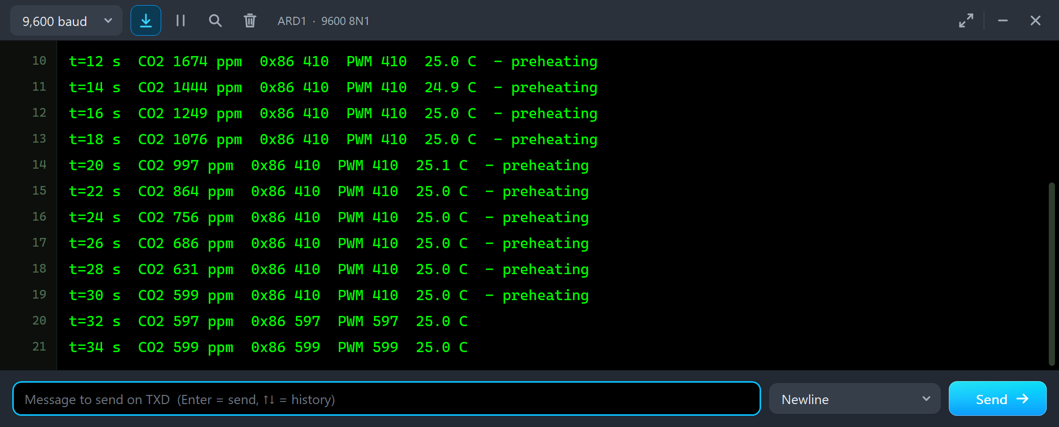
The office is at 1000 ppm, but nothing says so yet. 0x86 and the PWM pin give 410 ppm, the value the sensor holds during its preheat, and 0x85 starts far too high and falls. U2's pop-up shows the same, with the time left:
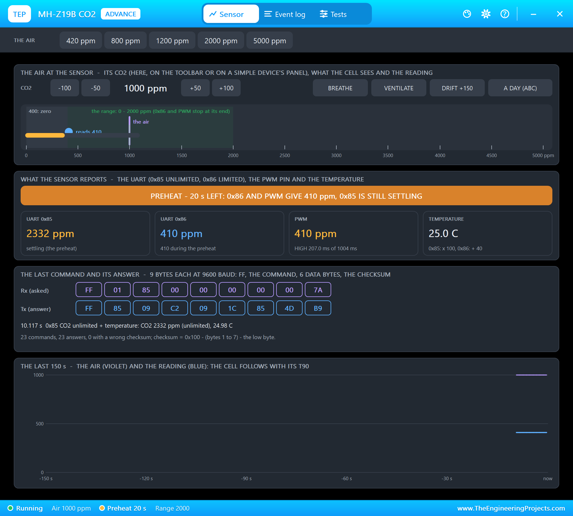
t=24 s  CO2 756 ppm  0x86 410  PWM 410  25.0 C  - preheating
t=26 s  CO2 686 ppm  0x86 410  PWM 410  25.0 C  - preheating
t=28 s  CO2 631 ppm  0x86 410  PWM 410  25.0 C  - preheating
t=30 s  CO2 599 ppm  0x86 410  PWM 410  25.0 C  - preheating
t=32 s  CO2 597 ppm  0x86 597  PWM 597  25.0 C
t=34 s  CO2 599 ppm  0x86 599  PWM 599  25.0 C
At 30 seconds the preheat is over: 0x85, 0x86 and PWM agree at about 600 ppm, the room's air. A real sensor needs 3 minutes - read nothing before that.
The Advance Pop-Up Window: an Office
At Run, U2 opens its own window, MH-Z19B CO2, with the look of our TEP Serial Monitor Advance for Proteus. It has three tabs, Sensor, Event log and Tests, plus Settings and Help behind the gear and question mark icons. The status bar at the bottom always shows the air, the reading and the range.
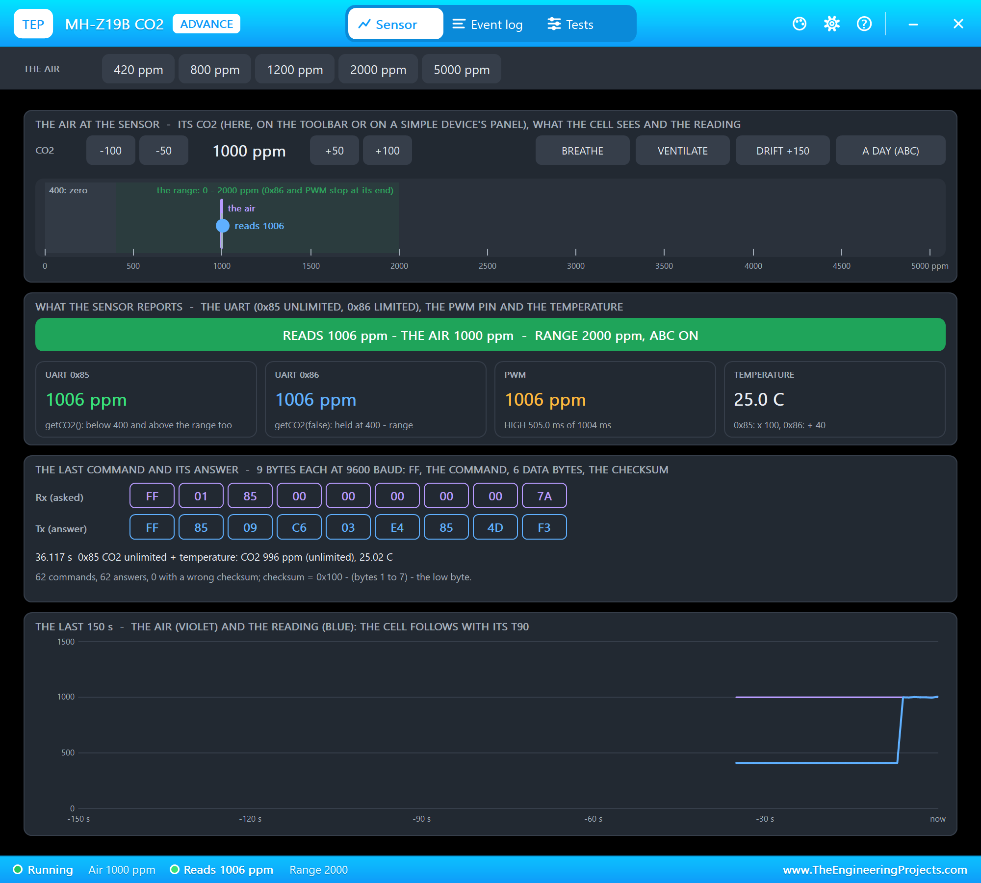
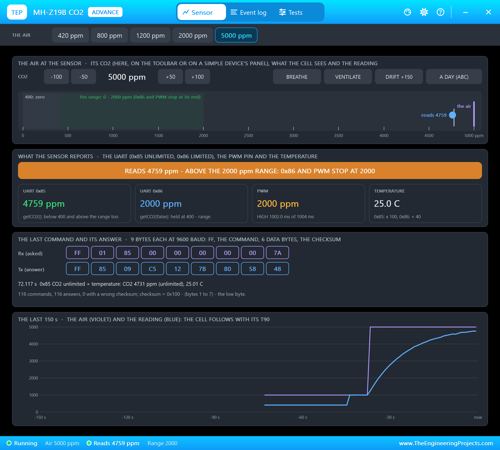
The toolbar carries the presets. The air at the sensor has -100 / -50 / +50 / +100, the four actions and a scale with the zero point, the range, the air and the reading. What the sensor reports shows the banner, 0x85, 0x86, PWM with its HIGH time, and the temperature. The last command and its answer shows the 9 bytes each way, and the last 150 s plots the air and the reading.
5000 ppm with the Range at 2000
We clicked 5000 ppm on the toolbar. The sensor's range is still 2000 ppm:
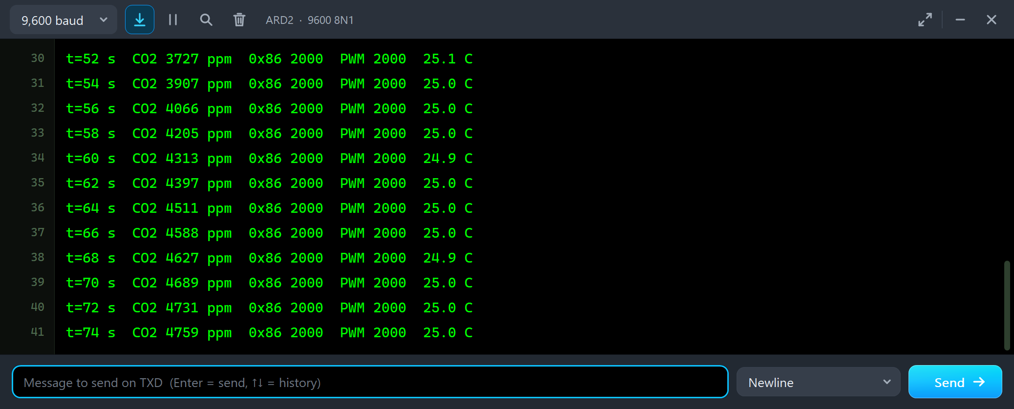
t=62 s  CO2 4397 ppm  0x86 2000  PWM 2000  25.0 C
t=64 s  CO2 4511 ppm  0x86 2000  PWM 2000  25.0 C
t=66 s  CO2 4588 ppm  0x86 2000  PWM 2000  25.0 C
t=68 s  CO2 4627 ppm  0x86 2000  PWM 2000  24.9 C
t=70 s  CO2 4689 ppm  0x86 2000  PWM 2000  25.0 C
t=72 s  CO2 4731 ppm  0x86 2000  PWM 2000  25.0 C
t=74 s  CO2 4759 ppm  0x86 2000  PWM 2000  25.0 C
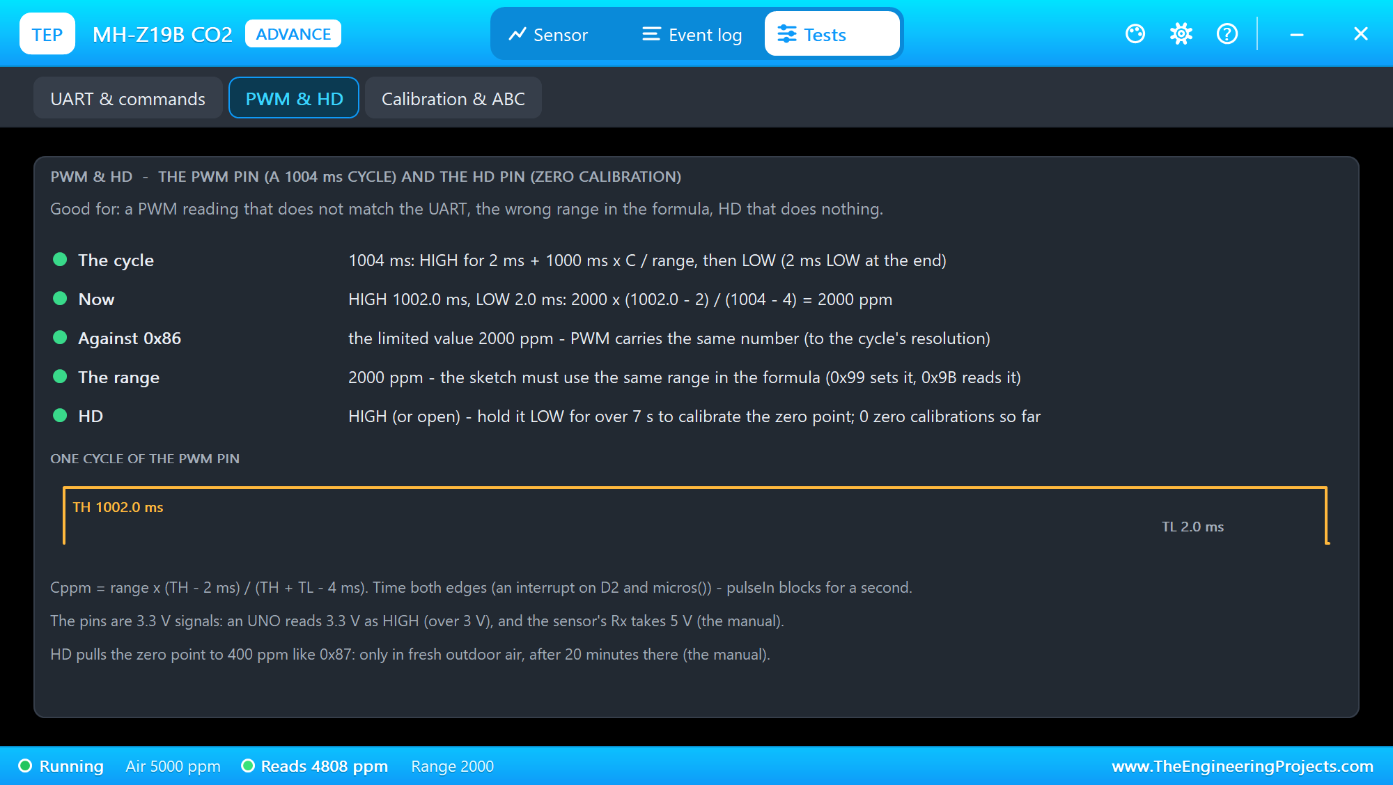
Two lessons in one picture. The reading climbs slowly - that is the response time, 30 s here. And the range matters: 0x86 and the PWM pin stop at 2000 ppm, only 0x85 shows the real 4759 ppm. A sketch that reads only 0x86 or PWM would report 2000 ppm in a room with more than twice that. The PWM & HD tool shows why:
Then we typed RANGE 5000:
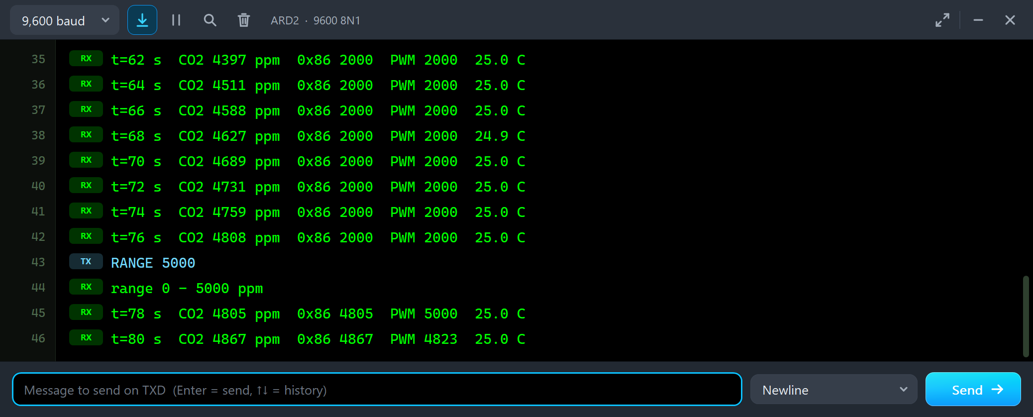
t=74 s  CO2 4759 ppm  0x86 2000  PWM 2000  25.0 C
t=76 s  CO2 4808 ppm  0x86 2000  PWM 2000  25.0 C
RANGE 5000
range 0 - 5000 ppm
t=78 s  CO2 4805 ppm  0x86 4805  PWM 5000  25.0 C
t=80 s  CO2 4867 ppm  0x86 4867  PWM 4823  25.0 C
The sensor answers, the sketch reads the new range back, and 0x86 shows 4805 ppm. Look at the first PWM value: 5000. The cycle the sketch had just timed was still a 2000 ppm cycle, HIGH for 1002 ms, and the sketch already used 5000 in the formula. One cycle later PWM agrees again.
VENTILATE
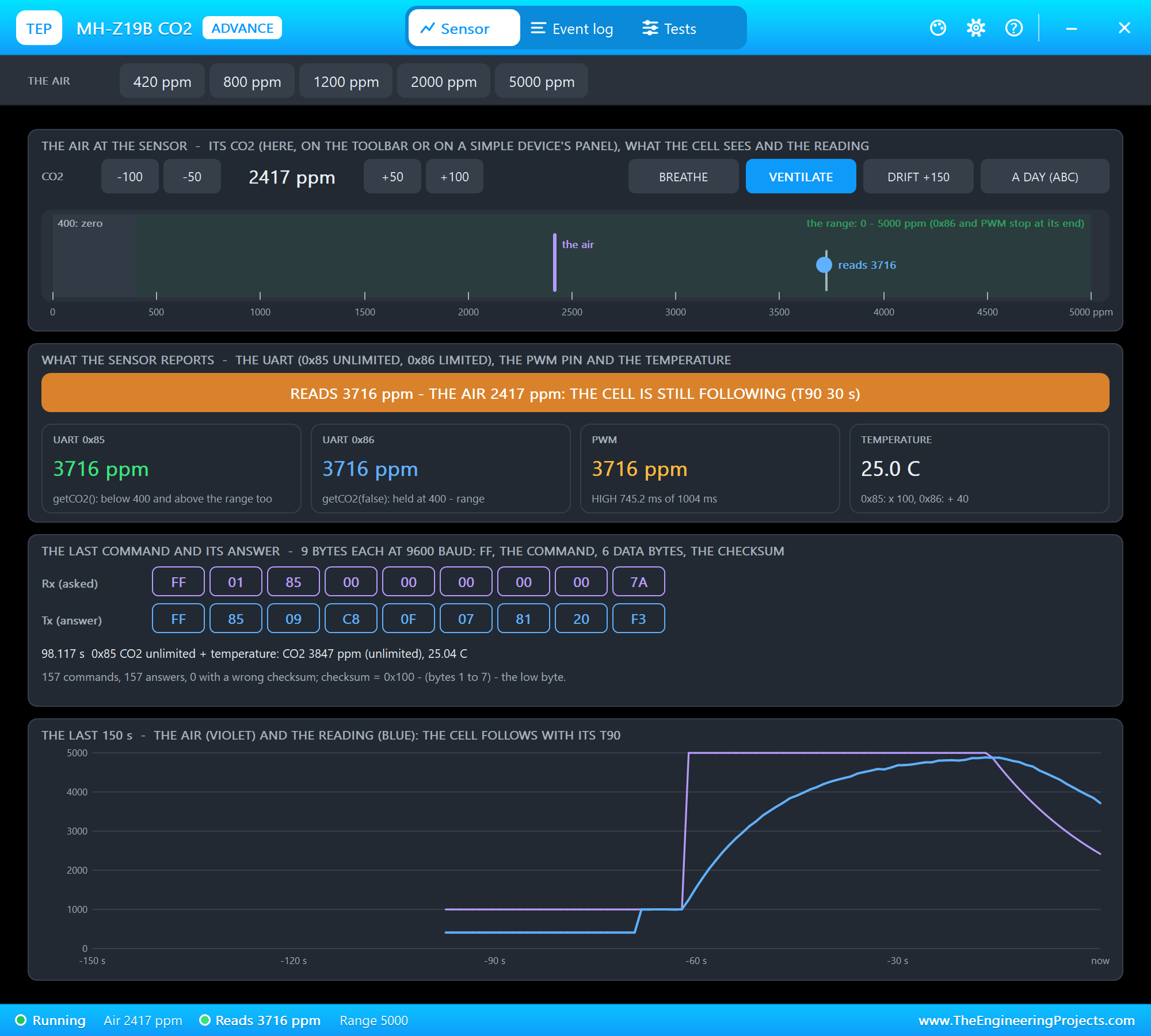

t=104 s  CO2 3229 ppm  0x86 3229  PWM 3286  25.0 C
t=106 s  CO2 3030 ppm  0x86 3030  PWM 3091  25.0 C
t=108 s  CO2 2862 ppm  0x86 2862  PWM 2908  25.1 C
t=110 s  CO2 2672 ppm  0x86 2672  PWM 2727  25.0 C
t=112 s  CO2 2523 ppm  0x86 2523  PWM 2566  24.9 C
t=114 s  CO2 2342 ppm  0x86 2342  PWM 2388  25.0 C
t=118 s  CO2 2058 ppm  0x86 2058  PWM 2091  25.0 C
t=122 s  CO2 1804 ppm  0x86 1804  PWM 1831  24.9 C
t=126 s  CO2 1595 ppm  0x86 1595  PWM 1612  25.0 C
VENTILATE opens a window: the room's air goes to 420 ppm, outdoor air, and the reading follows it down. Here the PWM value is a little higher than the UART one on every line - while the CO2 falls fast, the PWM cycle the sketch timed is one second older than the reading 0x86 answers with.
The Test Tools
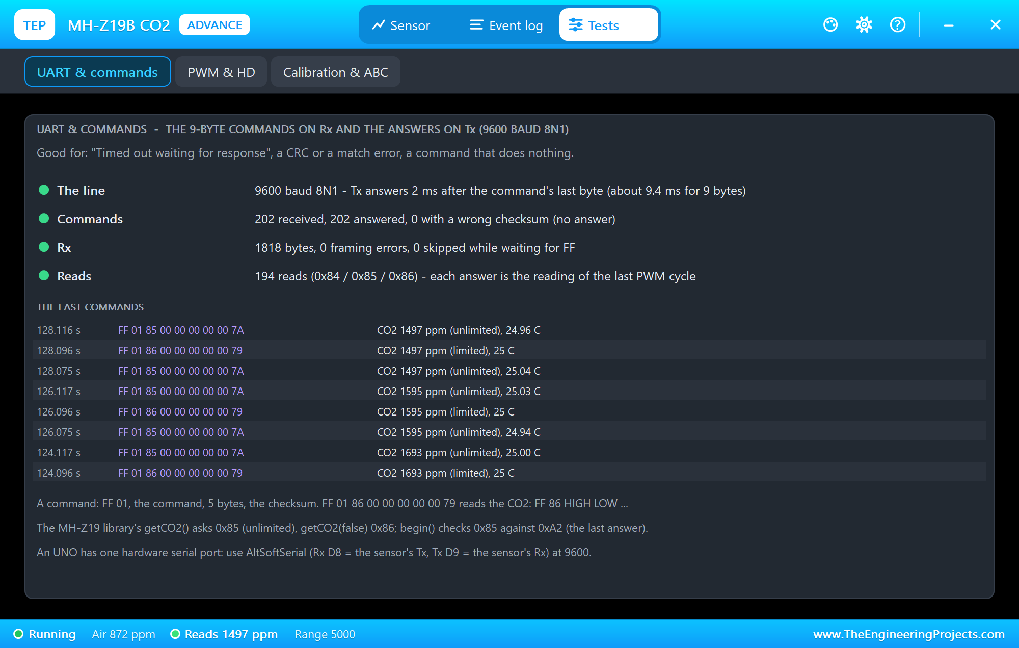
The UART & commands tool is the one to open when the library prints "Timed out waiting for response": it counts the commands, the answers, the wrong checksums and the framing errors on Rx, and lists the last commands with their bytes. Here the sketch asks 0x85, 0x86 and 0x85 again (for the temperature) every 2 seconds.
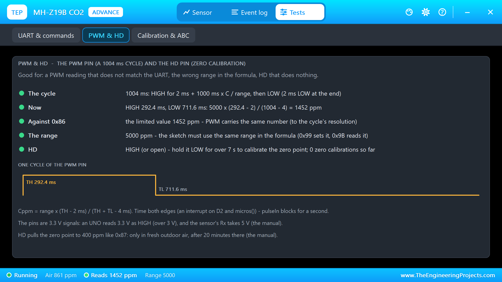
The PWM & HD tool works the manual's formula out with the current HIGH and LOW times, compares it with 0x86, and shows the HD pin. The third tool, Calibration & ABC, comes later with the calibrations.
The Event Log
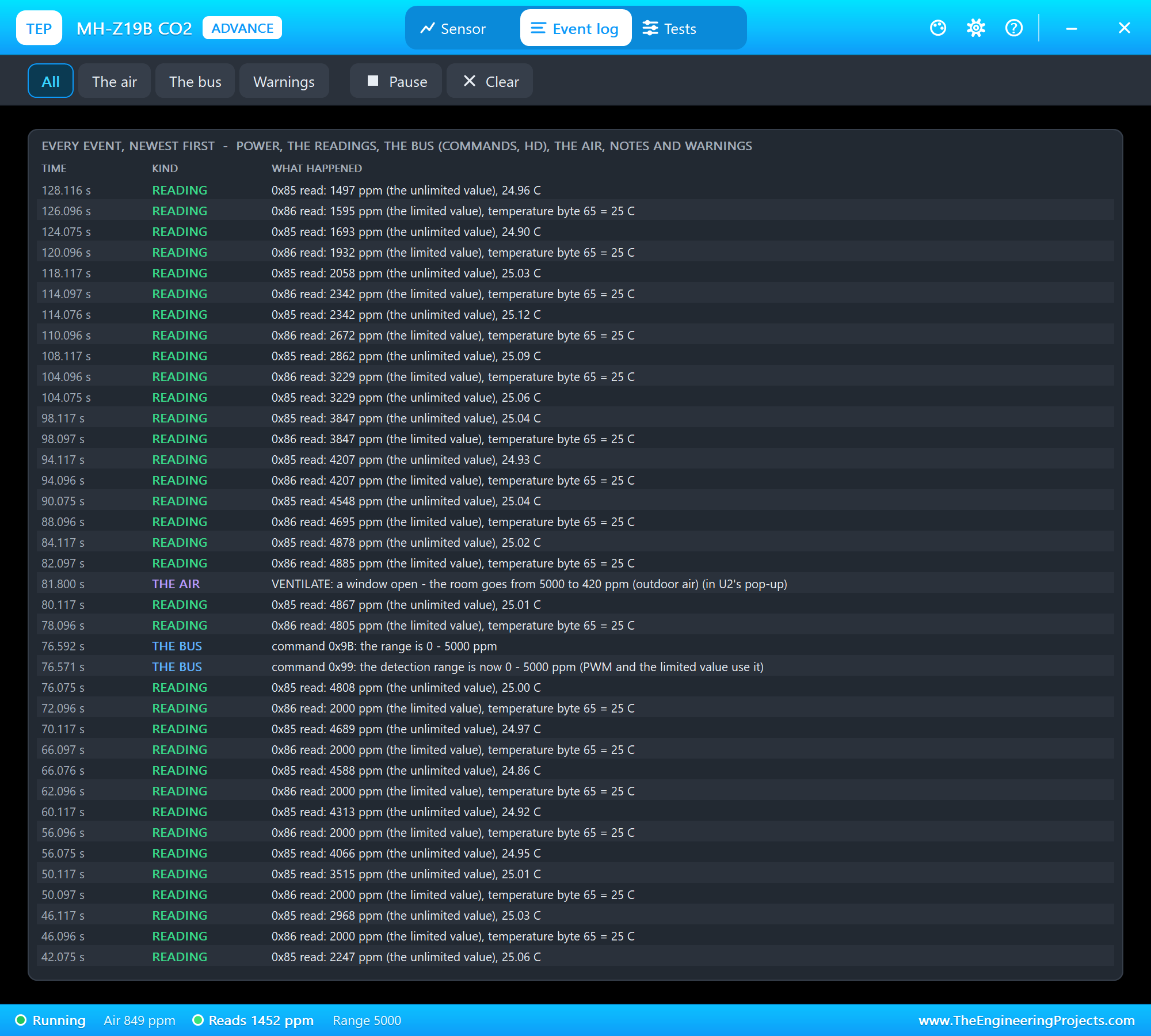
The Event log lists everything that happened, newest first: power, the readings, the bus (commands and HD), the air, notes and warnings. Filter it by the air, the bus or warnings, pause it, or clear it.
A Room on the STATUS Panel
Now node 1. We clicked the buttons of U1's STATUS panel with the mouse while the simulation ran. First BREATHE - a breath right on the window:
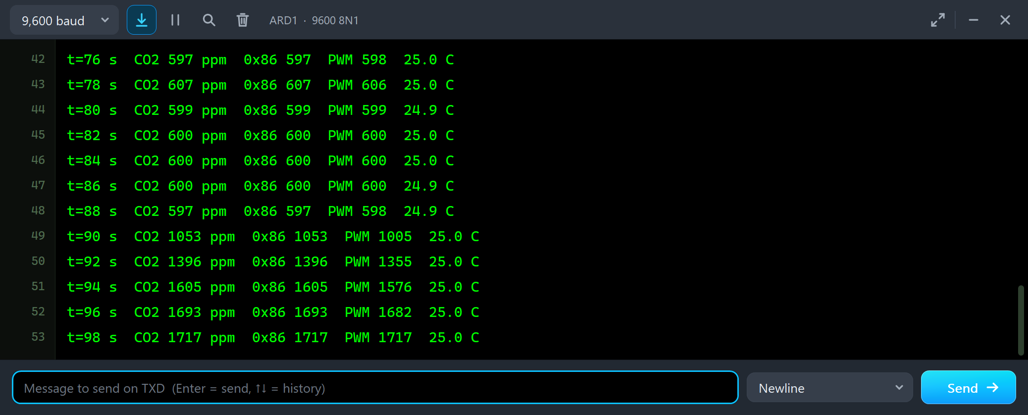
t=84 s  CO2 600 ppm  0x86 600  PWM 600  25.0 C
t=86 s  CO2 600 ppm  0x86 600  PWM 600  24.9 C
t=88 s  CO2 597 ppm  0x86 597  PWM 598  24.9 C
t=90 s  CO2 1053 ppm  0x86 1053  PWM 1005  25.0 C
t=92 s  CO2 1396 ppm  0x86 1396  PWM 1355  25.0 C
t=94 s  CO2 1605 ppm  0x86 1605  PWM 1576  25.0 C
t=96 s  CO2 1693 ppm  0x86 1693  PWM 1682  25.0 C
t=98 s  CO2 1717 ppm  0x86 1717  PWM 1717  25.0 C
A breath carries tens of thousands of ppm of CO2, but it thins out within seconds, and the sensor is slow. It reaches 1717 ppm while the breath is already fading - put a CO2 monitor where people do not breathe on it. On the way up the PWM value trails the UART by one cycle again.
DRIFT and ABC
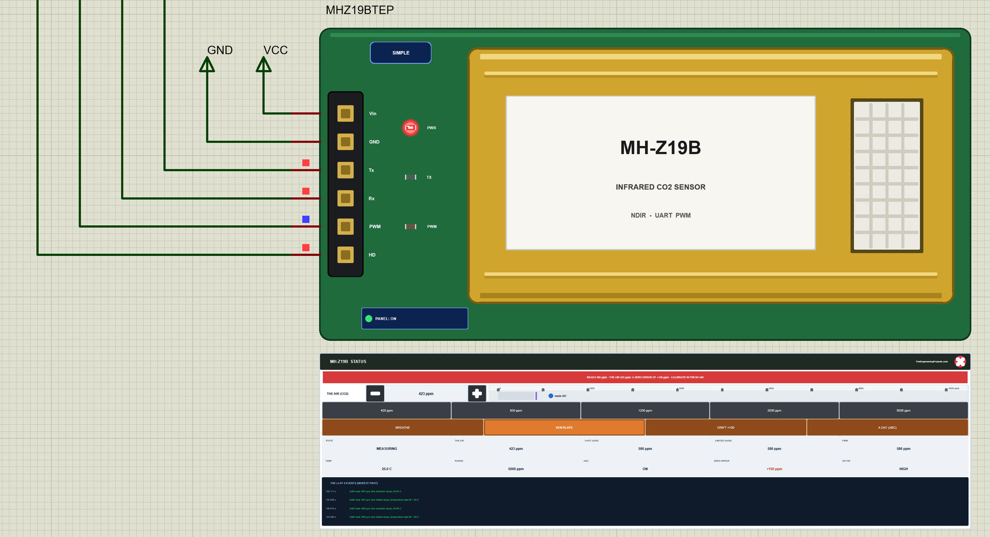
A real sensor ages and its zero point drifts. We clicked DRIFT +150, then VENTILATE, and let the room air out:
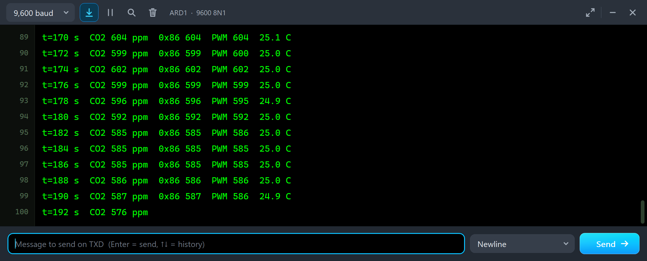
t=170 s  CO2 604 ppm  0x86 604  PWM 604  25.1 C
t=172 s  CO2 599 ppm  0x86 599  PWM 600  25.0 C
t=174 s  CO2 602 ppm  0x86 602  PWM 602  25.0 C
t=176 s  CO2 599 ppm  0x86 599  PWM 599  25.0 C
t=178 s  CO2 596 ppm  0x86 596  PWM 595  24.9 C
t=180 s  CO2 592 ppm  0x86 592  PWM 592  25.0 C
t=182 s  CO2 585 ppm  0x86 585  PWM 586  25.0 C
t=184 s  CO2 585 ppm  0x86 585  PWM 585  25.0 C
t=186 s  CO2 585 ppm  0x86 585  PWM 585  25.0 C
The room is down to about 425 ppm, but the sensor still reads about 585 ppm: everything is 150 ppm too high. This is what ABC, automatic baseline correction, is for. Every 24 hours the sensor takes the lowest reading of the day as 400 ppm. Nobody waits a day in a simulation, so A DAY (ABC) runs it at once:
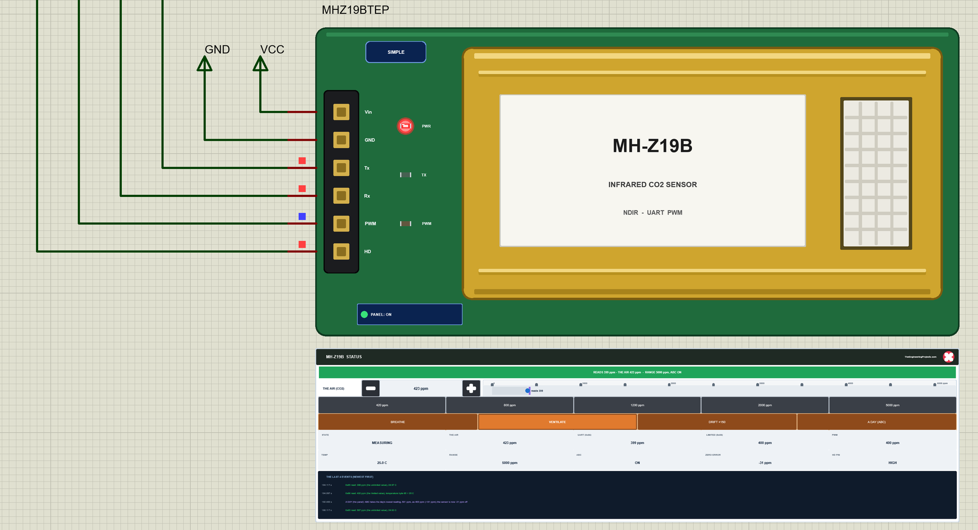
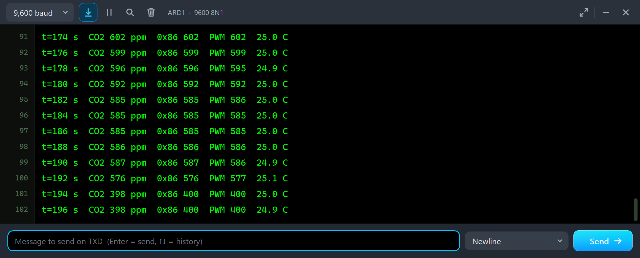
t=186 s  CO2 585 ppm  0x86 585  PWM 585  25.0 C
t=188 s  CO2 586 ppm  0x86 586  PWM 586  25.0 C
t=190 s  CO2 587 ppm  0x86 587  PWM 586  24.9 C
t=192 s  CO2 576 ppm  0x86 576  PWM 577  25.1 C
t=194 s  CO2 398 ppm  0x86 400  PWM 400  25.0 C
t=196 s  CO2 398 ppm  0x86 400  PWM 400  24.9 C
ABC took the day's lowest reading, 581 ppm, as 400 ppm, and the drift is gone: from 576 to 398 ppm. Not quite to the air's 423 ppm - the lowest reading of the day came while the room was still airing out, so the sensor is now 31 ppm low, within its accuracy. That is ABC's condition: the room must get fresh air at least once a day. In a greenhouse or a closed room that never does, ABC pulls the readings down day after day - switch it off there with ABC OFF.
A Zero Point in the Wrong Air
Next we made the classic mistake. We clicked 1200 ppm, waited for the sensor, and typed CAL. The sensor did what it was told: 1200 ppm now read 400 ppm. Then we clicked 420 ppm:
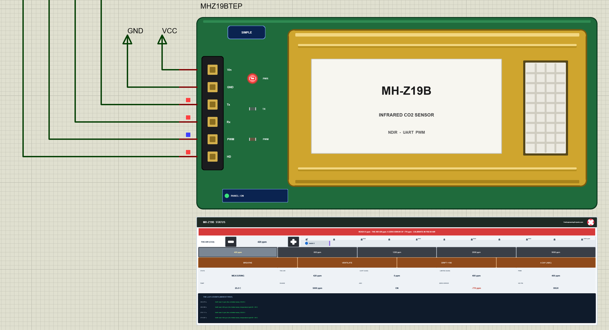
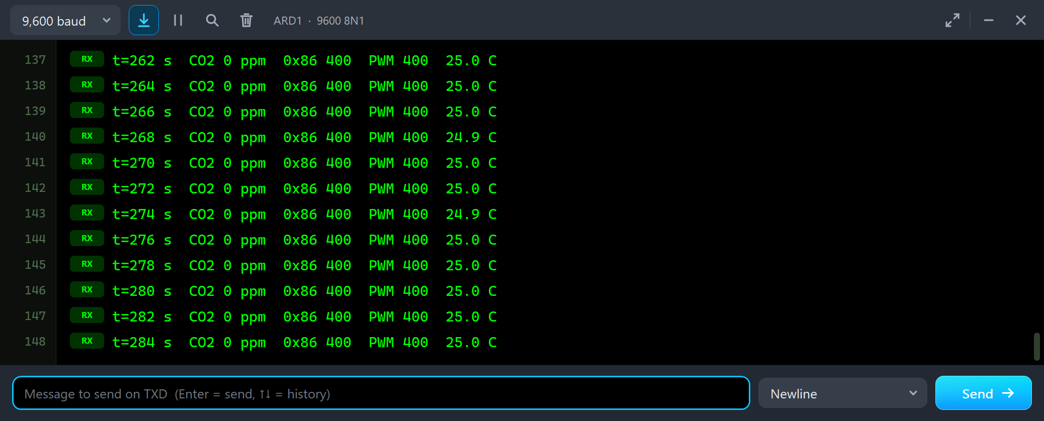
t=278 s  CO2 0 ppm  0x86 400  PWM 400  25.0 C
t=280 s  CO2 0 ppm  0x86 400  PWM 400  25.0 C
t=282 s  CO2 0 ppm  0x86 400  PWM 400  25.0 C
t=284 s  CO2 0 ppm  0x86 400  PWM 400  25.0 C
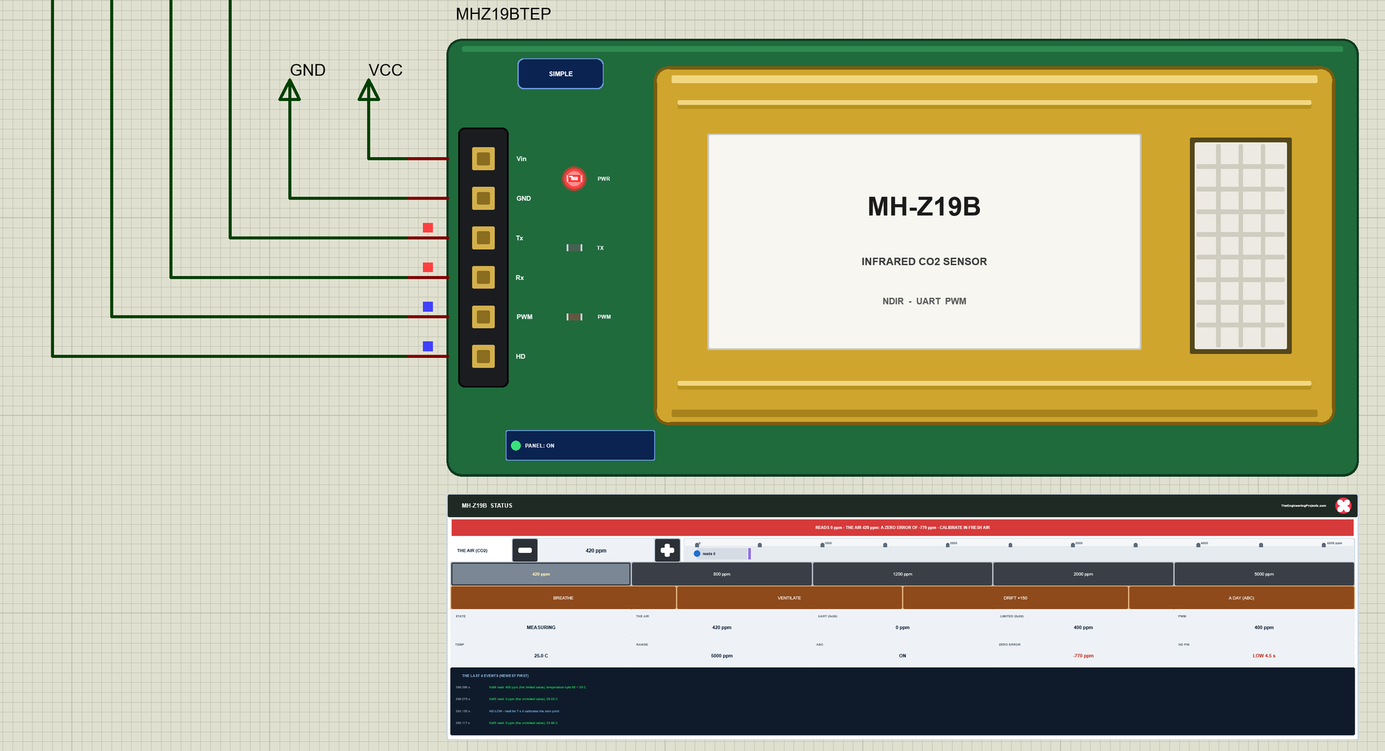
In fresh air the sensor now reads 0 ppm on 0x85, and the panel shows a zero error of -770 ppm. 0x86 and PWM hide it: they never go below 400 ppm, so a sketch that reads only 0x86 would believe the air is perfect. This is why the manual wants a zero calibration only after 20 minutes in fresh outdoor air - and why 0x85 is worth reading. The Calibration tool on node 2, which had aired out to 420 ppm by then, gives the right moment:
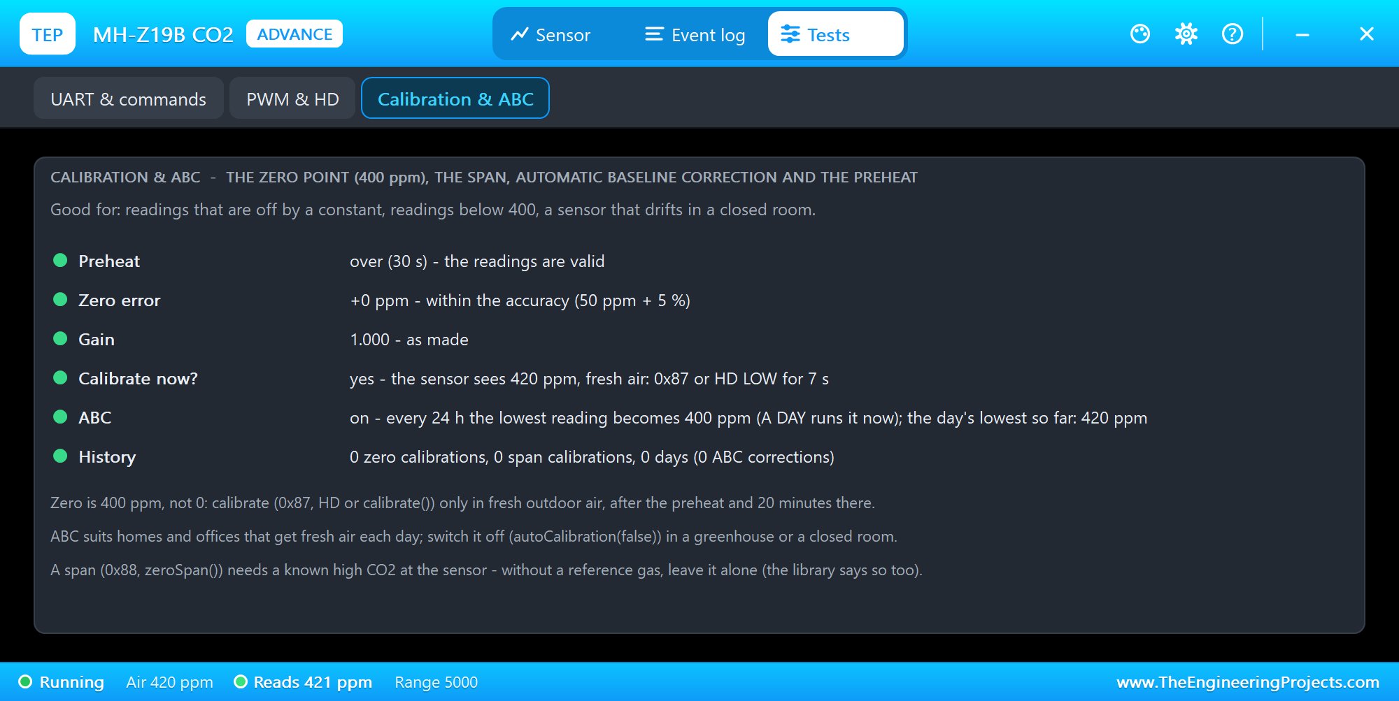
The Calibration & ABC tool shows the preheat, the zero error, the gain, ABC with the day's lowest reading, and a verdict: Calibrate now? - yes only after the preheat, in fresh air. Here it said yes, and we typed CAL in ARD2's monitor:
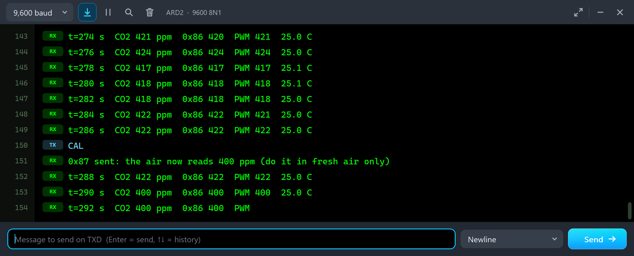
t=280 s  CO2 418 ppm  0x86 418  PWM 418  25.1 C
t=282 s  CO2 418 ppm  0x86 418  PWM 418  25.0 C
t=284 s  CO2 422 ppm  0x86 422  PWM 421  25.0 C
t=286 s  CO2 422 ppm  0x86 422  PWM 422  25.0 C
CAL
0x87 sent: the air now reads 400 ppm (do it in fresh air only)
t=288 s  CO2 422 ppm  0x86 422  PWM 422  25.0 C
t=290 s  CO2 400 ppm  0x86 400  PWM 400  25.0 C
Outdoor air of about 420 ppm became 400 ppm, the sensor's zero point - right within its accuracy.
HD: the Zero Point by Hand
Back to node 1, which still reads 0 ppm in fresh air. The manual's other way to calibrate the zero point is the HD pin: LOW for over 7 seconds. We typed HD:
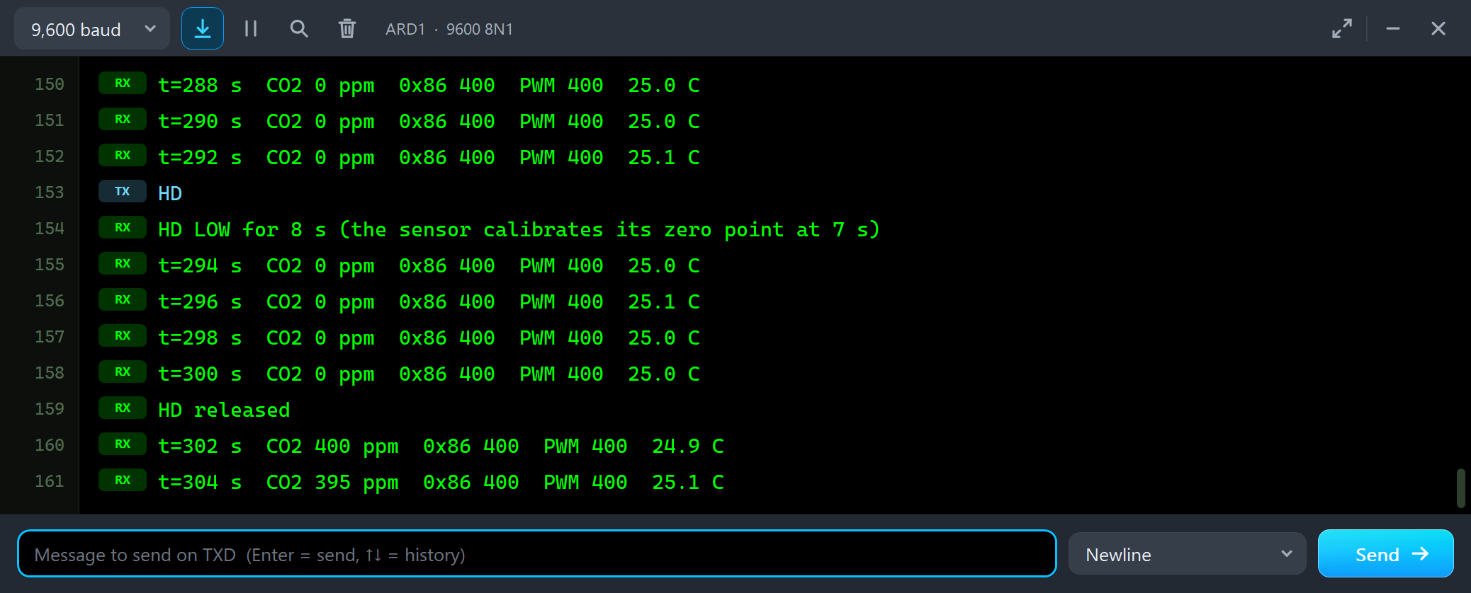
t=290 s  CO2 0 ppm  0x86 400  PWM 400  25.0 C
t=292 s  CO2 0 ppm  0x86 400  PWM 400  25.1 C
HD
HD LOW for 8 s (the sensor calibrates its zero point at 7 s)
t=294 s  CO2 0 ppm  0x86 400  PWM 400  25.0 C
t=296 s  CO2 0 ppm  0x86 400  PWM 400  25.1 C
t=298 s  CO2 0 ppm  0x86 400  PWM 400  25.0 C
t=300 s  CO2 0 ppm  0x86 400  PWM 400  25.0 C
HD released
t=302 s  CO2 400 ppm  0x86 400  PWM 400  24.9 C
t=304 s  CO2 395 ppm  0x86 400  PWM 400  25.1 C
After 7 seconds the sensor calibrated, and once the next reading came in the 0 became 400 ppm. The node was in 420 ppm air, so it now reads about 20 ppm low - again within its accuracy. STATUS shows the settings:
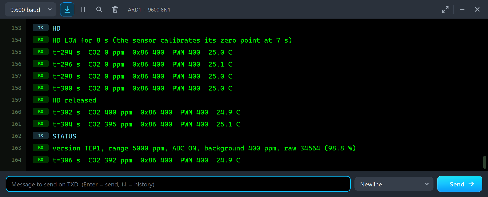
STATUS
version TEP1, range 5000 ppm, ABC ON, background 400 ppm, raw 34564 (98.8 %)
t=306 s  CO2 392 ppm  0x86 400  PWM 400  24.9 C
The version is TEP1, the model's own - not a real firmware number. The raw value, about 35000, is what the library calls the light through the chamber.
The Simulation Log
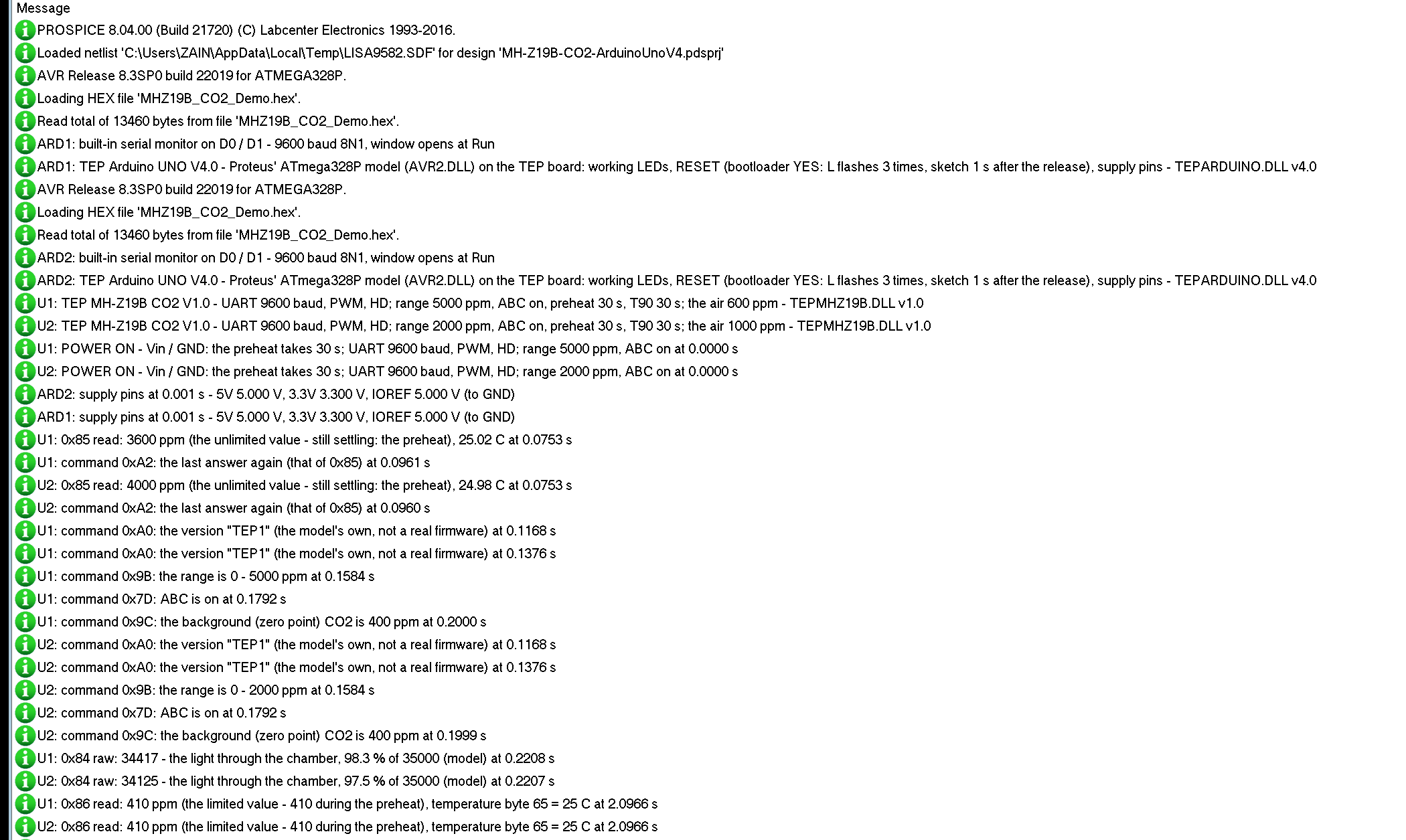
The sensors also write to the simulation log of Proteus, with the exact simulation time. This part shows U1 and what the MH-Z19 library asked at the start:
U1: TEP MH-Z19B CO2 V1.0 - UART 9600 baud, PWM, HD; range 5000 ppm, ABC on, preheat 30 s, T90 30 s; the air 600 ppm - TEPMHZ19B.DLL v1.0
U1: POWER ON - Vin / GND: the preheat takes 30 s; UART 9600 baud, PWM, HD; range 5000 ppm, ABC on at 0.0000 s
U1: 0x85 read: 3600 ppm (the unlimited value - still settling: the preheat), 25.02 C at 0.0753 s
U1: command 0xA2: the last answer again (that of 0x85) at 0.0961 s
U1: command 0xA0: the version "TEP1" (the model's own, not a real firmware) at 0.1168 s
U1: command 0x9B: the range is 0 - 5000 ppm at 0.1584 s
U1: command 0x7D: ABC is on at 0.1792 s
U1: command 0x9C: the background (zero point) CO2 is 400 ppm at 0.2000 s
U1: 0x84 raw: 34417 - the light through the chamber, 98.3 % of 35000 (model) at 0.2208 s
U1: 0x86 read: 410 ppm (the limited value - 410 during the preheat), temperature byte 65 = 25 C at 2.0966 s
begin() asks 0x85 at 75 ms and 0xA2 at 96 ms, then the version twice (once in begin(), once for the status line), the range, ABC, the background and the raw value - all in the first quarter of a second. Proteus logs the first 300 reading lines; the Event log has the rest.
How the Model Works
The sensor is a digital model. Vin and GND switch it on and off. Rx is an input: the model decodes every byte at 9600 baud and answers a complete command 2 ms later on Tx, every bit at its exact time. PWM is an output with the 1004 ms cycle, and HD an input with its 7 seconds. Inside, the cell follows the air with a first-order lag set by T90, and each PWM cycle gives a new reading: the zero point at 400 ppm, the gain, the zero error and a little noise. Proteus calls the model only at its next event - a bit, an edge, the end of a byte - so it costs little time.
Troubleshooting
- "Failed to verify connection" or "Timed out waiting for response": Tx and Rx swapped (the sensor's Tx goes to D8), no power, or the wrong baud rate - the UART & commands tool counts the framing errors.
- "- preheating", 0x86 stuck at 410: the preheat is not over - 3 minutes on a real sensor.
- The reading lags behind the air: the response time; a breath shows only part of its CO2.
- 0x85 reads 0 or below the air while 0x86 says 400: the zero point was set in the wrong air - calibrate again in fresh air. A constant offset: a drift, or ABC in a room that never gets fresh air.
- 0x86 and PWM stop at 2000 (or 5000): the range - RANGE 5000 or 10000.
- The PWM reading is off: the sketch uses another range in the formula than the sensor.
- No part or no monitor: TEPMHZ19B.DLL or TEPARDUINO.DLL is missing from MODELS and the project folder; a closed monitor opens again with a click on the UNO's USB port.
Things to Know Before Using a Real MH-Z19B
- Power: 4.5 to 5.5 V and 150 mA peaks for the lamp - a weak supply reads low or not at all.
- Levels: the signals are 3.3 V; an UNO reads the 3.3 V HIGH of Tx and PWM fine, and the manual says Rx and HD take 5 V.
- Handle it gently: do not press on the gold chamber, keep the window free, and keep the sensor away from heat, sunlight and your breath.
- Calibration: zero only after 20 minutes in fresh outdoor air; leave ABC on in rooms that get fresh air every day and off elsewhere; never use a span calibration without a known reference gas.
Limitations of the Simulation
- Not modelled: the analog output Vo (the part has no Vo pin), the lamp and the light itself, the supply voltage and current, the 3.3 V level, humidity, pressure and heat, ageing beyond DRIFT, the accuracy limits of a real unit, and how ABC acts over weeks.
- The model's own choices: the set commands answer FF cmd 01 00 ... (the manual lists no answer, but the library waits for one), the answer 2 ms after a command, a new reading each PWM cycle, the noise, the values during the preheat (410 on 0x86 and PWM, 0x85 settling from 3000 ppm above), the raw value and the version TEP1.
- The badge, the LEDs, the panel button and the panels are TEP additions.
- The model is our own, written from Winsen's user's manual and the public MH-Z19 library. This library is not made or endorsed by Winsen or by Labcenter.
- Licences: the demo sketch uses MH-Z19 1.5.4 by Jonathan Dempsey (LGPL-3.0) and AltSoftSerial 1.4 by Paul Stoffregen (MIT License); neither is in the package - the README has the links, the licence texts and how to rebuild the HEX file. The HEX file also contains the Arduino AVR core 1.8.6 with LGPL-licensed code; the source link is in the README.
- Tested in Proteus 8.5 in October 2026 (the demo as shipped on two Arduino UNO V4.0 boards with their built-in monitors: the preheat on both; 5000 ppm above the range, RANGE 5000, VENTILATE, the three tools and CAL in outdoor air on the Advance sensor; BREATHE, DRIFT +150, VENTILATE, A DAY, CAL in 1200 ppm, HD and STATUS on the Simple one with the mouse, the red X and PANEL; 318.1 s of simulation took 722 s, about 0.44 x real time with the pop-up and both monitors open). Proteus 7 is not supported.
So, that was all about the MH-Z19B CO2 Sensor Library for Proteus V1.0. I hope the preheat, the range, the zero point and ABC are clear now, and that your CO2 monitor or ventilation controller works from the first run. If you use the MH-Z19B CO2 Sensor Library for Proteus in a project, please share it in the comments or in our forum, and if you have any questions, ask in the comments and I will help you out. Till the next tutorial, take care and have fun!