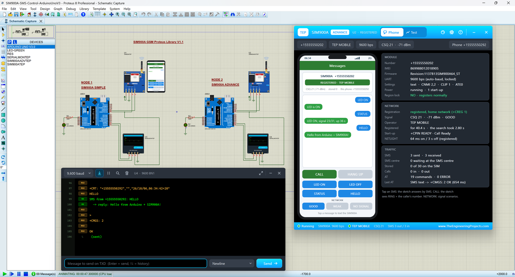
Hello friends, I hope you all are doing great. Today, I am going to share the new SIM900A GSM Library for Proteus V1.1. The SIM900A on its blue "SIM900A MINI" board is one of the cheapest ways to give an Arduino its own phone number: it sends and receives SMS and tells your sketch who is calling. It is also famous for a nasty surprise: in many countries, a brand-new SIM900A never connects to the network. With this SIM900A Library for Proteus, you can build your GSM project on your PC, see every line the module answers and even reproduce that region lock before you buy any hardware.
You get two devices in one library: SIM900A Simple, with a virtual smartphone next to the module on the schematic, and SIM900A Advance, with a pop-up window that holds the phone and four measured GSM test tools. The complete SIM900A Proteus simulation has two Arduino UNOs that switch LEDs by SMS, reject calls and show the module's raw replies in our TEP Serial Monitor.
NOTICE: Our SIM900A model does not replay a recorded script: it switches itself on like the real mini board, learns your baud rate, says Call Ready only after the network, confirms SMS the SIM900 way and can even refuse the network like a region-locked module. It took our team a lot of research, test runs and redesigns, and this library is a tribute to that effort. Please tell us what you think in the comments below or in the SIM900A Library board of our forum. And if our free libraries help you in your studies or work, you can buy us a coffee. So, let's get started with the SIM900A Library for Proteus:
What is the SIM900A GSM Module?
The SIM900A is a dual-band GSM / GPRS module (900 / 1800 MHz) made by SIMCom. Most people buy it on the blue SIM900A MINI board (V3.8.2, about 49 x 50 mm) with a flip SIM holder, an SMA jack for a rubber-duck antenna and a small TTL header. Your Arduino controls it over a UART (the two-wire TX / RX serial port) with AT commands: short text commands such as AT+CSQ (signal quality) or AT+CMGS (send an SMS). It sends and receives SMS, shows the caller's number, answers or rejects calls, and reports the signal, the operator and the network time.
SIM900 or SIM900A?
The SIM900A is the "A" version of SIMCom's SIM900. Both use the same AT commands, and both even answer ATI with "SIM900 R11.0". The difference is the firmware:
| Stock SIM900A | SIM900A with SIM900 firmware | |
|---|---|---|
| AT+CGMM answers | SIMCOM_SIM900A | SIMCOM_SIM900 |
| Firmware build (AT+CGMR) | for example 1137B13SIM900A64_ST | for example 1137B09SIM900B32_ST (32 Mbit flash) |
| Networks | Only in its Asian country list (from build 1137B06SIM900A32_ST on) | No country list |
| Bands | GSM 900 / 1800 MHz | The same module, the same bands |
Our model is written from SIMCom's SIM900 AT Command Manual, so if you need a SIM900 Proteus model, your SIM900 sketches will run on it too; only the identity strings say SIM900A.
GSM Terms You Will See in This Article
| Term | Meaning |
|---|---|
| AT command | A text command to the module, ending with a carriage return (CR). The module answers OK or ERROR. |
| URC | "Unsolicited result code": a line the module sends by itself, such as RING, +CLIP, +CMT or Call Ready |
| Auto-bauding | The module learns your UART speed from the first "AT" it receives (upper-case A on the SIM900A) |
| +CPIN | The SIM state. READY = usable; PH-NET PIN = the network is not allowed (the region lock) |
| Registration | The module has logged in to the network: +CREG: 0,1. 0,2 means "still searching". |
| Call Ready | The URC the SIM900A sends once it is registered: now it can call and text |
| CSQ | Signal quality from 0 to 31; the SIM900 reports +CSQ: 0,0 without network |
| RI | "Ring indicator": LOW while a call rings, a short LOW pulse for each new SMS |
| NETLIGHT | The network LED: 64 ms on / 800 ms off while searching, every 3 s when registered |
| SMS centre | The part of the network that keeps an SMS until the receiver can be reached |
What's New in SIM900A Library for Proteus V1.1
- Its own library: v1.0 shipped the SIM900A together with the SIM800C; now it has its own package and article, and both share the model
TEPSIMCOM.DLL. - Two devices: SIM900A Simple (
SIM900ATEP) and SIM900A Advance (SIM900AADVTEP, with its own default numbers +15555550202 / +15555550292). - Board: a new red PWR LED, a ring LED and a tip lamp on the duck antenna, a PANEL / OPEN PANEL button and a SIMPLE / ADVANCE badge; D6 moved off the SMA jack it touched in v1.0.
- Model: the network search takes 2.2 - 3.2 s (v1.0: always 3 s), every SMS takes its own time on the network, AT+CFUN=1,1 sends its whole OK before it restarts, and the phone shows 60 characters per message (v1.0: 32).
- Demo: TEP Serial Monitors that also show the module's raw replies, and a sketch that takes AT commands from the monitor and sets the module up again after a restart.
- Lighter package: about 1.5 MB, without the C++ source code.
SIM900A Library for Proteus: Simple vs Advance
| Feature | Simple | Advance |
|---|---|---|
| Full SIM900A model (AT commands, SMS, calls, network, region lock) | ✔ | ✔ |
| PWR, D5 (RI) and D6 (NETLIGHT) LEDs, antenna ring and tip lamp, waves | ✔ | ✔ |
| Virtual phone drawn on the schematic | ✔ | ✘ |
| Phone in a pop-up window you can move, resize and minimise | ✘ | ✔ |
| MODULE, NETWORK and TRAFFIC cards (with the region lock state) | ✘ | ✔ |
| Network, SMS round trip, Call and AT check tools | ✘ | ✔ |
| TEP Dark / Light theme, text size, Help page with Copy diagnostics | ✘ | ✔ |
| Same device name as v1.0 (old designs keep working) | ✔ | ✘ |
Both run the same model with the same properties. Pick Simple to see the phone beside your circuit, and Advance when the sheet is full or you want measured numbers. The demo uses both.
Download SIM900A Library for Proteus
Click the button below to download SIM900A-GSM-Library-for-Proteus-v1.1.zip (about 1.5 MB, without the C++ source code):
SIM900A GSM Library for Proteus V1.1- README.txt: a detailed guide to the files, the model and the demo.
- Proteus Library Files:
TEPSIM900A.LIB(both devices),TEPSERIALMON.LIBand our Arduino UNO libraryArduinoV3TEP.LIB/ArduinoV3TEP.IDX. - Proteus Model Files:
TEPSIMCOM.DLLandTEPSERIALMON.DLL. - Proteus Simulation: the demo project, the .hex file and copies of both DLLs.
- Arduino Code: the demo sketch and AltSoftSerial 1.4 (MIT licence).
TEPSIMCOM.DLL is shared with our SIM800C Library for Proteus: both packages ship the identical file. So you can install either library or both, use them together, and even let a SIM900A and a SIM800C text each other. Your v1.0 designs keep working too.
If you don't have Proteus yet, read How to Download and Install Proteus 7 and 8. New to libraries? Follow How to Install a New Library in Proteus.
How to Install SIM900A Library for Proteus
- Close Proteus and extract the whole zip file.
- Copy the four files from Proteus Library Files into the LIBRARY folder, usually
C:\Program Files (x86)\Labcenter Electronics\Proteus 8 Professional\LIBRARY(on some PCsC:\ProgramData\Labcenter Electronics\Proteus 8 Professional\LIBRARY). - Copy
TEPSIMCOM.DLLandTEPSERIALMON.DLLinto the MODELS folder. - Start Proteus, press P and search for SIM900A. You get the Simple and the Advance device (category Peripherals > Wireless).
Updating from v1.0? Replace TEPSIM900A.LIB and TEPSIMCOM.DLL, and delete any TEPSIM900A.IDX from the LIBRARY folder. Old designs keep their v1.0 symbol; re-pick the part to get the v1.1 board. Tested in Proteus 8.5; Proteus 7 is not supported.
SIM900A MINI Board in Proteus
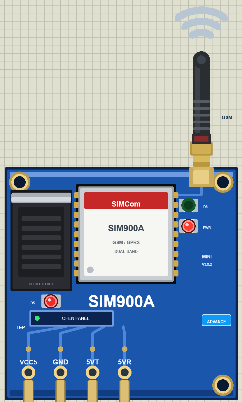
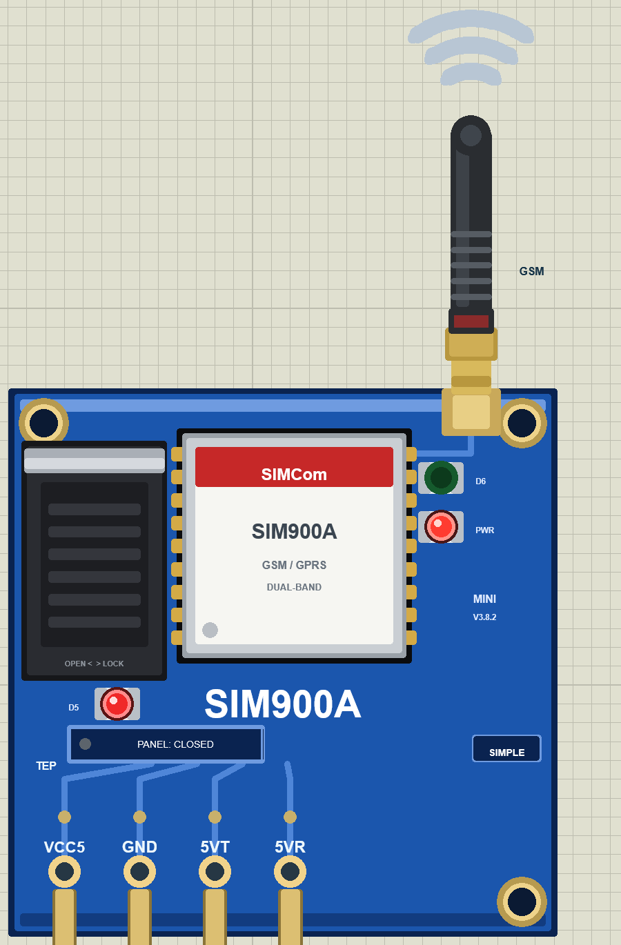
We drew the module as a clean TEP board in the blue of the real SIM900A MINI: the flip SIM holder, the SIMCom SIM900A can, the SMA jack with a black rubber-duck antenna, the "MINI V3.8.2" print and three LEDs. Here is the SIM900A Advance with its pop-up closed:
Pinout
| Pin | Function | Demo connection |
|---|---|---|
| VCC5 | 5 V supply input (the board's regulator feeds the module) | Supply |
| GND | Ground | GND |
| 5VT | Module TXD at 5 V level: answers and URCs | Arduino D8 and Serial Monitor RXD2 |
| 5VR | Module RXD at 5 V level: AT commands from the Arduino | Arduino D9 |
The real header also has 3VT / 3VR (the same lines at 3.3 V level) and, on some versions, VCC4 and VCC_MCU, which a 5 V UNO does not need. Notice that there is no RI pin and no power or reset pin: the wiring is very simple, but your sketch must work a little differently.
LEDs, Antenna and Waves
| Indicator | What it shows |
|---|---|
| PWR (red, new in v1.1) | On whenever the board has 5 V, even while the module restarts |
| D5 (red) = RI | Lit at idle, dark while a call rings, a short off-flicker for each new SMS |
| D6 (green) = NETLIGHT | Off while the module is off; 64 ms on / 800 ms off while searching; 64 ms on / 3 s off when registered |
| The duck's ring LED and tip lamp | Orange while the module sends (SMS, call set-up), green while it receives, both in turn during a call |
| Waves above the antenna | Ripple out while sending, in while receiving |
D5 deserves a closer look. The SIM900A MINI does not bring RI out to its header; it only drives LED D5. So your sketch learns about calls from the RING and +CLIP lines on the UART, and that is what our demo sketch does.
A Board That Switches Itself On
The mini board holds the module's power key (PWRKEY) low, so the SIM900A switches on by itself 1 s after power-up, and our model does the same. Then:
- It sends the SIMCom sync bytes (00 49 49 49 49 FF FF FF FF) at 115200 bps. At 9600 baud they look like a few garbage characters, which is normal.
- It is auto-bauding: silent until it receives "AT" or "At" (upper-case A only) at 1200 - 115200 bps, then it answers at that speed.
- +CPIN: READY comes 3 s after switching on, and the network registration 2.2 - 3.2 s later.
- Only then comes Call Ready. The SIM900A has no "SMS Ready".
A sketch written for a SIM800 that waits for "SMS Ready" simply hangs on a SIM900A. Wait for Call Ready instead, or ask AT+CCALR?, which answers +CCALR: 1 once it has passed.
The board also restarts by itself: after AT+CPOWD=1 the module answers NORMAL POWER DOWN, switches off 1.7 s later and on again 1.5 s after that. It has then forgotten its settings, so your sketch must send "AT" and set it up again. The board in our SIM800C Library for Proteus is the opposite: it stays off until you pull its PWX pin low.
Component Properties
| Property | Meaning | Default |
|---|---|---|
| SIMNUM | SIM phone number (the module) | +15555550201 (Advance +15555550202) |
| PHONENUM | Number of its virtual phone | +15555550291 (Advance +15555550292) |
| OPERATOR | Network operator name | TEP MOBILE |
| SIGNAL | Signal at start: GOOD, WEAK or NONE | GOOD |
| CLOCK | Network time: PC (your PC's time and time zone) or a fixed YYYY-MM-DD HH:MM:SS | PC |
| REVISION | The firmware build AT+CGMR reports | 1137B13SIM900A64_ST |
| REGIONLOCK | Asia-locked stock firmware in an unlisted country: NO or YES | NO |
Every TEP SIM900A, every TEP SIM800C and every virtual phone in a design share one simulated network, so each module needs its own numbers.
The Virtual Phone: SIM900A Simple
The Simple device draws a smartphone beside the board, with a Messages app and its own number (PHONENUM), so you can text and call your Arduino without leaving Proteus. Here is U1 from the demo:
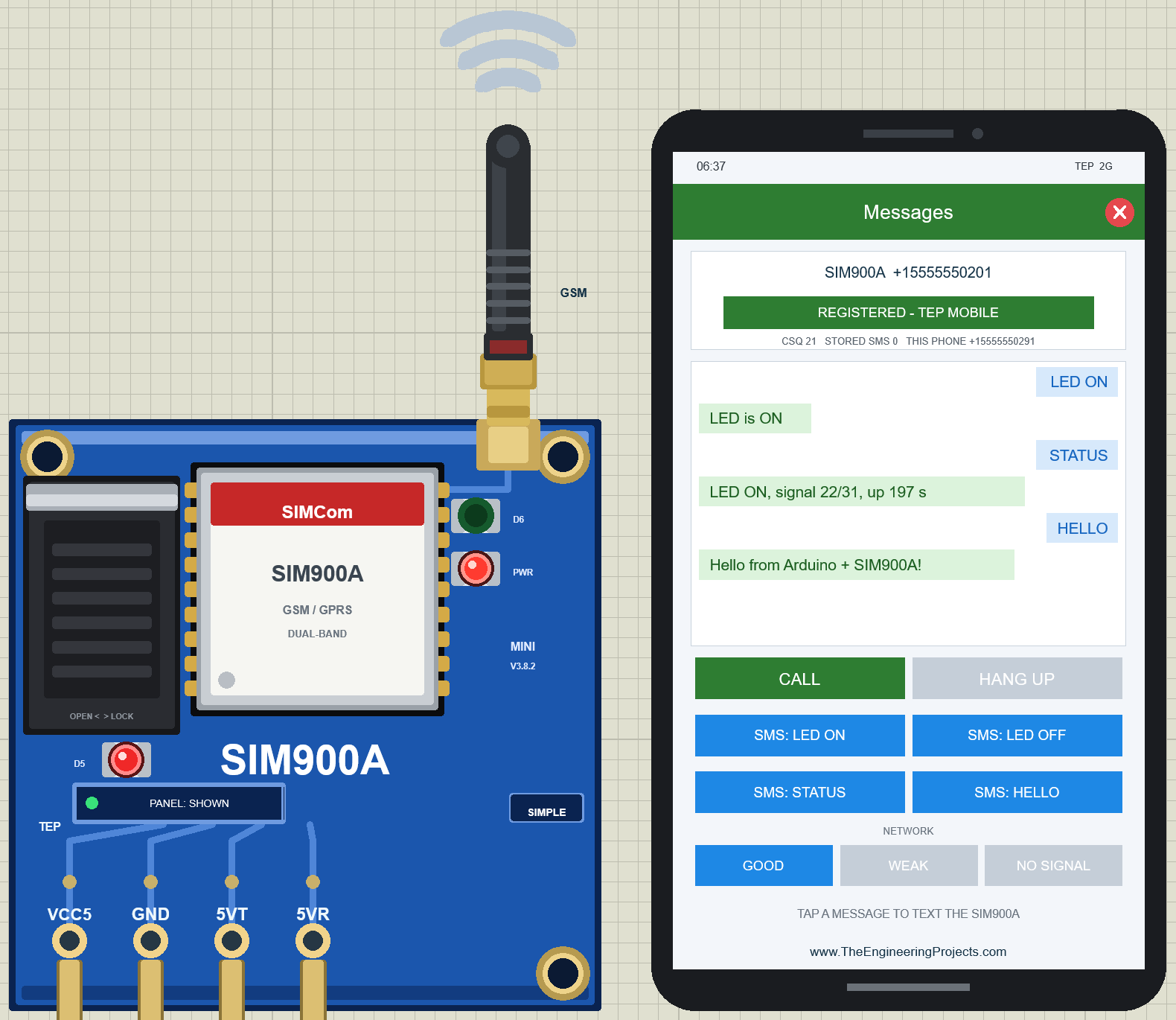
| Part | What it does |
|---|---|
| Status bar | The network time and "TEP 2G" |
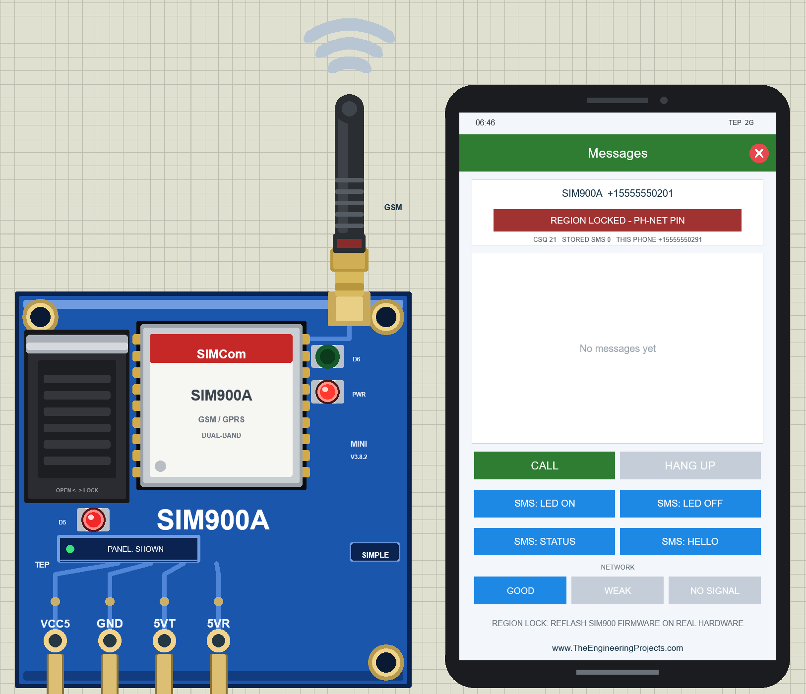
| Module card | The SIM900A's number, its state (for example SEARCHING FOR NETWORK, NO SIGNAL, REGION LOCKED - PH-NET PIN or REGISTERED - TEP MOBILE), CSQ, stored SMS and the phone's own number |
| Conversation | Blue bubbles from the phone, green bubbles from the module, call events in grey |
| CALL / ANSWER | Calls the SIM900A, or answers when the module calls the phone |
| HANG UP | Ends or rejects a call (the module gets NO CARRIER) |
| SMS: LED ON, LED OFF, STATUS, HELLO | Texts the module; it arrives 1.2 - 1.9 s later |
| NETWORK | GOOD, WEAK or NO SIGNAL |
| Tip line and red X | A hint (for example about AT+CMGF=1 or the region lock); the X closes the phone |
Texting the Arduino
Tap SMS: LED ON. 1.2 - 1.9 s later (a little different for every message) the module receives it, the sketch switches LED D1 on, and the reply LED is ON appears as a green bubble. STATUS returns the LED, the signal and the up time ("LED ON, signal 22/31, up 197 s"), and HELLO gets "Hello from Arduino + SIM900A!". The duck's ring and tip light orange while the module sends and green while it receives.
Calling the Module
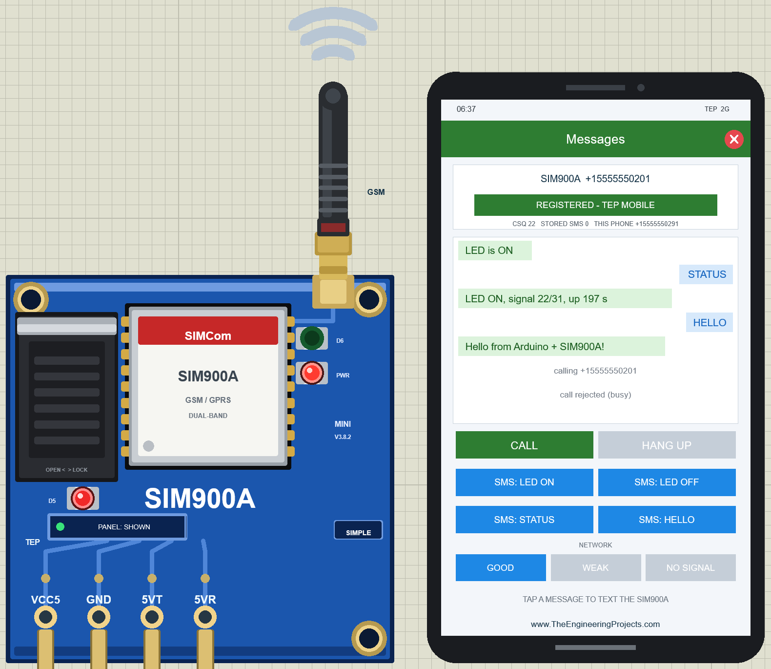
Tap CALL. Two seconds later the module reports RING and the caller's number, and D5 goes dark while RI is LOW. The sketch prints the number and rejects the call with ATH, so the phone shows "calling +15555550201" and "call rejected (busy)":
No Signal and the SMS Centre
Click NO SIGNAL: +CREG: 0,2, D6 blinks fast again, and AT+CSQ answers +CSQ: 0,0, the SIM900A's way of saying "no signal" (a SIM800 says 99,99). An SMS tapped now waits at the SMS centre and is delivered after GOOD. With WEAK (CSQ 7 - 9), every SMS takes 2.5 times as long.
Closing the Phone
Click the red X in the phone's app bar to close it. The board button turns into PANEL: CLOSED, and the module keeps working. Click PANEL to bring the phone back.
SIM900A Advance: The Pop-Up Panel
The Advance device keeps only the board on the sheet and opens a TEP pop-up at Run, with no Windows title bar and the look of our TEP Serial Monitor. Move, resize or minimise it; OPEN PANEL on the board reopens it. The header shows the state (U2 · REGISTERED), the tabs Phone and Test, and the theme, Settings and Help icons; chips below it show the numbers, the operator, the UART speed and the signal.
The Phone Page
Beside the phone, three cards tell you what a real phone never could:
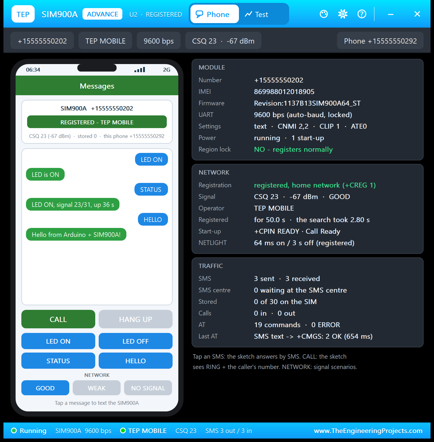
- MODULE: number, IMEI, firmware "Revision:1137B13SIM900A64_ST", UART "9600 bps (auto-baud, locked)", the sketch's settings ("text · CNMI 2,2 · CLIP 1 · ATE0") and Region lock: NO - registers normally.
- NETWORK: +CREG 1, CSQ 23 · -67 dBm, TEP MOBILE, "the search took 2.80 s", start-up "+CPIN READY · Call Ready" and the NETLIGHT pattern.
- TRAFFIC: 3 SMS sent and 3 received, 19 AT commands with 0 ERROR, and the last one: "SMS text -> +CMGS: 2 OK (654 ms)".
654 ms for an SMS? That is not a typo but a SIM900A habit, and the Test page explains it.
The Test Page: GSM Test Tools
The Test page has four tools. Every number is measured on the running model, and your sketch sees everything a tool does.
1. Network: How Long Until the SIM900A is Ready?
Choose Restart or Radio off / on and 3, 5 or 10 runs. Restart switches the module off at once, like AT+CPOWD=0, and the board's held PWRKEY switches it on again 1 s later. Five restarts:
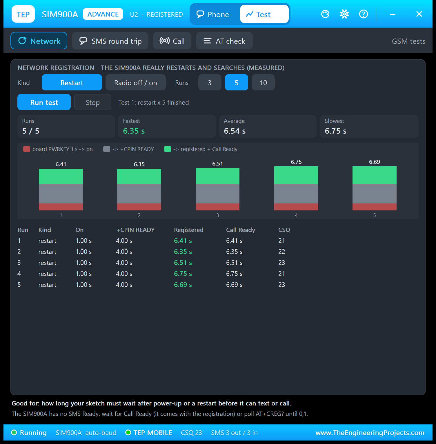
Each bar shows on at 1.00 s, +CPIN READY at 4.00 s and registered at 6.41, 6.35, 6.51, 6.75 and 6.69 s. The Call Ready column has the same times, because the SIM900A sends Call Ready together with the registration (a SIM800 sends Call Ready and SMS Ready before it). So after a power-up, your sketch must wait about 7 s before it can text or call.
A restart also wipes the settings. Watch U4: within 30 s the sketch prints "The SIM900A restarted (settings lost) - setting it up again". Radio off / on (AT+CFUN=0, then AT+CFUN=1) keeps the settings; in our PC tests it registered again after 2.51 - 3.06 s.
2. SMS Round Trip
This tool tests your sketch: the phone texts a command 3, 5 or 10 times, and the sketch's reply stops the clock. STATUS, 5 runs:
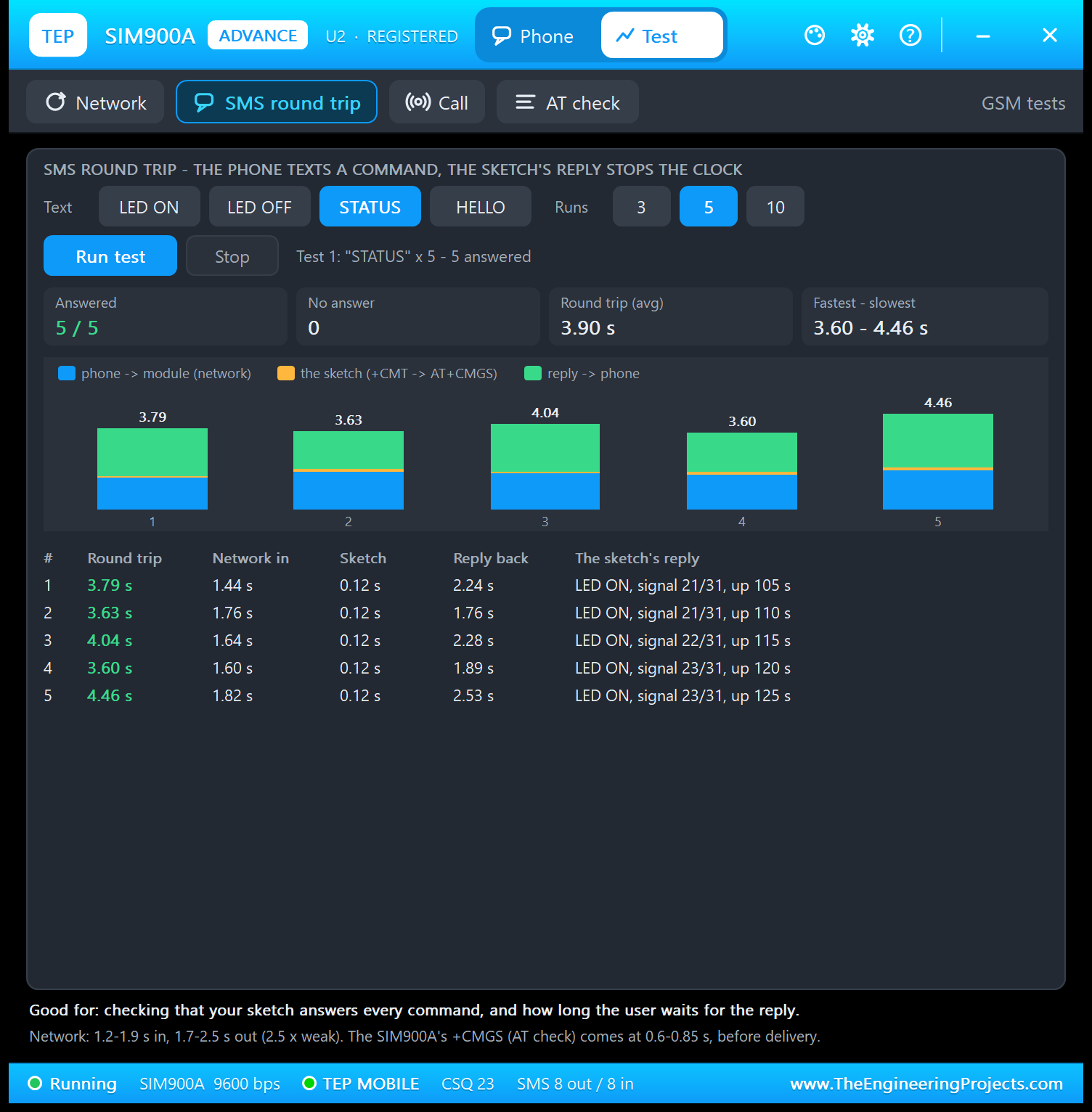
All five were answered, in 3.60 - 4.46 s. Each bar has three legs: network in (1.44 - 1.82 s), the sketch (+CMT to AT+CMGS, 0.12 s every time) and reply back (1.76 - 2.53 s). The network legs change from message to message, like on a real network; your sketch's part does not.
Now compare the reply leg with the 654 ms on the Phone page. The SIM900A answers +CMGS: n as soon as the SMS centre has the message, 0.6 - 0.85 s after Ctrl+Z, while the SMS reaches the phone 1.7 - 2.5 s after Ctrl+Z. A SIM800 answers +CMGS only after delivery. So on a SIM900A, +CMGS means the network accepted your SMS, not that it arrived.
3. Call Test
The phone calls the module 1, 3 or 5 times. The tool records the RINGs, the +CLIP line, the RI signal (LED D5) and whether your sketch answers (ATA) or rejects (ATH). Three calls:
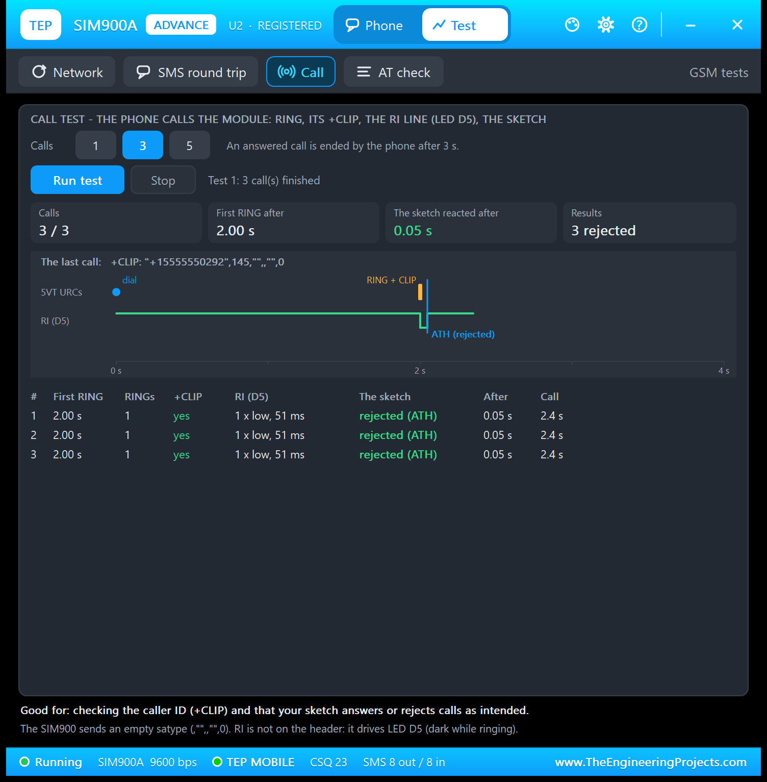
Each call rang 2.00 s after dialling and was rejected 0.05 s after the RING. Above the timeline is the module's own line: +CLIP: "+15555550292",145,"",,"",0. See the double comma? That is the SIM900 format, with an empty field where a SIM800 sends a 0 ("",0,"",0). A parser that expects a number there breaks; our sketch only reads the number between the first quotes.
RI (D5) went LOW once, for 51 ms. RI stays LOW until the call is answered or ended, so the dip shows how fast the sketch hung up. A call nobody answers ends after 30 s with NO CARRIER.
4. AT Check
Twelve read-only queries, answered live by the model, plus the last 8 AT commands from your Arduino with their replies and response times:
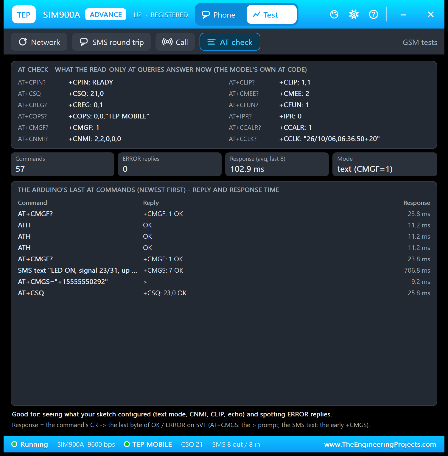
In my run: +CPIN: READY, +CSQ: 21,0, +CREG: 0,1, +CMGF: 1, +CNMI: 2,2,0,0,0, +CLIP: 1,1, +IPR: 0 (auto-baud), +CCALR: 1 and the network clock "26/10/06,06:36:50+20" (+20 = UTC+5, in quarter hours), after 57 commands with 0 ERROR. ATH took 11.2 ms, AT+CSQ 25.8 ms, and the SMS text 706.8 ms to its +CMGS: 7, the early +CMGS again. Good for: checking your set-up code and spotting ERROR replies.
Settings and Help
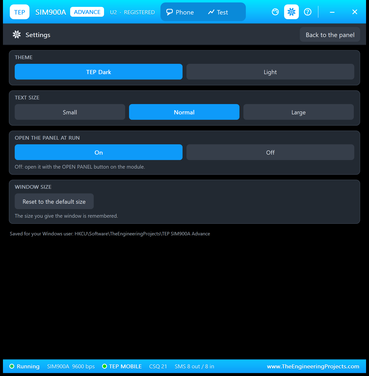
These pages work like in our NEO-6M Library for Proteus and HC-05 Library for Proteus. The gear opens Settings: theme (TEP Dark or Light), text size, open the panel at Run, and a button that resets the window size, all saved for your Windows user.
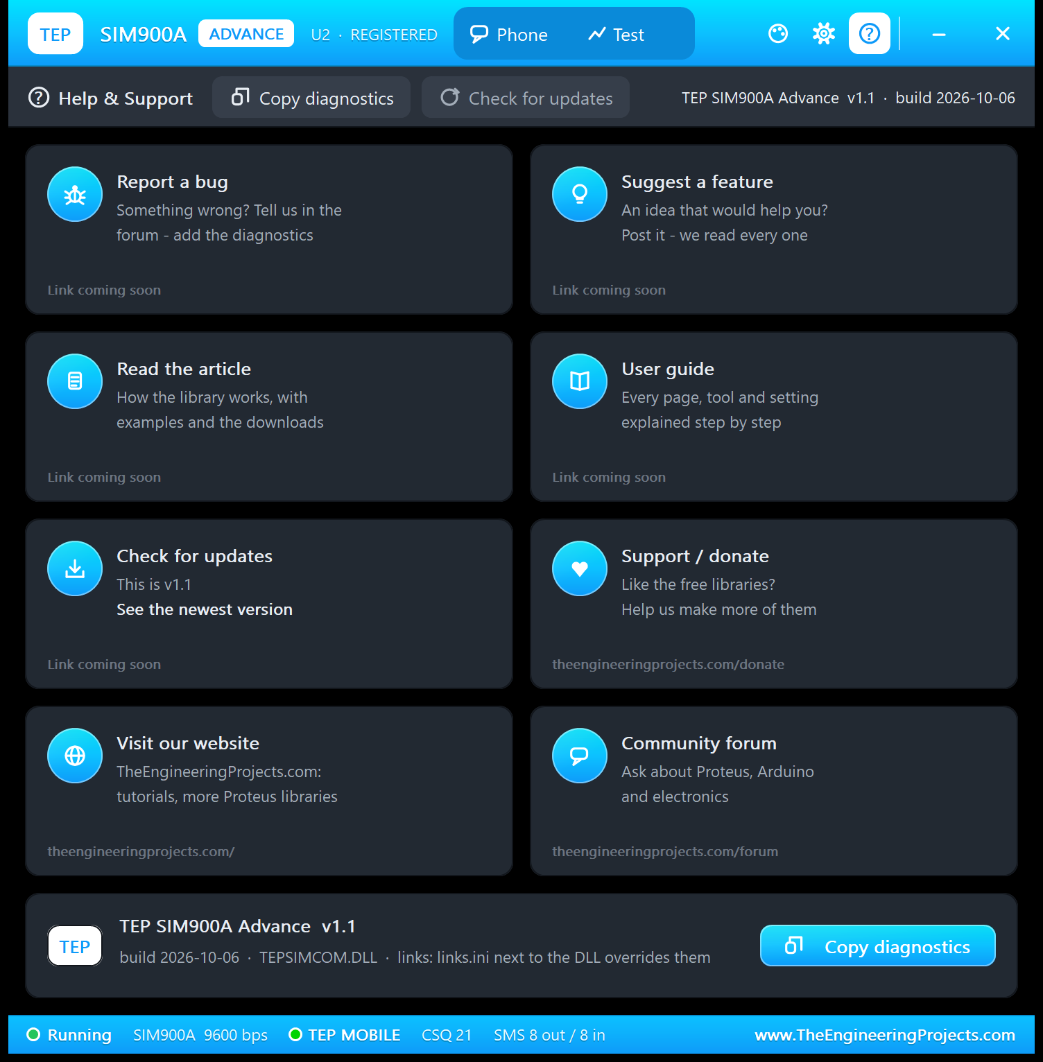
The ? icon opens Help & Support: eight cards (bug report, feature idea, article, user guide, updates, donate, website, forum; unpublished links say "Link coming soon") and Copy diagnostics, which copies the module, network, traffic and test results for a bug report.
Arduino SIM900A Proteus Simulation
Now open the demo, SIM900A-SMS-Control-ArduinoUnoV3.pdsprj in the Proteus Simulation folder. It has two Arduino UNOs from our Arduino Library for Proteus V3.0, both running the same sketch:
- NODE 1: UNO 1 (ARD1) with the SIM900A Simple (U1, +15555550201, its phone +15555550291), LED D1 and Serial Monitor U3.
- NODE 2: UNO 2 (ARD2) with the SIM900A Advance (U2, +15555550202, its phone +15555550292), LED D2 and Serial Monitor U4.
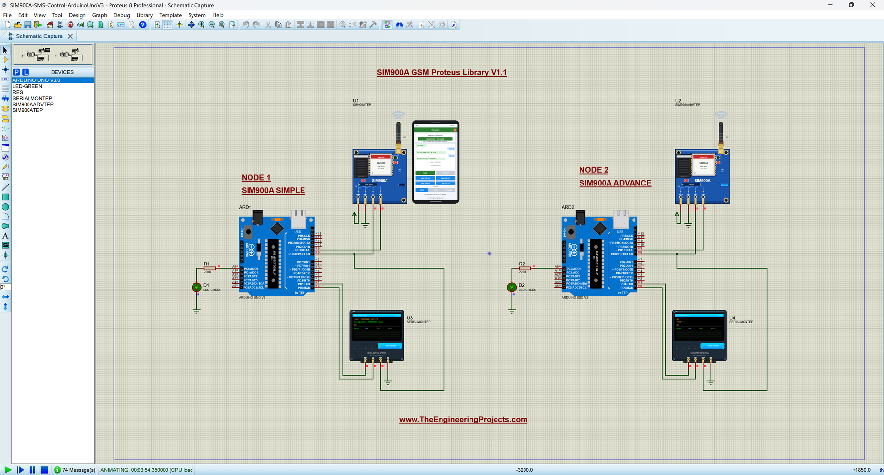
Wiring
| From | To | Why |
|---|---|---|
| SIM900A 5VT | Arduino D8 | AltSoftSerial RX: answers and URCs |
| SIM900A 5VR | Arduino D9 | AltSoftSerial TX: AT commands |
| SIM900A VCC5 / GND | Supply / ground | Power |
| LED + 220 Ω | A0 to GND | The LED switched by SMS |
| Serial Monitor RXD / TXD | Arduino D1 / D0 | Shows what the Arduino prints, sends what you type |
| Serial Monitor RXD2 | The SIM900A's 5VT line (a junction on the 5VT -> D8 wire) | Shows the module's raw replies (BAUD2 9600) |
| Serial Monitor GND | Ground | Common ground |
There is no wire for power-on, reset or RI. The D9 wire crosses the D8 wire without a junction dot, so they are not connected. More about the UNO's pins: Introduction to Arduino UNO.
Why AltSoftSerial?
SoftwareSerial needs pin-change interrupts to receive, and the Proteus 8.5 ATmega328P model never runs them: your sketch would send AT commands but never hear the answers. AltSoftSerial (Paul Stoffregen, MIT licence) uses Timer1, works in Proteus and on real boards, and always uses D8 (RX) and D9 (TX) on the UNO. Don't use D10 while it runs.
The Arduino Code
SIM900A_SMS_Control.ino follows the SIM900A's start-up step by step. First it finds the auto-bauding module: "AT" every half second, a dot for every try:
  Serial.print(F("Waiting for the SIM900A"));
  bool found = false;
  for (byte i = 0; i < 30 && !found; ++i) {
    gsm.print(F("AT\r"));
    found = waitFor("OK", 500);
    if (!found) Serial.print('.');
  }
Then the region lock check. Our PC tests found a race here: the start-up "+CPIN: READY" could be read as the answer to AT+CPIN? and hide the lock, so the sketch lets it pass first:
  // "+CPIN: READY" is also a start-up message (about 3 s after power-on once "AT" has set the baud
  // rate, even on a region-locked module). Let it pass first, so the line read below really is the
  // answer to AT+CPIN?.
  waitFor("+CPIN:", 1500);
  locked = false;
  if (command("AT+CPIN?", "+CPIN:", answer, sizeof(answer)) && strstr(answer, "PH-NET")) {
    locked = true;
    Serial.println(F("REGION LOCK: AT+CPIN? -> +CPIN: PH-NET PIN"));
Next it waits for Call Ready, not SMS Ready. After a reset of the UNO alone, AT+CCALR? tells whether Call Ready has already passed:
    Serial.print(F("Waiting for Call Ready (sent after network registration)... "));
    // AT+CCALR? answers "+CCALR: 1" if Call Ready came before this sketch started (a reset of the UNO)
    bool ready = command("AT+CCALR?", "+CCALR:", answer, sizeof(answer)) && answer[8] == '1';
    if (!ready) ready = callReady || waitFor("Call Ready", 20000);
Then it sets up text-mode SMS and caller ID:
  command("ATE0");                     // no echo
  command("AT+CMEE=2");                // errors as text
  command("AT+CMGF=1");                // SMS in text mode
  command("AT+CNMI=2,2,0,0,0");        // print new SMS directly (+CMT:)
  command("AT+CLIP=1");                // show the caller's number (+CLIP:)
For a call, it copies the number between the first quotes, so the SIM900's empty +CLIP field does no harm:
  } else if (!strncmp(s, "+CLIP:", 6)) {
    quoted(s, caller, sizeof(caller));   // "+CLIP: "+15555550291",145,"",,"",0"
    callWaiting = true;
Replies go out with AT+CMGS, the "> " prompt and Ctrl+Z. On a SIM900A, the wait for +CMGS ends after about 0.7 s:
  gsm.write(26);                       // Ctrl+Z sends the message
  return waitFor("+CMGS:", 30000) && waitFor("OK", 2000);
The signal function knows the SIM900's "no signal" answer:
return atoi(answer + 6); // "+CSQ: 22,0" -> 22 (0..31; the SIM900 reports 0,0 without network)And every 30 s, AT+CMGF? checks that the module still remembers text mode; after a restart, the sketch sets it up again:
  // every 30 s: is the module still set up? (a restart / brown-out clears its settings)
  if (restarted || millis() - lastCheck > CHECK_EVERY) {
If you change the sketch, load the new HEX file into both UNOs; see How to get the HEX file from Arduino. New to Arduino? Start with our Arduino Tutorial for Beginners.
Serial Monitor Commands
| Command | What it does |
|---|---|
| AT... | Sent to the SIM900A as typed; the answer lines are printed with " < " until OK or ERROR (3 s). Try AT+CPIN? or AT+CCALR?. |
| STATUS | LED, signal (CSQ), registered or not (and "region lock" if that is the reason), operator, up time |
| TEXT <message> | An SMS to the last number that texted the module (text it first) |
| HELP | The command list |
In the full interface, each monitor also has four quick buttons: AT+CSQ, AT+CREG?, STATUS and TEXT Hello from Arduino.
How to Run the Demo
- Open the project (keep the .hex file and both DLLs beside it) and press Run. Both Serial Monitors open at 9600 baud, and so does U2's pop-up.
- After about 8 s of simulation time, both monitors show the command list.
- On U1's phone, tap SMS: LED ON and watch D1 and U3. Then tap CALL and watch D5.
- In U2's pop-up, run the four test tools while you watch U4.
- Finally, stop, set REGIONLOCK = YES on U1 and run again (see the region lock section).
Simulation Results in the TEP Serial Monitor
Our demo uses the TEP Serial Monitor Advance for Proteus instead of Proteus's Virtual Terminal. In every screenshot of this article, both monitors are in their Simple interface, and I suggest you try it too.
The Simple Interface
The Simple interface keeps only the log, the send box and one slim toolbar row with the baud rate, follow (auto-scroll), pause, search and clear buttons. The header, the quick-send row and the status bar are hidden, so the window stays small next to your schematic. To switch to it, right-click the log and choose Simple interface, or press Ctrl+Shift+U. To get the full view back, click the corner button (the expand arrows at the top right), press Esc or Ctrl+Shift+U, or right-click and choose Full interface. The monitor remembers your choice. Need the quick buttons? Switch to the full view, or just type the command.
Two Inputs: RX and RX2
Each monitor has a second serial input, RXD2. In this demo it listens to the module's 5VT line, so the log mixes two sources: green RX lines are what the sketch prints, and amber RX2 lines are the module's raw replies. You see the AT conversation from both sides at once.
Some RX2 rows look empty. That is not a bug: the SIM900A starts and ends every reply with a CR LF line end, so an empty row appears between, for example, +CMGS: 2 and OK. Until the sketch sends ATE0, the module also echoes every command back in amber.
After Run, each monitor shows the start-up (this is the README's listing; the time comes from the network clock):
SIM900A SMS remote control v1.1
www.TheEngineeringProjects.com
Waiting for the SIM900A.......
SIM900A found
Model:    SIMCOM_SIM900A
Firmware: 1137B13SIM900A64_ST
Waiting for Call Ready (sent after network registration)... ok
Waiting for the network... registered
Signal:   CSQ 22 (good)
Operator: TEP MOBILE
Time:     26/09/30,12:00:07+20
Ready - SMS commands: LED ON, LED OFF, STATUS, HELLO
Serial Monitor: AT... (to the SIM900A), STATUS, TEXT <message>, HELP
An SMS in the Log
Here is U4 when the phone in U2's pop-up texted HELLO:
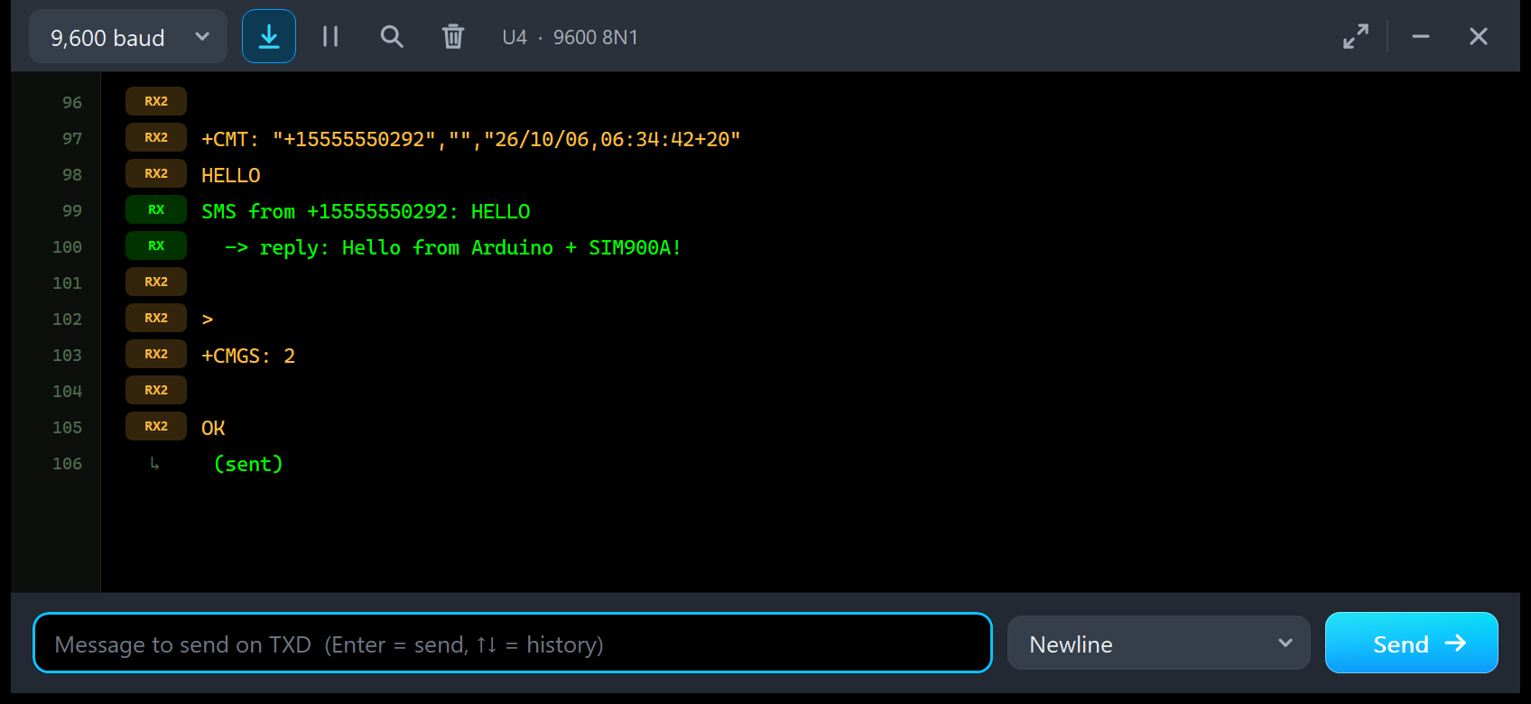
The module reports +CMT: "+15555550292","","26/10/06,06:34:42+20" and the text HELLO (amber). The sketch prints "SMS from +15555550292: HELLO" and its reply (green). The module answers AT+CMGS with the ">" prompt, +CMGS: 2 and OK, and the sketch's " (sent)" lands on its own row with a small arrow, because the module's lines came in between.
A Call in the Log
And this is U3 when I tapped CALL on U1's phone:
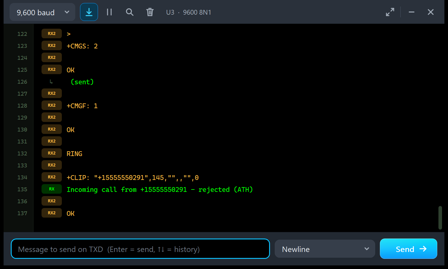
After the sketch's 30-second check (+CMGF: 1, OK) come RING, the SIM900 +CLIP line with its empty field, the green "Incoming call from +15555550291 - rejected (ATH)" and the OK for ATH. With RX2, you never have to guess what the module really said.
The SIM900A Region Lock in Proteus
What is the Region Lock?
This is the story behind the SIM900A's bad reputation. From build 1137B06SIM900A32_ST on, stock SIM900A firmware only works in a list of Asian countries: China, India, Singapore, Malaysia, Thailand, Indonesia, Cambodia, Vietnam, Laos, Burma, Brunei, the Philippines and East Timor. Pakistan, for example, is not on it. Outside the list, the module:
- still reports +CPIN: READY at start-up, so everything looks fine,
- but answers
AT+CPIN?with +CPIN: PH-NET PIN: the SIM is fine, the network is not allowed, - never registers (+CREG: 2 for 4 s, then +CREG: 0 for 26 s, again and again), so D6 keeps blinking about once a second and Call Ready never comes,
- still reports a signal with AT+CSQ and lists the operator with AT+COPS=?, but selecting it answers ERROR.
So people see a good signal and spend days checking their wiring, when the real problem is the firmware.
Switching the Lock On: REGIONLOCK = YES
Our model reproduces these symptoms with one property. Stop the simulation, double-click U1, set REGIONLOCK to YES and press Run. The phone's state turns red, REGION LOCKED - PH-NET PIN, the tip line says "REGION LOCK: REFLASH SIM900 FIRMWARE ON REAL HARDWARE", and no message ever arrives, although the signal is good (CSQ 21):
What the Arduino Sees
The demo sketch detects the lock and explains it. In a long log, the quickest way to find the message is the monitor's search: click the magnifier and type "REGION LOCK:". The monitor jumps to the match, highlights it in yellow and shows "1 of 1"; the arrows step between matches, and a blue button ("141 more lines") jumps back to the newest line:
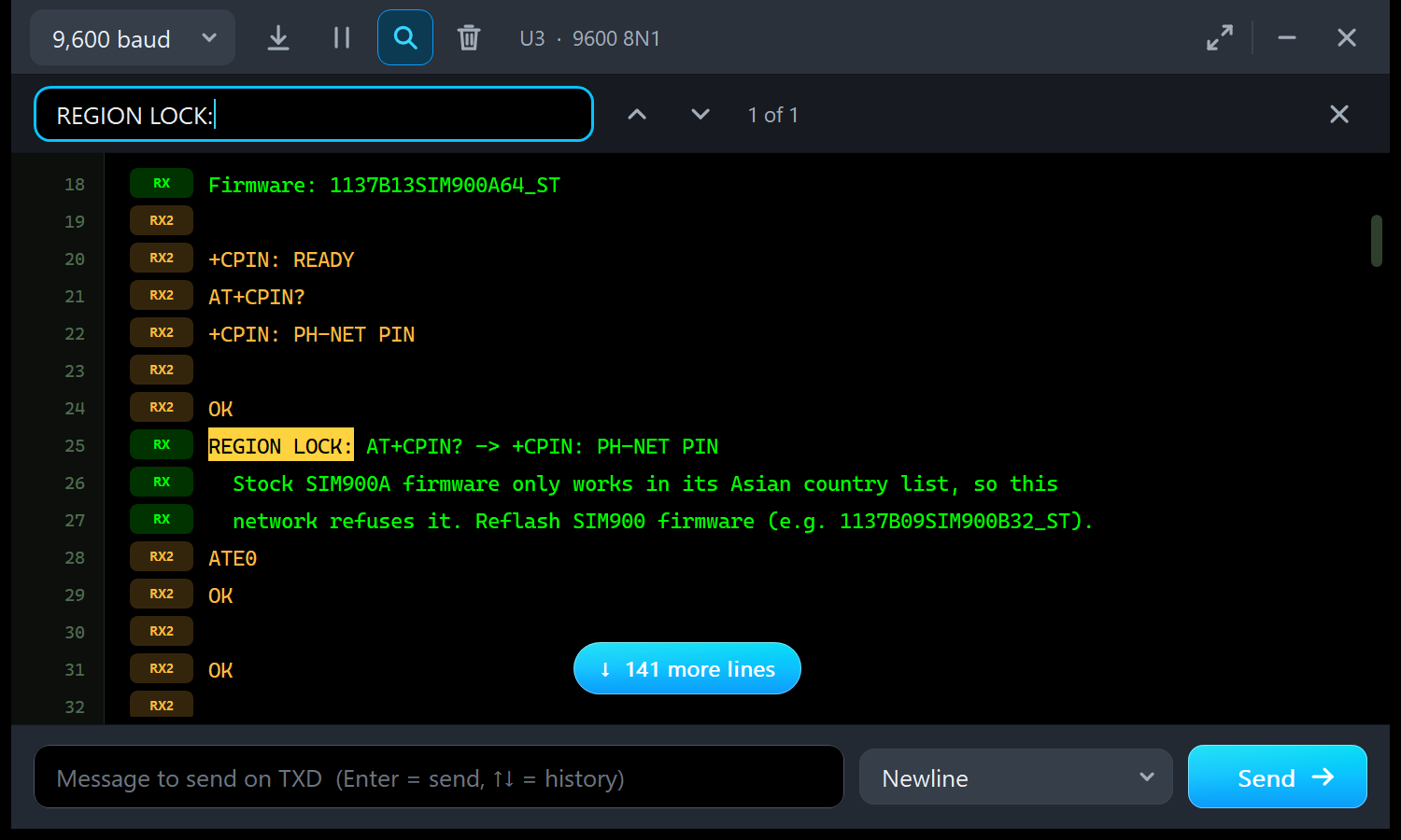
In amber, the module sends +CPIN: READY at start-up, then the echo of AT+CPIN? and the answer +CPIN: PH-NET PIN. In green, the sketch prints:
REGION LOCK: AT+CPIN? -> +CPIN: PH-NET PIN
  Stock SIM900A firmware only works in its Asian country list, so this
  network refuses it. Reflash SIM900 firmware (e.g. 1137B09SIM900B32_ST).
It then waits about 30 s for the network and ends its start-up with "Region locked - SMS and calls will not work on this network". STATUS also says "NOT registered (region lock)".
The Region Lock in the Advance Pop-Up
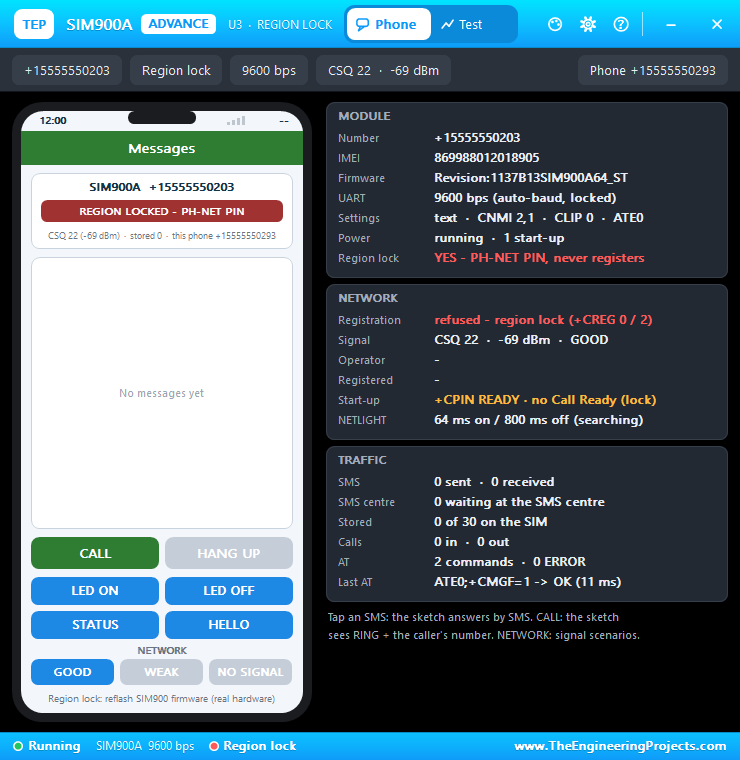
On an Advance module, the pop-up shows the lock everywhere: the MODULE card says "YES - PH-NET PIN, never registers" in red, the NETWORK card "refused - region lock (+CREG 0 / 2)" and "+CPIN READY · no Call Ready (lock)", and the AT check shows +CPIN: PH-NET PIN in red:
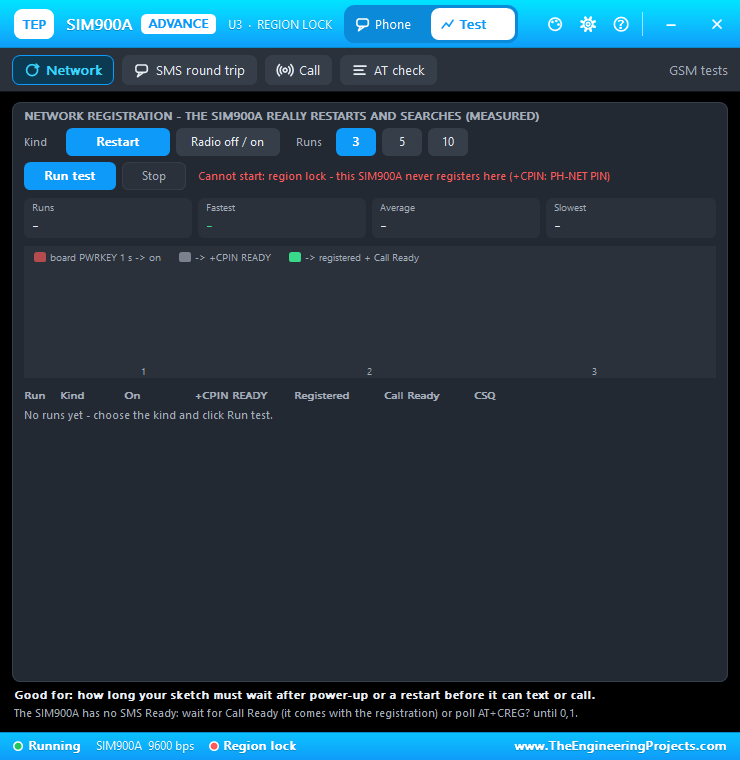
The Network test refuses to start, because a locked module would never finish a single run:
How to Fix It on a Real Module
Flash SIM900 firmware into the module, for example 1137B09SIM900B32_ST for 32 Mbit flash or a 1137B0xSIM900M64_ST build for 64 Mbit, with SIMCom's "SIM900 Series download Tools". Afterwards, AT+CGMM answers SIMCOM_SIM900. Not every board is locked: it depends on the firmware build and the country's network code, and boards with older or reflashed firmware work. That is why REGIONLOCK defaults to NO, an unlocked module.
SIM900A AT Commands Supported
| Group | Commands |
|---|---|
| General | AT, ATE0/1, ATI (SIM900 R11.0), ATV, ATQ, ATZ, AT&W, AT&V, ATS<n>, AT+CGMI, +CGMM (SIMCOM_SIM900A), +CGMR, +GSV, +CGSN, +CCID, +CIMI, +CPIN?, +CFUN (0, 1, 4; 1,1 restarts), +CPOWD (1 = NORMAL POWER DOWN, 0 = urgent off), +CPAS, +CBC, +CCLK, +CLTS, +CIURC, +CCALR?, +CBAND, +CMEE, +IPR; several commands on one line |
| Network | AT+CREG (0 / 1 / 2), +CSQ (AT+CSQ? is ERROR, as the manual says), +COPS? / =?, +CGATT?, +CUSD=1,"*123#" (balance message) |
| SMS (text mode) | AT+CMGF=1, +CSCS, +CSCA?, +CNMI=2,1 (+CMTI) or 2,2 (+CMT), +CMGS with the "> " prompt, Ctrl+Z / ESC, +CMGR, +CMGL, +CMGD, +CMGDA, +CPMS (30 messages) |
| Calls | ATD+number;, ATA, ATH, AT+CLIP=1 (RING + +CLIP every 3 s), AT+CLCC |
| Unknown | ERROR, and the command is named in the Simulation Log |
Without network, AT+CMGS fails after 2 s (ERROR, or +CMS ERROR: 331 with AT+CMEE=1). An SMS sent to a module that is off or not registered waits at the SMS centre until it registers.
Troubleshooting
- "No answer from the SIM900A": check 5VT -> D8 and 5VR <- D9. The serial port works about 3 s after power-up, and the module learns the speed only from "AT" or "At" (upper-case A).
- The sketch waits forever for "SMS Ready": the SIM900A has none. Wait for Call Ready or ask AT+CCALR?.
- It never registers / +CPIN: PH-NET PIN: REGIONLOCK is YES.
- SMS arrive but the sketch sees nothing: send
AT+CMGF=1andAT+CNMI=2,2,0,0,0. - No answers after a restart (Network test, AT+CFUN=1,1, AT+CPOWD=1): the module auto-bauds again and has lost its settings. Send "AT" and set it up again.
- Garbage characters at power-up: the sync bytes, sent at 115200 bps. Normal.
- The Test tab says "Cannot start": the message gives the reason (no power, region lock, another test, a call in progress).
- No phone, pop-up or monitor:
TEPSIMCOM.DLLorTEPSERIALMON.DLLis missing from MODELS and the project folder. Click OPEN PANEL or OPEN MONITOR on the part to reopen a closed window. - The red X does not close the phone: the design still holds the v1.0 symbol; replace the LIB, delete TEPSIM900A.IDX and re-pick the part.
Things to Know Before Using a Real SIM900A
- Power: the module draws up to 2 A in its transmit bursts. Feed VCC5 from a 5 V supply that can deliver 2 A peaks (sellers ask for "5V DC above 1A"), not the Arduino's 5V pin, with a common GND.
- Logic levels: 5VT / 5VR for a 5 V Arduino such as the UNO (no divider needed), 3VT / 3VR for a 3.3 V board.
- Never put 5 V on VCC4: it is the direct battery input (3.5 - 4.5 V); 5 V shuts the module down with an over-voltage error.
- 2G only: dual-band 900 / 1800 MHz; it does not work where the 2G network is switched off.
- Region lock: before you blame your wiring, check AT+CGMR and AT+CPIN?.
- Patience: on a poor network, a real module can take much longer to send Call Ready.
Limitations of the Simulation
- Not modelled: GPRS / TCP / HTTP / FTP / email, PDU-mode SMS (+CMS ERROR: 304 with AT+CMEE=1), audio, DTMF, the SIM phone book, voltage and temperature warnings, supply current and brown-outs, a missing SIM, DTR and sleep modes, and the pins 3VT / 3VR, VCC4 and VCC_MCU.
- Assumed, because no capture of a real module was found: the ATI text, AT+CBAND? = EGSM_DCS_MODE, the +CLCC line while ringing and the start-up timing.
- The region lock is modelled by its symptoms; the network, operator, SMS centre and USSD reply are simulated, and no real SIM is involved.
- Modules from our SIM800L Library for Proteus use a separate model and network, so they cannot reach these modules.
- Tested in Proteus 8.5 on 6 Oct 2026 (the demo and every Proteus screenshot here, including REGIONLOCK = YES) and with 1,667 automatic checks on the PC; Proteus 7 is not supported.
Want to compare SIMCom modules? Our SIM800C Library for Proteus uses the same model file, and our SIM800L Library for Proteus has the small red SIM800L. Need GPS too? Try our SIM808 Library for Proteus. For Wi-Fi instead of GSM, see our ESP-01 Library for Proteus.
So, that was all about the new SIM900A Library for Proteus (V1.1). I hope the virtual phone, the test tools and especially the region lock save you a lot of time with your GSM projects, in Proteus and on the real board. Please share your feedback in the comments or in our forum, and if you have any questions, ask in the comments and I will help you out. Till the next tutorial, take care and have fun!