Hello friends, I hope you all are doing great. Today, I am going to share the new 1N4007 Diode Library for Proteus. If there is one diode everybody knows, it is this little black cylinder with a silver band. It is in phone chargers, power supplies and relay boards, and it costs next to nothing. It does one simple thing very well: it lets current flow one way, and stops it flowing back.
1N4007 Diode Library for Proteus
Latest version: V1.0 (November 2026, this tutorial)
Other component libraries: C945 Transistor · PC817 Optocoupler · Relay Module · Resistor · 5 mm LED · Designer Colour LED · Push Button · Active Buzzer · Electrolytic Capacitor · Ceramic Capacitor · Tantalum Capacitor · Film Capacitor · Zener Diode · Schottky Diode · Supercapacitor · Photodiode · RGB LED · Bridge Rectifier · Flashing LED · Bi-Colour LED · SMD LED · Slide Switch · Toggle Switch · Rocker Switch · Micro Limit Switch · Emergency Stop Switch · SMD Resistor · Power Resistor · Resistor Network · Potentiometer · Trimmer Potentiometer · Slide Potentiometer · NTC Thermistor · DIP Switch · Fuse · Passive Buzzer · Mini Speaker · 7-Segment Display · LED Bar Graph · IR / UV LED · Small Transistors · TIP122 Darlington · N-MOSFET · P-MOSFET · PC817 Optocoupler · Filament Bulb · Power LED · Voltage Regulator · SCR and TRIAC · Inductor · Toroid Inductor · Crystal
Helping Tools
- Serial Monitor Advance: a serial terminal window for the UART of your board
- Serial Monitor Expert: the serial monitor with extra debugging tools
- LCD Library for Proteus V3.0: 16x2, 20x4 and I2C LCDs to show your readings
Proteus has a diode, of course, drawn as a triangle and a bar. Ours is the real part, at true scale, and it is alive. Beads of current run along its legs when it conducts, and its band warns you when it is blocking. Click it at Run and the pop-up draws its curve with a dot on the exact point where it is working right now, which is the clearest way I know to understand a diode.
NOTICE: Our team has put a lot of effort into these small parts: the bodies, the animation and the pop-ups are all our own design, and you get them free. Your feedback is the fuel that keeps us going, so please tell us what you think in the comments below or in the 1N4007 Diode board of our forum. And if our free libraries help you, you can buy us a coffee. So, let's get started with the 1N4007 Diode Library for Proteus:
What is a Diode?
A diode is a one-way valve for electric current. It is made from a single small piece of silicon, doped so that one side has spare electrons and the other side has room for them. Where the two sides meet there is a PN junction. Push current from the anode to the cathode and the junction lets it through, once the voltage has climbed over its small barrier. Push the other way, and the junction closes up and almost nothing flows.
The 1N4007 is the top of the 1N400x family. All seven parts look the same, and they differ mainly in how much reverse voltage they can block, from 50 V for the 1N4001 up to 1000 V for the 1N4007. Since the price is nearly the same, most people simply buy the 1N4007.
| Feature | The real part | In the library |
|---|---|---|
| Body | DO-41, 5.2 x 2.7 mm | 218 x 113 thou, true scale |
| Reverse voltage | 1000 V | 1000 V |
| Forward current | 1 A on average | the Check page warns over it |
| Forward drop | about 0.7 V at small currents | the same, from the diode law |
| Cathode | the silver band | the same |
| Part | Reverse voltage |
|---|---|
| 1N4001 | 50 V |
| 1N4002 | 100 V |
| 1N4003 | 200 V |
| 1N4004 | 400 V |
| 1N4005 | 600 V |
| 1N4006 | 800 V |
| 1N4007 | 1000 V |
Which Way Round?
The band marks the cathode. Conventional current flows from the anode to the cathode, so the band is the side the current comes out of. In the circuit symbol, the bar at the tip of the triangle is the band. A simple way to remember it: the arrow in the symbol points the way the current can go.
The 0.7 V Drop
A diode is not a perfect valve. It takes a certain voltage to push current through the junction, and that voltage is lost. For silicon, it is about 0.7 V. So if you feed a circuit from 5 V through a diode, the circuit only sees about 4.3 V. It is not a fixed number, though. It grows slowly as the current grows, to about 1 V at the full 1 A, and that is exactly what the curve in our pop-up shows.
That drop also means heat. The power lost in the diode is the drop times the current, so at 1 A it wastes about 1 W. That is why the part gets warm in a power supply, and why it can fail if you ask too much of it.
What Does a Rectifier Do?
Mains electricity is AC: it swings positive and negative many times a second. Electronics need steady DC. A rectifier turns one into the other, and the simplest version is one diode. It passes the positive half of each cycle and blocks the negative half. A capacitor after it holds the voltage up during the gaps. That is called a half-wave rectifier, and it is what our demo builds. It is why you will find this part at the input of nearly every mains power supply, though usually four of them, in a bridge.
Flyback Diodes
Here is another job you will meet very soon if you drive relays or motors. A coil hates having its current stopped. When a transistor switches a coil off, the coil throws out a big voltage spike, easily enough to kill the transistor. A 1N4007 placed backwards across the coil gives that current a safe path to die away, and the spike never happens. Nearly every relay board you have seen has one.
Reverse Polarity Protection
Connect a battery the wrong way round to most circuits, and something expensive dies. A single diode in series with the supply prevents that. If the battery is correct, current flows and you lose 0.7 V. If it is reversed, the diode blocks and nothing happens. Many products also use a diode the other way, across the input with a fuse in front of it: when the supply is reversed, the diode conducts hard and blows the fuse. That costs no voltage in normal use.
Reading a Diode With a Multimeter
Most multimeters have a diode setting, marked with the same symbol. Put the red lead on the anode and the black lead on the cathode, and a good silicon diode reads about 0.5 to 0.7 V. Swap the leads and it reads as open. If it shows nearly zero both ways, the diode has failed short. If it reads open both ways, it has failed open. This two-second test finds a great many faults on a real board.
How a Diode Is Marked
Across a family of parts, you will see the same layout: a band at one end, and the part number printed along the body. Some small signal diodes, such as the 1N4148, come in a glass case with a black band, and larger power diodes may have the symbol printed on them. In every case, the band marks the cathode. On a surface-mount part, look for a line on the top of the case.
Diodes in Series and Parallel
You may be tempted to wire two diodes together to get more. In series, they block twice the voltage, though in a real design each needs a resistor across it to share that voltage fairly. In parallel, they do not share the current well: the one with the slightly lower drop takes more, warms up, and takes more again. So choose one larger diode instead. A series string does have one neat use: each diode drops about 0.7 V, so a few in a row can trim a supply down a little without a regulator.
Features of the 1N4007 Diode Library for Proteus
- The real look, at true scale: the black body, the silver band and two thin legs, printed 1N4007, with our small TEP signature.
- Beads of current: small blue beads run along the legs while it conducts.
- A band that warns: it turns green while conducting, and orange while blocking.
- A true diode: the diode law with a series resistance, a tiny leakage, and breakdown past its rating.
- A live curve: the pop-up draws the V-I curve, with a dot on the working point.
- It fails like the real thing: too much power cooks it, and it fails short.
- A complete package: about 2.1 MB with the library, our Arduino UNO V4.0, the demo's resistors, LEDs and capacitor and the demo, without the source code of the models.
The 1N4007 Diode in Proteus
The device is DIODE1N4007TEP in TEP1N4007.LIB, under Diodes, Rectifiers, with the prefix D and the model TEP1N4007.DLL. Search 1N4007 in Pick Devices and look for the TEP name. The pins are A on the left and K on the right, on the band side. There are no properties to set: it is a 1N4007.
Download 1N4007 Diode Library for Proteus
Click the button below to download 1N4007-Diode-Library-for-Proteus-v1.0.zip (about 2.1 MB, without the source code of the models):
1N4007 Diode Library for Proteus V1.0- README.txt: installation, the demo, troubleshooting and the limits.
- Proteus Library Files:
TEP1N4007.LIB,TEPRESISTOR.LIB,TEPLED5MM.LIB,TEPELECTRO.LIBand ourArduinoV4TEP.LIB. - Proteus Model Files:
TEP1N4007.DLL,TEPRESISTOR.DLL,TEPLED5MM.DLL,TEPELECTRO.DLLandTEPARDUINO.DLL. - Arduino Code: the demo sketch.
- Proteus Simulation: the demo project, its HEX file and copies of the DLLs.
No Proteus yet? Read How to Download and Install Proteus 7 and 8. New to libraries? Follow How to Install a New Library in Proteus.
How to Install 1N4007 Diode Library for Proteus
- Close Proteus and extract the whole zip file, for example to your Desktop.
- Copy the files from Proteus Library Files into the LIBRARY folder of Proteus.
- Copy the files from Proteus Model Files into the MODELS folder.
- Delete
TEP1N4007.IDXfrom the LIBRARY folder if it is there. - Start Proteus, press P and search for 1N4007.
Demo: A One-Way Valve and a Rectifier
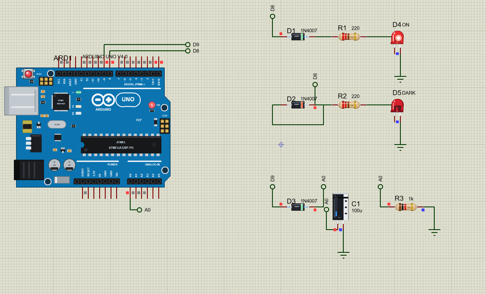
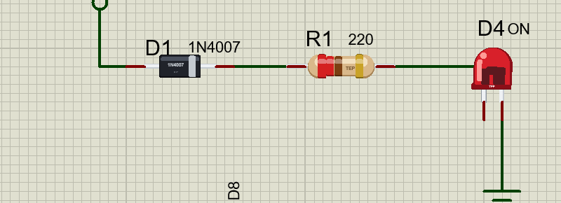
The demo shows both jobs of a diode on one sheet. In the top half, D8 feeds two LEDs through a diode each. D1 points the right way, so LED D4 lights. D2 points the wrong way, so LED D5 stays dark. In the bottom half, D9 makes a square wave, and D3 rectifies it into DC on A0. Open 1N4007-Rectifier-ArduinoUnoV4.pdsprj. It runs on our Arduino UNO Library for Proteus V4.0, with its built-in monitor, the same window as our TEP Serial Monitor Advance for Proteus. The resistors are from our Resistor Library for Proteus, the LEDs from our 5 mm LED Library for Proteus, and the capacitor from our Electrolytic Capacitor Library for Proteus.
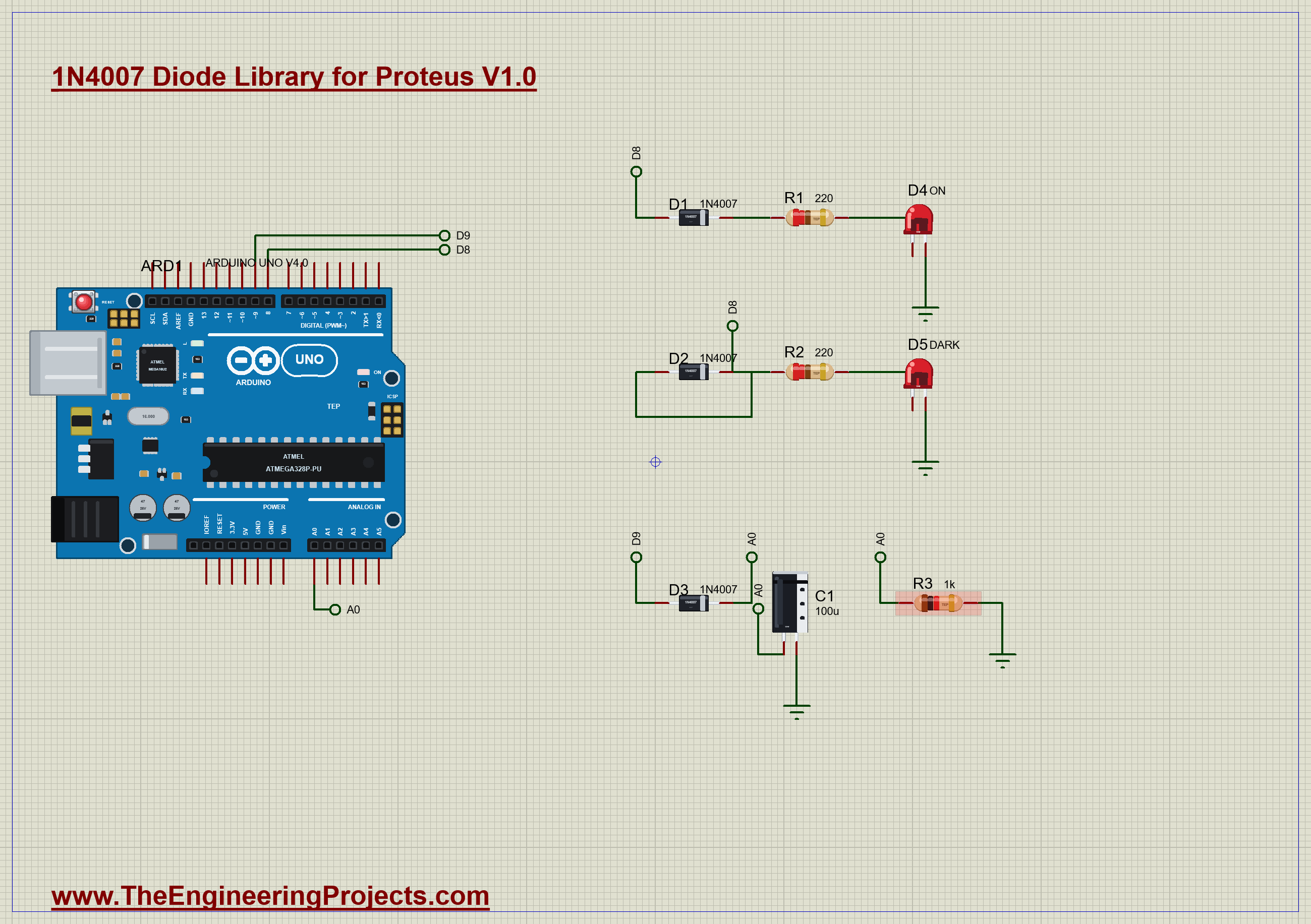
| Part | Connection | Job |
|---|---|---|
| D1, R1, D4 | D8, A to K, then 220 ohm and an LED | the valve, open |
| D2, R2, D5 | D8, K to A, then 220 ohm and an LED | the valve, shut |
| D3 | D9 to A0 | the rectifier |
| C1, 100 uF | A0 to GND | holds the voltage up |
| R3, 1k | A0 to GND | the load |
The Sketch
The sketch sets D8 HIGH and starts a square wave on D9 with analogWrite(), which switches the pin about 490 times a second. Each second it measures A0 with 64 quick readings, and works out the average and the ripple:
  float volts = sum * VCC / SAMPLES / 1023.0;
  Serial.print(F("Output "));
  Serial.print(volts, 2);
The Commands
| Type this | What happens |
|---|---|
| on | the square wave runs |
| off | the square wave stops, and C1 drains through R3 |
Run the Demo
Press Run. D4 lights at once, and D5 stays dark, though both are fed from the same pin. Here is the complete circuit, truly running:
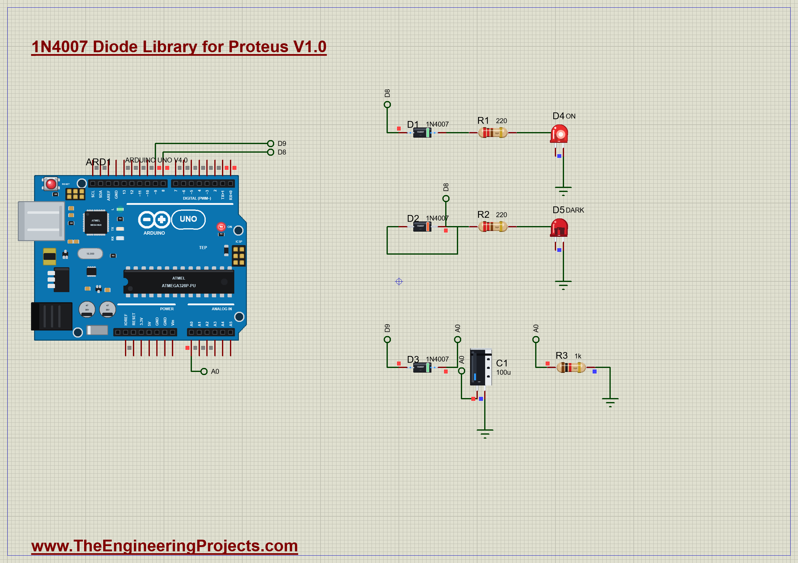
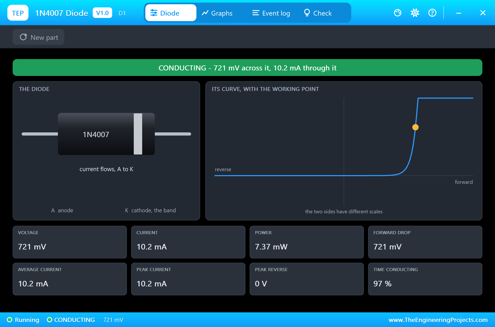
The Open Valve
Click D1 to open its pop-up. The banner says CONDUCTING, the amber dot sits high on the forward side of the curve, and the tile shows the drop:
The Shut Valve
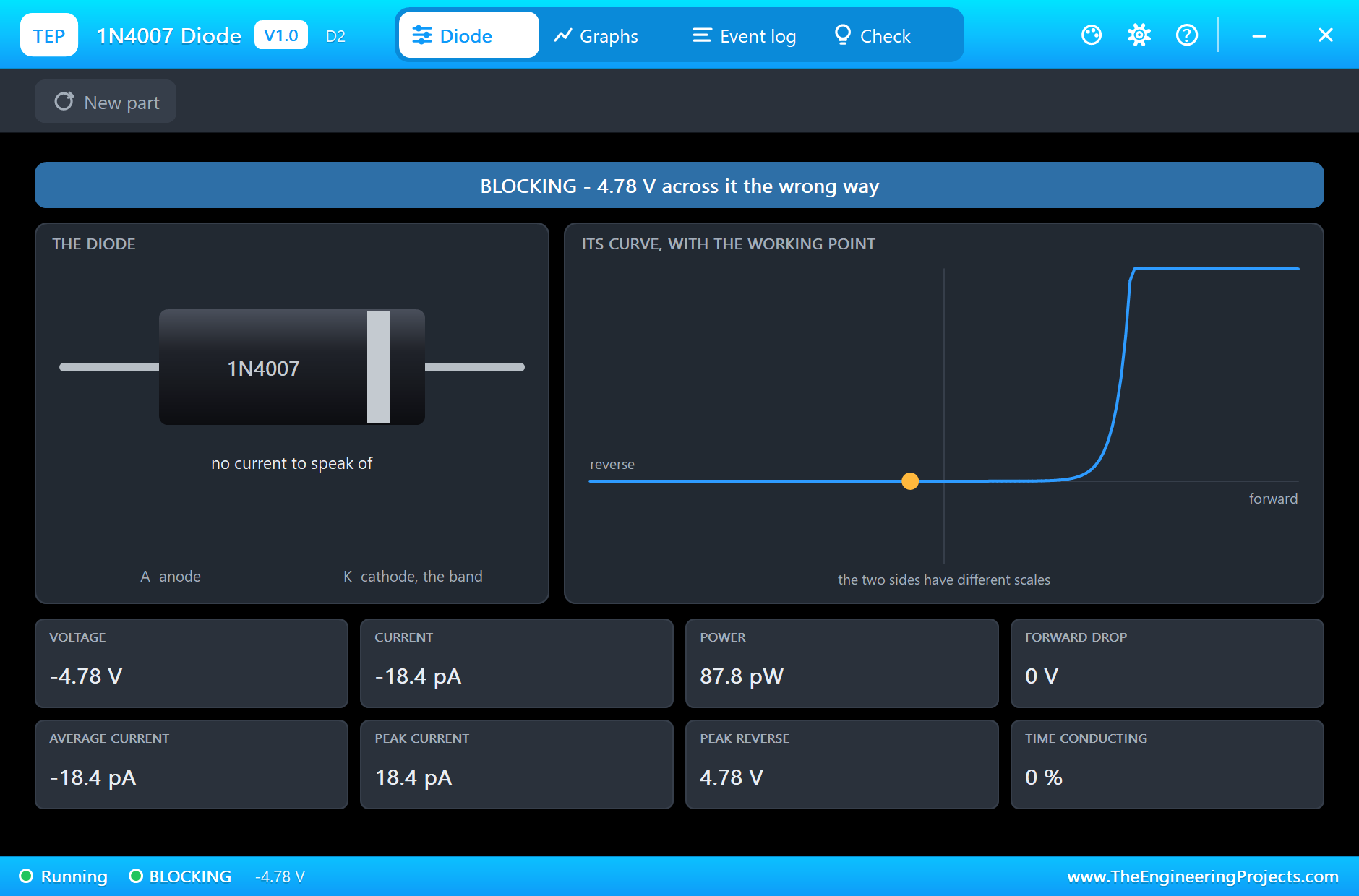
Now click D2. The same 5 V is there, but this diode is the wrong way round. The banner says BLOCKING, the dot sits out on the reverse side, and the current is so small it is hard to measure:
The Rectifier
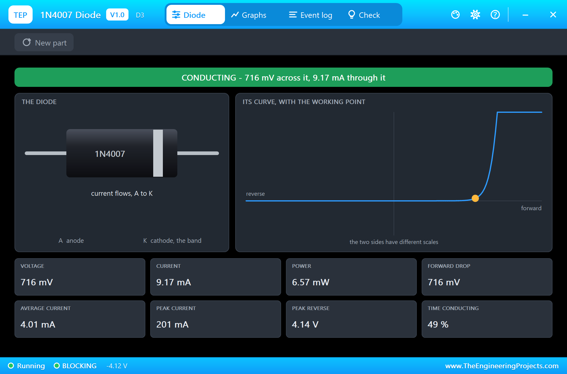
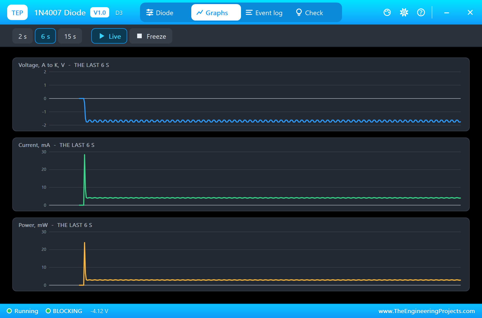
Click D3. With the square wave running, the diode conducts in short bursts while D9 is HIGH and C1 needs topping up, then blocks while D9 is LOW:
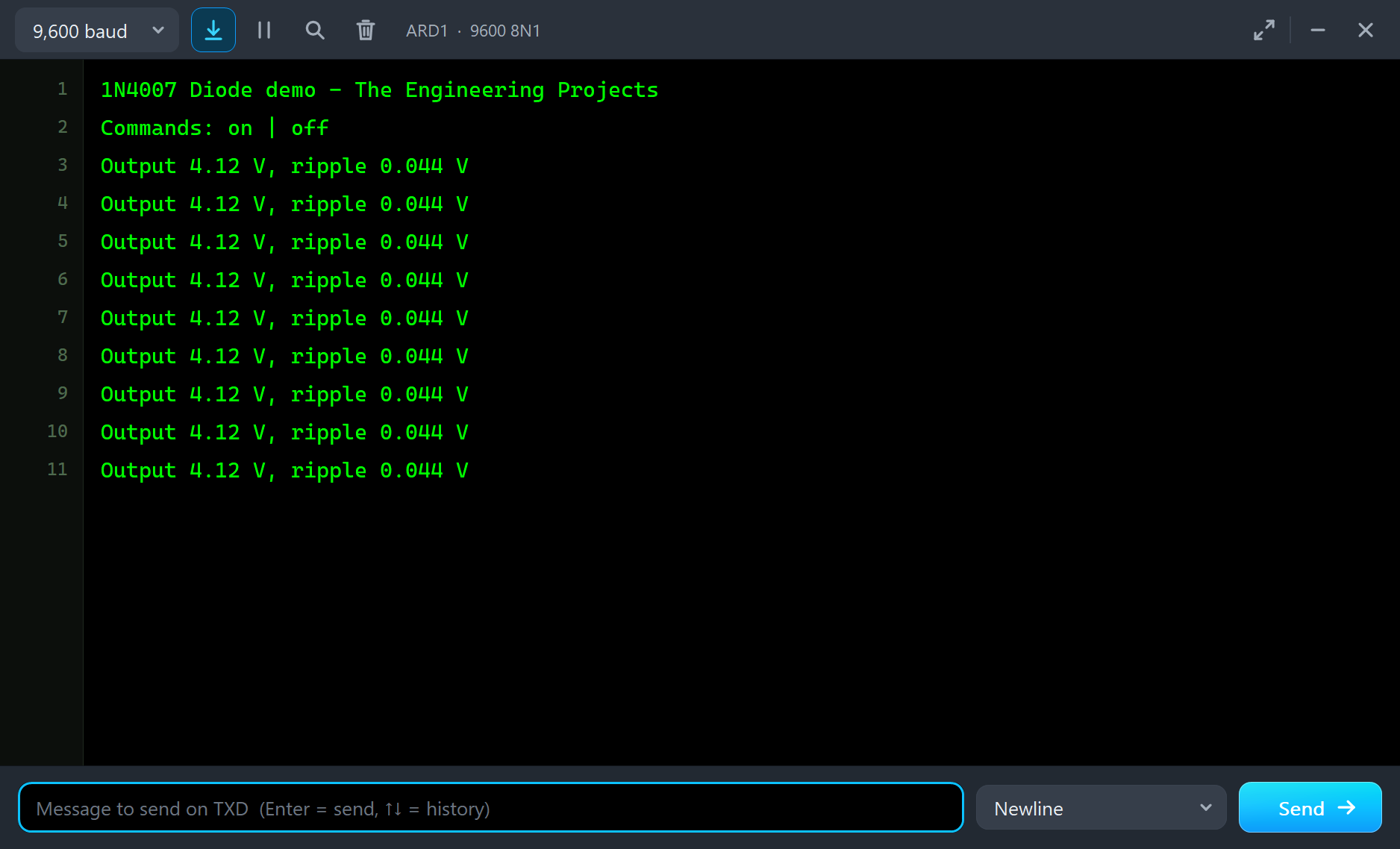
The monitor shows the output and the ripple. The output is less than 5 V for two reasons: the diode's own drop, which the pop-up shows, and the voltage lost inside the Arduino pin while it pushes current. It is steady because C1 holds it up:
Look at the Time Conducting tile on D3's pop-up. A rectifier diode only conducts for part of the cycle, while the pin is above the capacitor's voltage. All the current for the whole cycle has to pass in that short window, so the peak current is much higher than the average. Designers have to allow for this: the diode and the capacitor must both cope with those pulses.
Stop the Wave
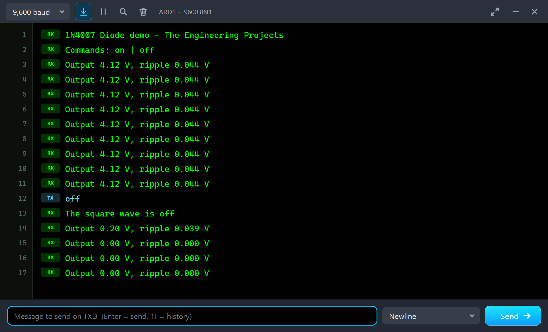
Type off in the monitor. D9 stays LOW, and C1 drains through R3 with a time constant of 1,000 x 0.0001, or 0.1 seconds. The output falls to nothing in less than a second:
The Log and the Check Page
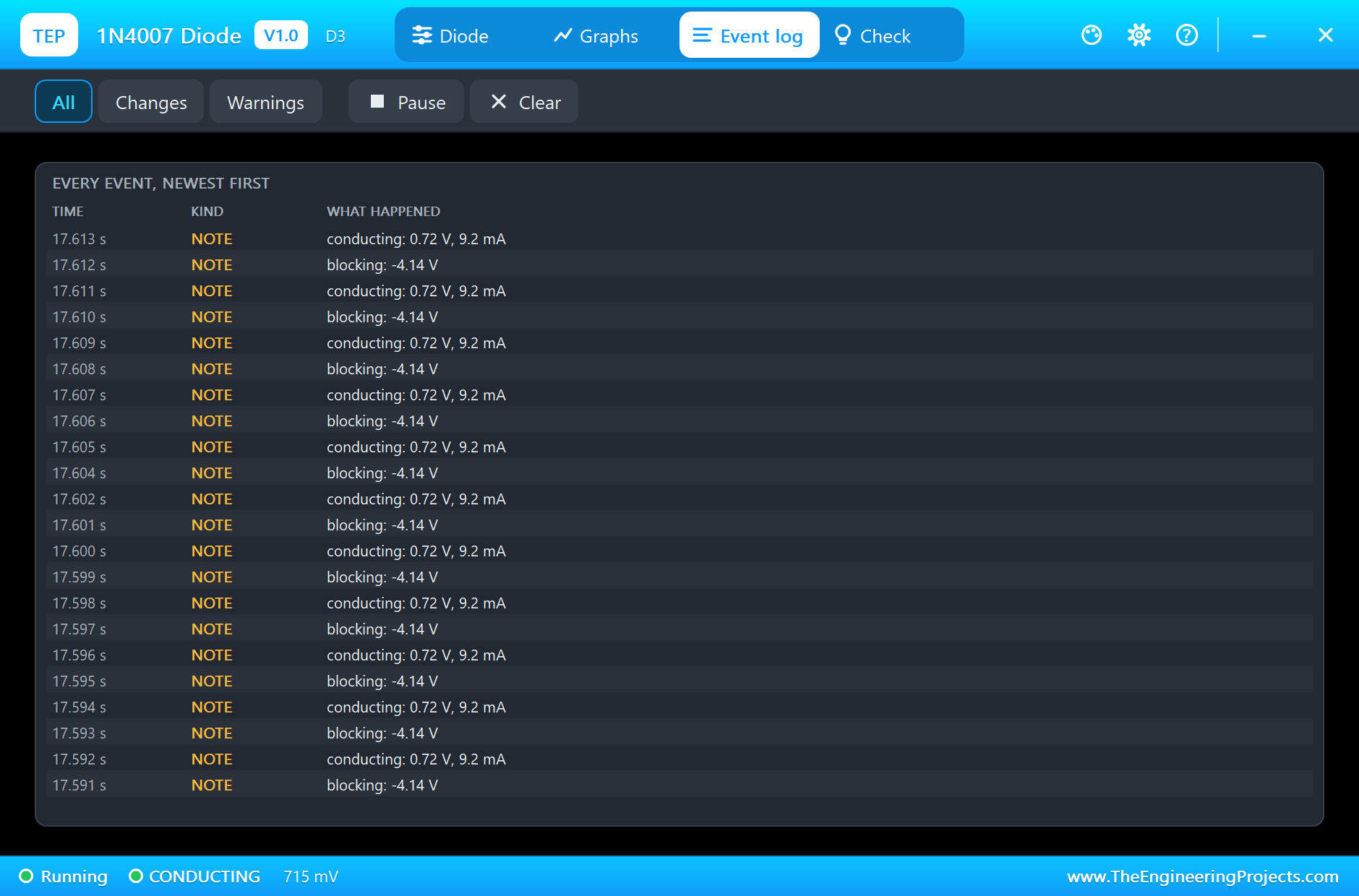
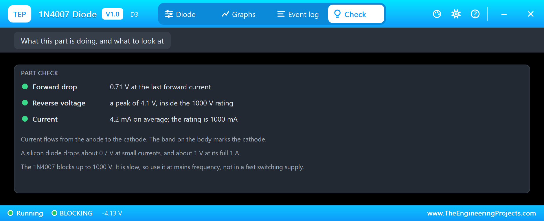
Back on D3, the Event log writes down the changes, and the Check page reads the forward drop and the reverse voltage against the rating:
Try It Yourself
- Remove C1, and watch the ripple jump as the output follows the wave.
- Change R3 to 100 ohm, and see the drop rise a little with the current.
- Change C1 to 1000 uF, and see the ripple shrink.
- Swap D3 for our Schottky diode, and compare the output.
- Put a diode straight across a 5 V rail with no resistor, and see how it fails.
Ideas to Extend the Demo
- Build a flyback circuit for a small relay with a transistor.
- Add a diode in series with a battery input, so that reversing the battery cannot hurt the board.
- Use two diodes to let a board run from either of two supplies.
- Measure the drop against the current, and plot the real curve.
Your Own Sketches
The demo sketch is in the zip file, and you can change it in the Arduino IDE. New to Arduino? Start with our Arduino Tutorial for Beginners. Export the compiled binary, and set the UNO's PROGRAM property to the new file. Our guide on How to get the HEX file from Arduino shows you where the file ends up.
Things to Know Before Using a Real 1N4007
- It is slow: it takes microseconds to stop conducting, so use it at mains frequency. For a switching supply, use a fast or Schottky diode.
- Allow for the drop: 0.7 V is a lot on a 3.3 V rail.
- Keep it cool: at 1 A it wastes about 1 W, and long legs help carry the heat away.
- Failed diodes are usually short: a dead one often reads near zero both ways on a meter.
- The surge is fine: it takes 30 A for a single half cycle, so it survives the rush into a capacitor at switch-on.
- Look after the pin: an Arduino pin will not take that rush. Our demo feeds a capacitor straight from D9, which a real board would not like. On a bench, add about 100 ohm in series.
Troubleshooting
- The LED stays dark: the band is on the wrong side.
- The output is under the pin voltage: that is the diode's drop, and it is normal.
- SHORTED: it was overcooked. Fix the circuit first, then press New part.
- The pop-up does not open: click the diode while the simulation runs.
- The part is not simulated:
TEP1N4007.DLLis missing from MODELS and from the project folder.
Limitations of the Simulation
- The reverse recovery time and the junction capacitance are left out.
- The drop does not change with temperature.
- A real diode may also fail open. Ours always fails short.
- Arduino is a name of Arduino; this library is not made or endorsed by Arduino or Labcenter.
- Tested in Proteus 8.5 in October 2026 (the demo as shipped). Proteus 7 is not supported.
So, that was all about the 1N4007 Diode Library for Proteus. I hope watching that dot move on the curve makes a diode feel less like a rule to remember and more like something you can see. If you have any questions, ask in the comments and I will help you out. Till the next tutorial, take care and have fun!