Hello friends, I hope you all are doing great. Today, I am going to share the new Film Capacitor Library for Proteus. Open a good audio amplifier or a mains power supply, and you will see neat little red or green boxes standing among the other parts. They are film capacitors, and they are the honest workers of the capacitor family: what is printed on the box is very nearly what you get.
Film Capacitor Library for Proteus
Latest version: V1.0 (November 2026, this tutorial)
Other component libraries: C945 Transistor · PC817 Optocoupler · Relay Module · Resistor · 5 mm LED · Designer Colour LED · Push Button · Active Buzzer · Electrolytic Capacitor · Ceramic Capacitor · Tantalum Capacitor · 1N4007 Diode · Zener Diode · Schottky Diode · Supercapacitor · Photodiode · RGB LED · Bridge Rectifier · Flashing LED · Bi-Colour LED · SMD LED · Slide Switch · Toggle Switch · Rocker Switch · Micro Limit Switch · Emergency Stop Switch · SMD Resistor · Power Resistor · Resistor Network · Potentiometer · Trimmer Potentiometer · Slide Potentiometer · NTC Thermistor · DIP Switch · Fuse · Passive Buzzer · Mini Speaker · 7-Segment Display · LED Bar Graph · IR / UV LED · Small Transistors · TIP122 Darlington · N-MOSFET · P-MOSFET · PC817 Optocoupler · Filament Bulb · Power LED · Voltage Regulator · SCR and TRIAC · Inductor · Toroid Inductor · Crystal
Helping Tools
- Serial Monitor Advance: a serial terminal window for the UART of your board
- Serial Monitor Expert: the serial monitor with extra debugging tools
- LCD Library for Proteus V3.0: 16x2, 20x4 and I2C LCDs to show your readings
So we built them in both colours, at true scale, and like our ceramic and tantalum parts they print their own code, which changes when the value changes. For the demo, we put that honesty to the test. We turn an Arduino into a capacitance meter and let it measure the part in the simulation, value after value, all from a resistor, a timer and one simple formula.
NOTICE: Our team has put a lot of effort into these small parts: the bodies, the animation and the pop-ups are all our own design, and you get them free. Your feedback is the fuel that keeps us going, so please tell us what you think in the comments below or in the Film Capacitor board of our forum. And if our free libraries help you, you can buy us a coffee. So, let's get started with the Film Capacitor Library for Proteus:
What is a Film Capacitor?
A film capacitor uses a thin plastic film as the insulator between its plates. In the common type, a long strip of plastic thinner than a hair has a layer of metal sprayed on it. Two of these strips are wound or stacked together, wires or tabs are joined to the metal at each end, and the lot is sealed in a plastic box or dipped in resin. That is why they are so often neat rectangular blocks.
The plastic does not care much about voltage, frequency or temperature, so a film capacitor keeps its value very well, and its losses are low. It has no polarity. It costs more than a ceramic of the same value and it is bigger, but when a circuit's behaviour depends on the true value of the capacitor, this is the part to reach for.
| Feature | The real part | In the library |
|---|---|---|
| Size | 7.2 mm long, 7.5 mm high | 300 x 315 thou, true scale |
| Legs | 5 mm apart | 200 thou apart |
| Value | 1 nF to tens of uF | 1 uF by default, any value |
| Voltage rating | 63 V to 630 V and more | 63 V by default |
| Tolerance | 5 % is common | the code shows J, 5 % |
| Polarity | none | none: pins 1 and 2 are the same |
Polyester or Polypropylene?
Two plastics do most of the work. Polyester, sold as Mylar and marked MKT, is the cheap general-purpose choice, and it gives a good value in a small box. Polypropylene, marked MKP, is bigger for the same value, but it has far lower losses. So it is the choice for audio crossovers, high-frequency circuits and anything carrying a large ripple current.
| Type | Marked | Size | Losses | Good for |
|---|---|---|---|---|
| Polyester | MKT | small | moderate | general filters, timing |
| Polypropylene | MKP | larger | very low | audio, power, high frequency |
Reading the Code
A film capacitor uses the same three-digit code as the ceramics in our Ceramic Capacitor Library for Proteus. The first two digits are the value, the third is the number of zeros, and the answer is in picofarads. So 105 is 10 followed by five zeros, or 1,000,000 pF, which is 1 uF. The letter that follows is the tolerance: J means 5 % and K means 10 %. Larger boxes often skip the code and print the value in full, such as 0.1 for 0.1 uF, along with the voltage rating.
| Code | Value | Tolerance |
|---|---|---|
| 103J | 10 nF | 5 % |
| 104K | 100 nF | 10 % |
| 474J | 470 nF | 5 % |
| 105J | 1 uF | 5 % |
What Makes It So Honest?
Compare it with the other families in this series. A cheap ceramic can lose much of its value when you put a steady voltage on it. An electrolytic in our Electrolytic Capacitor Library is often 20 % out when new, and it drifts as it ages. A tantalum in our Tantalum Capacitor Library is better, but it is still polarised and fussy about surges. A film capacitor has none of those troubles, which is why it is the normal choice for timing circuits and for filters that must stay at the right frequency.
Where You Will Find Them
Look for them in audio equipment, where they pass the signal between stages. They sit in the filters of instruments and in the timing circuits of oscillators. Big versions, marked X2, sit straight across the mains in power supplies and appliances to block noise, and they are built to fail safely. Another job is the snubber: a small film capacitor and a resistor placed across a switch or a motor, where it soaks up the voltage spikes.
Self-Healing
Metallised film has a clever trick. If a tiny flaw in the plastic breaks down, the spark burns away the very thin metal around that spot, which isolates it. The capacitor loses a tiny amount of value and carries on working. This is called self-healing, and it is why film parts are trusted across the mains. It also means that a badly overstressed film capacitor slowly fades instead of failing all at once.
Features of the Film Capacitor Library for Proteus
- The real look, at true scale: a neat box in red or green, with its code, its voltage and our small TEP signature.
- It prints its own code: 17 values from 10 nF to 4.7 uF, and the digits on the box follow the value.
- A live charge bar: a small bar on the box follows the voltage at Run.
- A true capacitor: a capacitance behind a very small ESR in the analog simulator, with no polarity.
- A pop-up for every part: click it at Run for the code explained, the charge, eight live values, graphs, an event log and a check page.
- Live changes: step the value through the E6 series while it runs, and watch the code change on the box.
- A complete package: about 1.8 MB with the library, our Arduino UNO V4.0, the demo's resistors and LED and the demo, without the source code of the models.
The Film Capacitor in Proteus
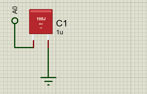
The two devices are CAPFILMREDTEP and CAPFILMGREENTEP in TEPFILM.LIB, under Capacitors, Polyester Film, with the prefix C and the model TEPFILM.DLL. Search CAPFILM in Pick Devices. It has two pins, 200 thou apart, and either way round is fine.
The Properties
| Property | What it does |
|---|---|
| Capacitance | the value: 1u, 470n or 100n; a bare number is in uF |
| Voltage rating, V | the working voltage, 63 by default |
| Series resistance (ESR), ohm | 0.02 ohm by default |
| Printed code while stopped | the digits shown on the stopped sheet |
The box shows its code while the simulation is stopped, because the code is one of 17 ready-drawn looks of the part. At Run, the model reads the Capacitance box and sets the code to match.
Download Film Capacitor Library for Proteus
Click the button below to download Film-Capacitor-Library-for-Proteus-v1.0.zip (about 1.8 MB, without the source code of the models):
Film Capacitor Library for Proteus V1.0- README.txt: installation, the demo, the properties, troubleshooting and the limits.
- Proteus Library Files:
TEPFILM.LIB,TEPRESISTOR.LIB,TEPLED5MM.LIBand ourArduinoV4TEP.LIB. - Proteus Model Files:
TEPFILM.DLL,TEPRESISTOR.DLL,TEPLED5MM.DLLandTEPARDUINO.DLL. - Arduino Code: the demo sketch.
- Proteus Simulation: the demo project, its HEX file and copies of the DLLs.
No Proteus yet? Read How to Download and Install Proteus 7 and 8. New to libraries? Follow How to Install a New Library in Proteus.
How to Install Film Capacitor Library for Proteus
- Close Proteus and extract the whole zip file, for example to your Desktop.
- Copy the files from Proteus Library Files into the LIBRARY folder of Proteus.
- Copy the files from Proteus Model Files into the MODELS folder.
- Delete
TEPFILM.IDXfrom the LIBRARY folder if it is there. - Start Proteus, press P and search for CAPFILM.
Demo: An Arduino Capacitance Meter
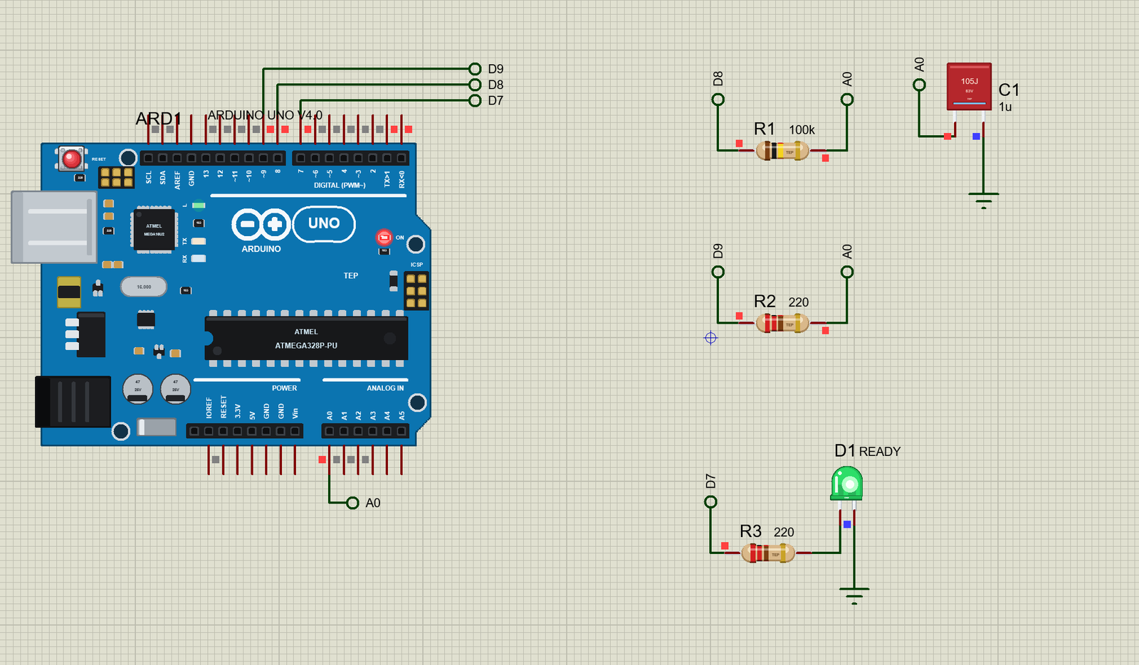
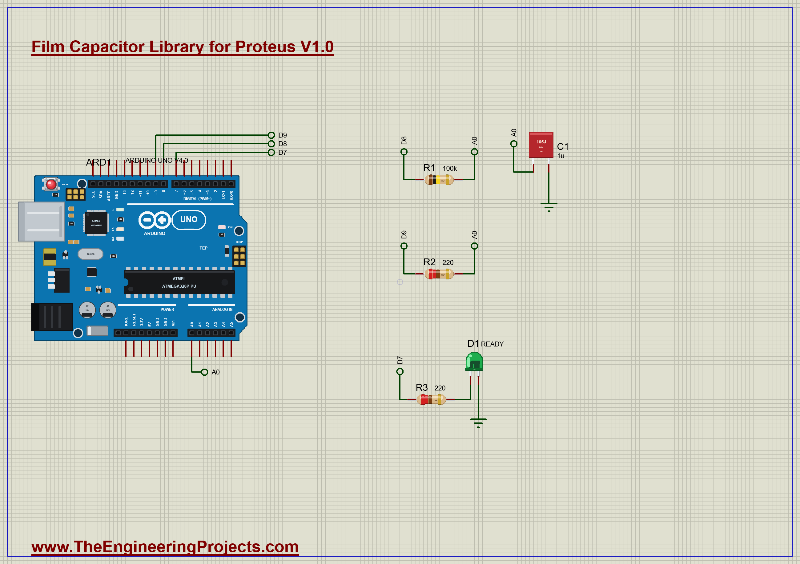
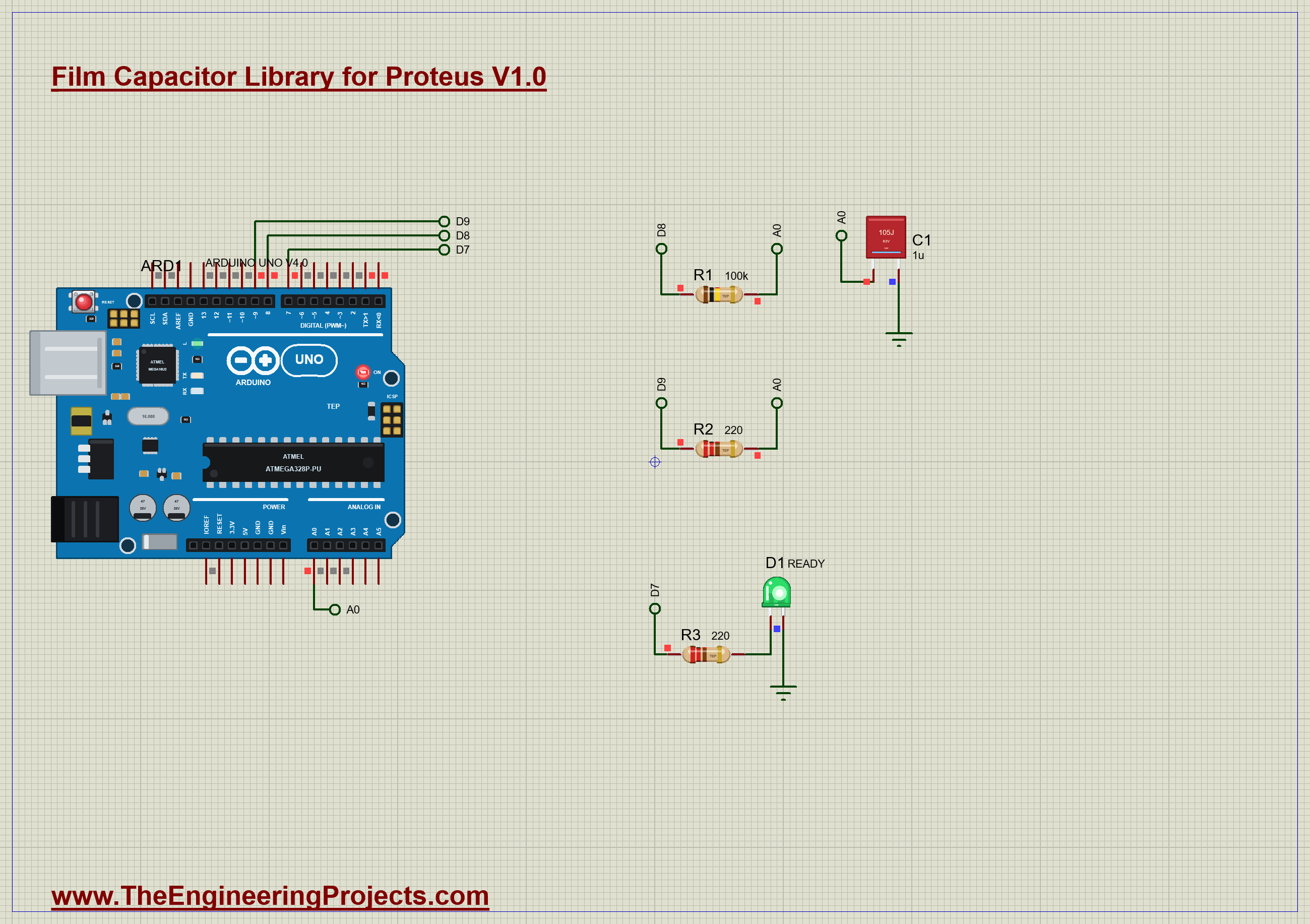
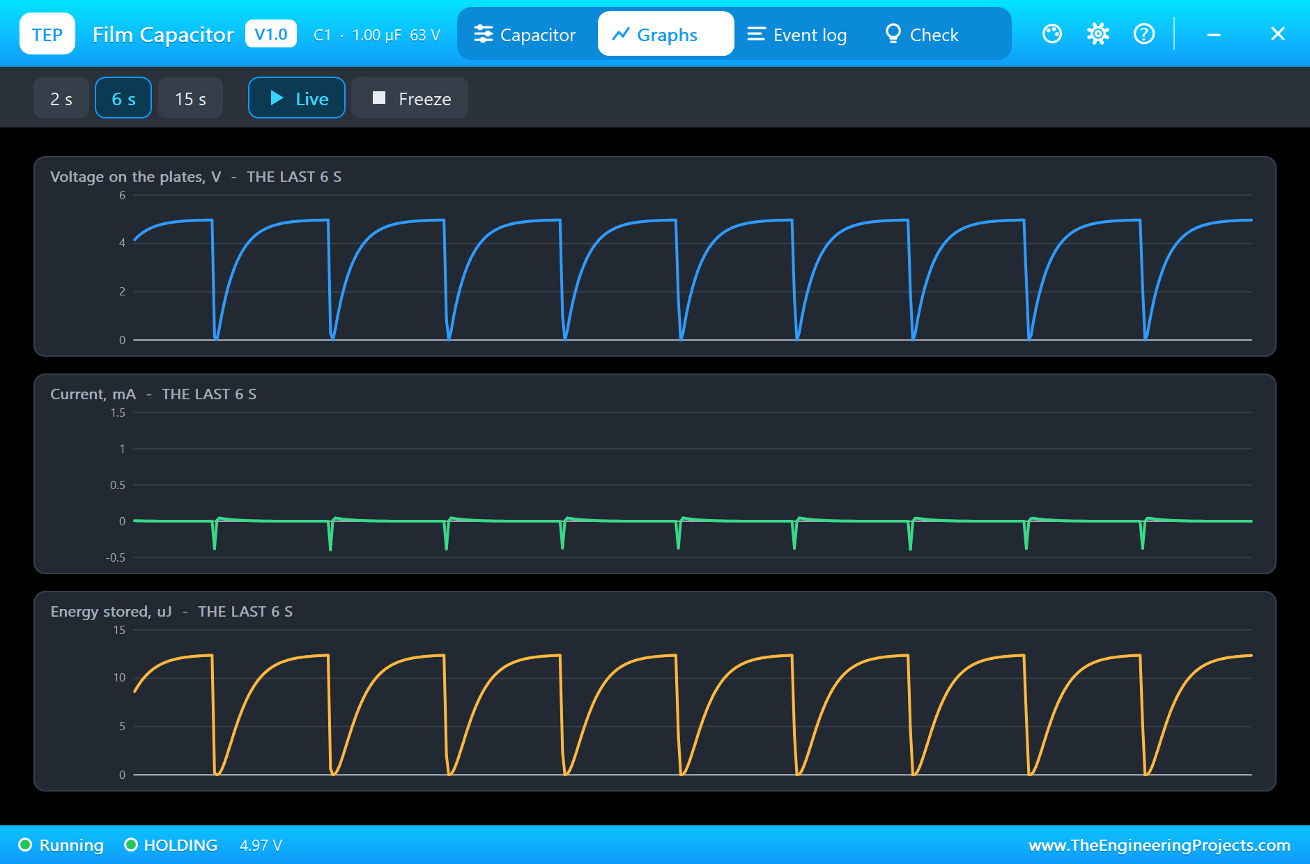
A capacitor charging through a resistor reaches 63.2 % of the supply in exactly one time constant, R x C. So if you know R, and you can time how long the voltage takes to get there, you can work out C. That is all a basic capacitance meter does. Open Film-Capacitor-Meter-ArduinoUnoV4.pdsprj. It runs on our Arduino UNO Library for Proteus V4.0, with its built-in monitor, the same window as our TEP Serial Monitor Advance for Proteus. The resistors are from our Resistor Library for Proteus.
| Part | Connection | Job |
|---|---|---|
| R1, 100k | D8 to A0 | the known resistor |
| C1, 1 uF | A0 to GND | the capacitor under test |
| R2, 220 ohm | D9 to A0 | empties C1 quickly |
| D1, green | D7, through 220 ohm | lights when a reading is ready |
How the Meter Works
The sketch runs one measurement after another. First it empties C1, using D9 as an output held LOW, so C1 drains through R2 in moments. Then D9 becomes an input, which takes it out of the circuit. D8 goes HIGH, and the timer starts. The sketch reads A0 as fast as it can until the reading reaches 647, which is 63.2 % of the full 1023. The time at that moment is R x C:
  unsigned long start = micros();
  digitalWrite(CHARGE_PIN, HIGH);
Then it is just a division. With the time in microseconds and R in ohms, the result comes out neatly in microfarads:
float uF = took / R_KNOWN;With 100k and 1 uF, the time should be 100 ms. It is a slow enough speed for a sketch to time well, as analogRead() takes only about a tenth of a millisecond.
Run the Demo
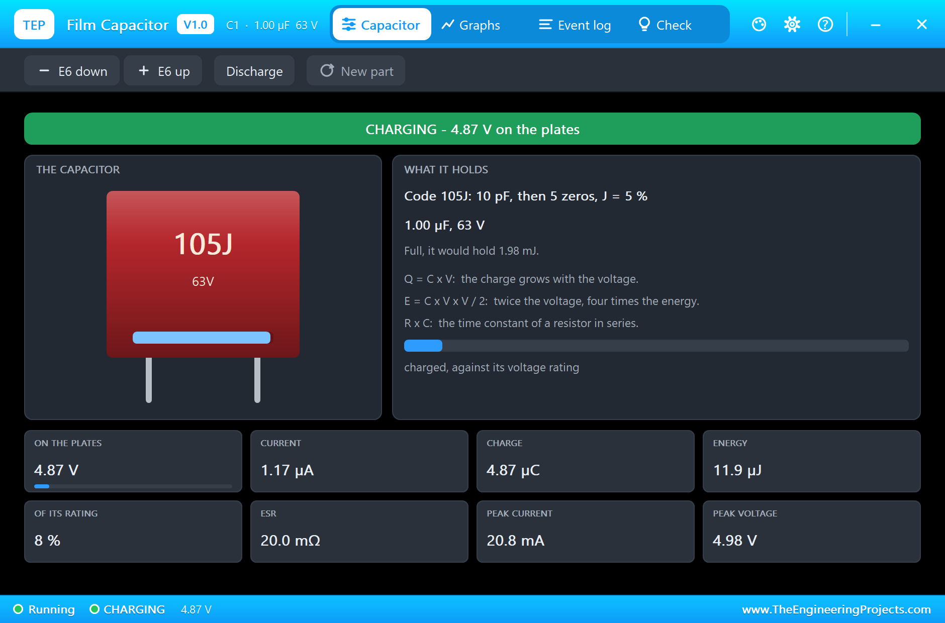
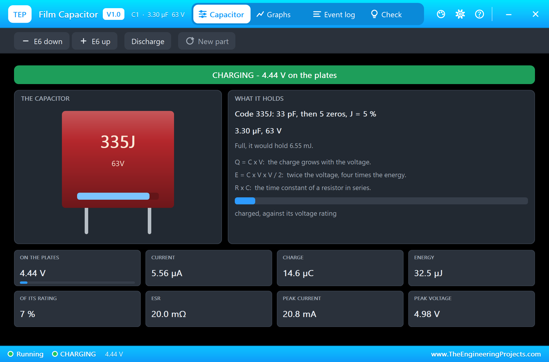
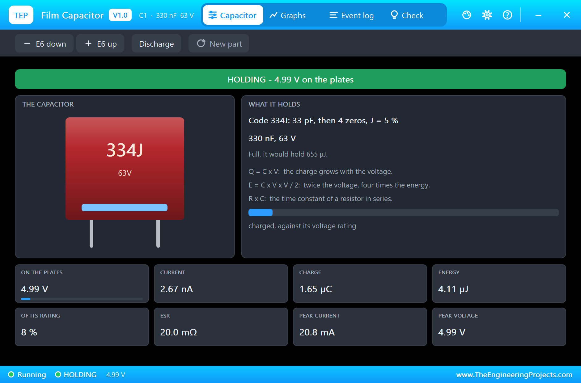
Press Run and the monitor opens. Click the box to open its pop-up. The right-hand card explains the code, and you can see the charge bar moving as the sketch charges and empties the part:
Here is the complete meter, truly running, with the green LED showing that a reading is ready:
Test the Meter
Now press E6 up and E6 down on the pop-up. Each press changes the value and the code on the box, and a moment later the meter finds the new value. Here is what it read in the final run:
| On the box | Code | Time to 63 % | The meter says |
|---|---|---|---|
| 3.3 uF | 335J | 330.3 ms | 3.30 uF |
| 2.2 uF | 225J | 220.4 ms | 2.20 uF |
| 1.5 uF | 155J | 150.4 ms | 1.50 uF |
| 1 uF | 105J | 100.4 ms | 1.00 uF |
| 680 nF | 684J | 68.4 ms | 684 nF |
| 470 nF | 474J | 47.4 ms | 474 nF |
| 330 nF | 334J | 33.3 ms | 333 nF |
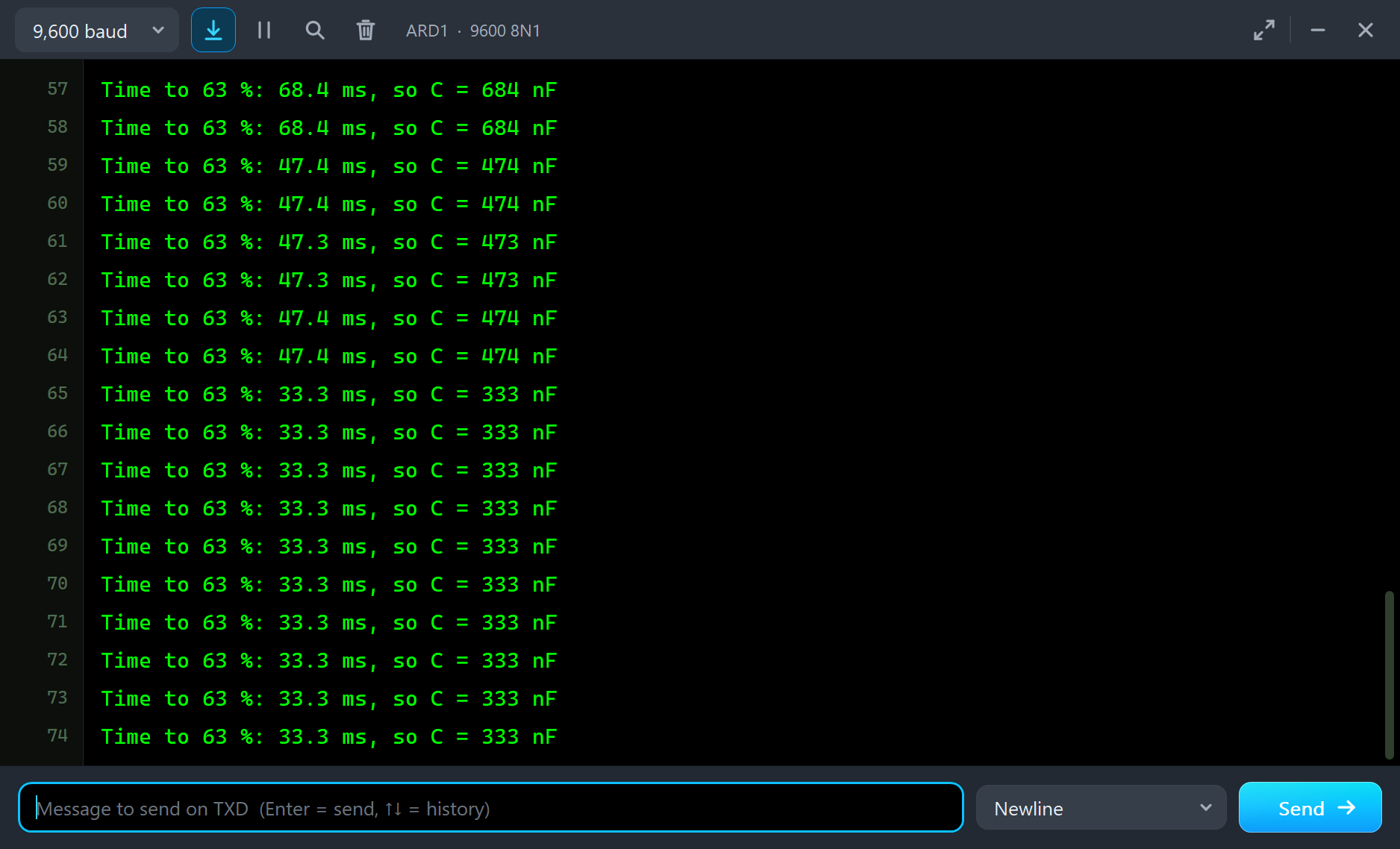
Look at the time column. It runs a steady 0.3 to 0.4 ms long at every value, so the error is a fixed extra and not a percentage. The sketch can only notice the crossing after it has finished reading A0, and it has its own work to do at the start of the charge. A fixed error hardly shows at 3.3 uF, but it grows in importance as the time gets shorter, which is why the small values read slightly high. On a real bench, the tolerance of R1 would matter far more than this. A 5 % resistor gives a meter that is only good to 5 %.
The Range of the Meter
With 100k, the sketch gives up after 3 seconds, so the top of the range is about 30 uF. The bottom is set by that fixed 0.4 ms of error. At 10 nF the true time is only 1 ms, so the extra 0.4 ms would add 40 % to the reading. A real meter gets round this by switching resistors. With 1k, it can time large capacitors quickly, and with 1M or more, it can stretch out small ones until the timing error no longer matters. This is exactly the job that the range switch does on a bench meter.
Bench LCR meters work differently again. They do not wait for one charge at all. Instead they apply a small AC signal and measure both the current and its phase, which also reveals the ESR and the losses of the part. Our little meter only finds the capacitance, but it uses the same idea that sits behind every instrument of this kind: turn the thing you want to know into something you can count.
The Curve
The Graphs tab shows why this works. Each measurement draws the classic charging curve, again and again, and each one stops when the sketch has its reading:
The Log and the Check Page
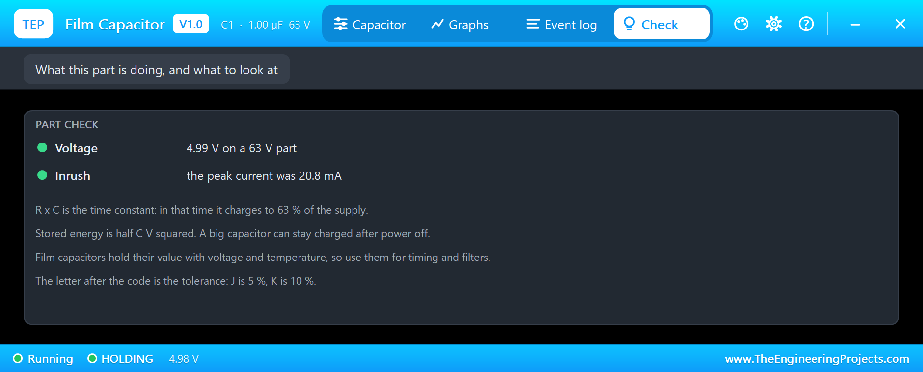
The Event log lists every charge and discharge, and the Check page looks at the voltage against the rating:
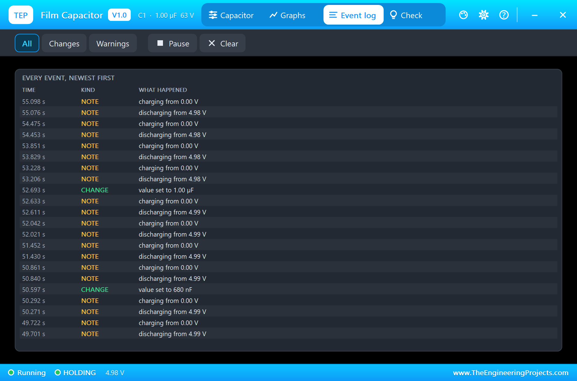
A value set by the chips lasts for this run only. To keep it, type it in the Capacitance box.
You may also wonder why the sketch bothers with a separate pin to empty the capacitor. It could simply take D8 LOW, and C1 would drain through R1. But that takes five time constants, half a second at 1 uF, and it would hold up every measurement. Through 220 ohm, the same job takes about 5 ms. Making D9 an input afterwards is the neat part: an input pin draws almost nothing, so R2 vanishes from the circuit, and it cannot disturb the timing.
Try It Yourself
- Change
R_KNOWNin the sketch to 99000, leave R1 alone, and see the error it causes. - Change R1 to 10k and
R_KNOWNto match, then step the capacitor to 100 nF and see how the timing suffers. - Add a second capacitor in parallel, and check that the two values add up.
- Swap C1 for our electrolytic capacitor, and measure 10 uF.
- Print the error against the value set on the box.
Ideas to Extend the Demo
- Show the reading on an LCD and make a real pocket meter.
- Pick the resistor automatically, 1k or 100k, so that the meter covers more ranges.
- Sort a box of unmarked capacitors by value.
- Measure the same part at the start and end of a day, and see how it drifts.
Your Own Sketches
The demo sketch is in the zip file, and you can change it in the Arduino IDE. New to Arduino? Start with our Arduino Tutorial for Beginners. Export the compiled binary, and set the UNO's PROGRAM property to the new file. Our guide on How to get the HEX file from Arduino shows you where the file ends up.
Things to Know Before Using a Real Film Capacitor
- Mind the size: a film part is much bigger than a ceramic of the same value, so check the space and the leg spacing.
- Use X2 parts on the mains: only a safety-rated part may sit across the mains. An ordinary box is not safe there.
- Watch the AC rating: the printed DC voltage is not the AC voltage it can take.
- Discharge it first: a good film capacitor can hold its charge for a very long time.
- Keep the soldering short: too much heat can damage the plastic film.
Troubleshooting
- The code does not match the value: press Run once. The model sets the code to the nearest E6 value.
- The meter prints no capacitor: C1 is open, or it is more than about 30 uF.
- BURST: it saw too much voltage. Fix the circuit first, then press New part.
- The pop-up does not open: click the box while the simulation runs.
- The part is not simulated:
TEPFILM.DLLis missing from MODELS and from the project folder.
Limitations of the Simulation
- The self-healing of metallised film is left out, and so is the inductance of the part.
- The tolerance is not modelled: the part is exactly its value, however the code reads.
- The chips on the pop-up change the current run only.
- Arduino is a name of Arduino; this library is not made or endorsed by Arduino or Labcenter.
- Tested in Proteus 8.5 in October 2026 (the demo as shipped). Proteus 7 is not supported.
So, that was all about the Film Capacitor Library for Proteus. I hope you enjoy building a real instrument out of a resistor and a little sketch, and that the neat red boxes earn a place in your next design. If you have any questions, ask in the comments and I will help you out. Till the next tutorial, take care and have fun!