Hello friends, I hope you all are doing great. Today, I am going to share the new Vertical-Axis Wind Turbine Library for Proteus V1.0, the fourth part of our renewable energy series. You have probably seen one on a rooftop, a lamp post or a school roof: a short, twisted "barrel" of two curved buckets spinning on a vertical shaft. That is a helical Savonius wind turbine, the simplest wind turbine there is - it starts by itself, it takes the wind from any side, and it is quiet and safe.
Vertical-Axis Wind Turbine Library for Proteus
Latest version: V1.0 (November 2026, this tutorial)
Other power libraries: LiPo Battery · Single Cell Battery · CR2032 Coin Cell · Solar Panel · MC34063 Buck · MC34064 Boost · 12V Solar Panel · 6V Mini Solar Panel · 3-Phase PM Generator
Helping Tools
- Serial Monitor Advance: a serial terminal window for the UART of your board
- Serial Monitor Expert: the serial monitor with extra debugging tools
- LCD Library for Proteus V3.0: 16x2, 20x4 and I2C LCDs to show your readings
This library puts that turbine into Proteus - the rotor, its curves and its moods. Its torque and its power follow the wind and the load: a load that fits the wind holds it at its best point, a lighter one lets it race, too heavy a one stalls it. Its shaft is a real pin: it drives our new 3-Phase PM Generator Library for Proteus through a wire, and the turbine, the generator, the rectifier and the load are simulated together. The demo measures the whole chain from an Arduino UNO V4.0.
NOTICE: a wind turbine in a circuit simulator is usually just a voltage source that follows a "wind" number. Our team put a lot of effort into building one that behaves like the real thing: a rotor with its own torque curve and inertia, a shaft that a generator really loads, a stall, gusts - and buckets you can watch turn on the sheet. Your feedback is the fuel that keeps us going, so please tell us what you think in the comments below or in the Motor Driver board of our forum. And if our free libraries help you, you can buy us a coffee. So, let's get started with the Vertical-Axis Wind Turbine Library for Proteus V1.0:
What is a Vertical-Axis Wind Turbine?
A vertical-axis wind turbine (VAWT) turns around a vertical shaft, so the wind can come from any side and there is nothing to steer. The Savonius type has two (or three) curved buckets: the wind pushes harder on the hollow side of one bucket than on the round back of the other, and the rotor turns. A helical Savonius twists the buckets along the height, so the rotor always has a bucket facing the wind - it turns smoothly and starts from any angle.
| The helical Savonius turbine (the model) | |
|---|---|
| Rotor | two buckets twisted 180 degrees, 0.26 m across, 0.70 m tall (0.18 m2) |
| Best power coefficient | Cp 0.18 at a tip speed ratio of 0.8 |
| On its shaft | about 19 W at 10 m/s near 560 RPM; 9.5 W at 8 m/s; 1 W at 4 m/s |
| Starts | by itself, at about 1.7 m/s with the generator on it |
| Drive | a 1:1 right-angle gearbox to the SHAFT pin |
| Properties | WIND (m/s), GUSTS (NO or YES) |
Drag and Lift: Savonius and Darrieus
A Savonius is a drag rotor: the wind pushes its buckets, so the buckets can never move faster than the wind. Its torque is largest when it stands still - which is why it starts by itself - and falls as it speeds up. The other vertical-axis type, the Darrieus, has thin wings that work by lift: it runs faster and catches more of the wind, but it needs a push to start. Small rooftop turbines often use a Savonius for exactly that reason: it starts in a light wind and never needs help.
The Tip Speed Ratio and the Best Point
The tip speed ratio is the speed of the buckets' edges divided by the wind speed. In our model the rotor's torque falls in a straight line with it, from its largest at standstill to nothing at about 1.6, where the rotor runs free with no load. Power is torque times speed, so it is zero at both ends and peaks in the middle: a power coefficient of 0.18 at a tip speed ratio of 0.8. That peak is the best point, and it moves with the wind - so a load that is perfect for 10 m/s is too heavy for 8 m/s.
Why the Generator Is a Separate Library
A turbine and its generator are two different machines joined by a shaft. In this series the generator is its own library, and the turbine drives it through its SHAFT pin: the shaft is an electrical net where 1 V means 1 RPM and 1 A means 1 N.m of torque. The turbine pushes its torque into the net, the generator takes out what its load needs, and Proteus solves the two together. The same generator can be driven by other prime movers later - and the same turbine could drive another generator.
What's New in Vertical-Axis Wind Turbine Library for Proteus V1.0
- A part of its own - just the turbine: the two aluminium buckets between their end plates, the column, and the right-angle gearbox with its output shaft.
- Buckets that turn on the sheet: at Run the library draws them at the rotor's angle and repaints the part - with no box behind the rotor, the sheet shows between its buckets.
- A real rotor: its torque curve, its inertia, its bearings and its air drag; it starts by itself, finds its speed, stalls under too much load and races with none.
- The wind: five wind speeds, gusts and a turning wind on the pop-up.
- A SHAFT pin that drives our 3-Phase PM Generator, so the whole chain from the wind to the battery side is simulated.
- A pop-up window with the rotor's power and torque curves, the best point, the live values and a wind scene with a compass.
The Vertical-Axis Wind Turbine in Proteus
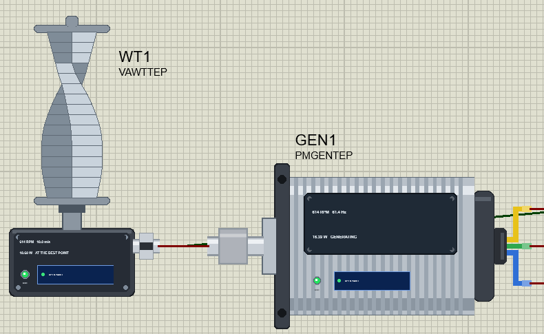
Search wind or VAWT in Pick Devices; the device VAWTTEP is in TEPVAWT.LIB (category Electromechanical, Renewable Energy) and its model is TEPVAWT.DLL. The symbol is just the turbine: the two twisted aluminium buckets between their end plates, the top bearing cap, the column with the lower bearing, and the cast right-angle gearbox at the foot with its output shaft and coupling on the right - the SHAFT pin.
At Run the buckets turn. The library draws them as shapes at the rotor's angle and repaints the part up to four times a second, so nothing is painted behind them - the sheet's grid shows between the buckets. When the rotor turns fast, it is shown turning steadily forwards. On the gearbox's face the value line shows the RPM, the wind, the watts and the state; the OUT LED lights while the rotor drives its shaft; OPEN PANEL opens the pop-up. The value line, the LED and the button are TEP additions; a real turbine has none of them.
The Pin and the Properties
| Pin | What the model does with it |
|---|---|
| SHAFT | the shaft: the rotor pushes its torque into this net (1 V = 1 RPM, 1 A = 1 N.m) |
| Property | Default | What it does |
|---|---|---|
| WIND | 10 | the wind at the start, in m/s (0 to 20) |
| GUSTS | NO | YES starts with gusts: the wind swings 30 % around its mean |
Download Vertical-Axis Wind Turbine Library for Proteus
Click the button below to download Vertical-Axis-Wind-Turbine-Library-for-Proteus-v1.0.zip (about 1.2 MB, without the source code of the models):
Vertical-Axis Wind Turbine Library for Proteus V1.0- README.txt: installation, the demo, the wiring, the properties, real hardware, troubleshooting and the limits.
- Proteus Library Files:
TEPVAWT.LIBandArduinoV4TEP.LIBfrom our Arduino Library for Proteus V4.0. - Proteus Model Files:
TEPVAWT.DLLandTEPARDUINO.DLL. - Proteus Simulation:
Vertical-Axis-Wind-Turbine-Generator-INA219-ArduinoUnoV4.pdsprj,VAWT_Demo.hexand copies of the DLLs. - Arduino Code:
VAWT_Demo.ino(only the Wire library of the Arduino core).
Good to know: the demo uses two of our other libraries, separate downloads that are not in this zip: the 3-Phase PM Generator Library for Proteus (TEPPMGEN.LIB and TEPPMGEN.DLL: the generator and the rectifier board) and the INA219 Current Sensor Library for Proteus (TEPINA219.LIB and TEPINA219.DLL). Install both the same way.
No Proteus yet? Read How to Download and Install Proteus 7 and 8. New to libraries? Follow How to Install a New Library in Proteus.
How to Install Vertical-Axis Wind Turbine Library for Proteus
- Close Proteus and extract the whole zip file, for example to your Desktop.
- Copy
TEPVAWT.LIBandArduinoV4TEP.LIBfrom Proteus Library Files into the LIBRARY folder of Proteus (usuallyC:\Program Files (x86)\Labcenter Electronics\Proteus 8 Professional\LIBRARY). - Copy
TEPVAWT.DLLandTEPARDUINO.DLLfrom Proteus Model Files into the MODELS folder. The two Arduino files are the ones of our Arduino Library V4.0; if you have it, they are the same. - Install the 3-Phase PM Generator and the INA219 Current Sensor libraries the same way if you do not have them yet.
- Delete
TEPVAWT.IDXfrom the LIBRARY folder if it is there. - Start Proteus, press P and search for wind.
Tip: keep the Proteus Simulation folder together, because the project needs its .hex file and the DLLs beside it. The library is tested in Proteus 8.5; Proteus 7 is not supported.
The Demo Circuit
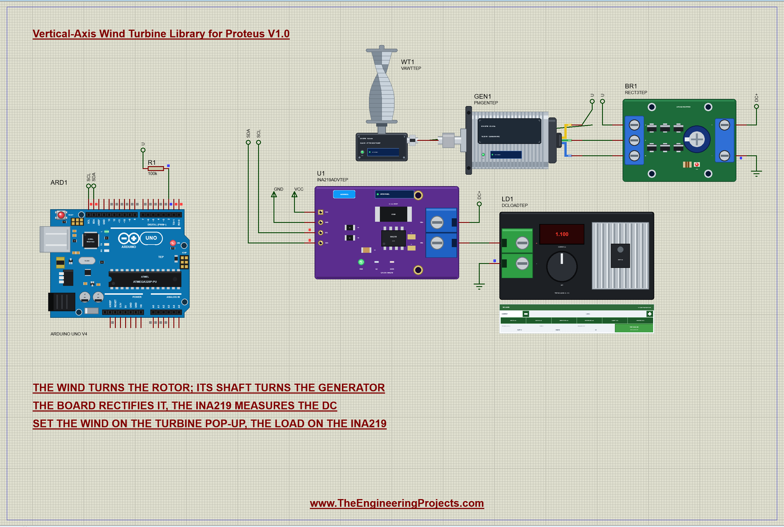
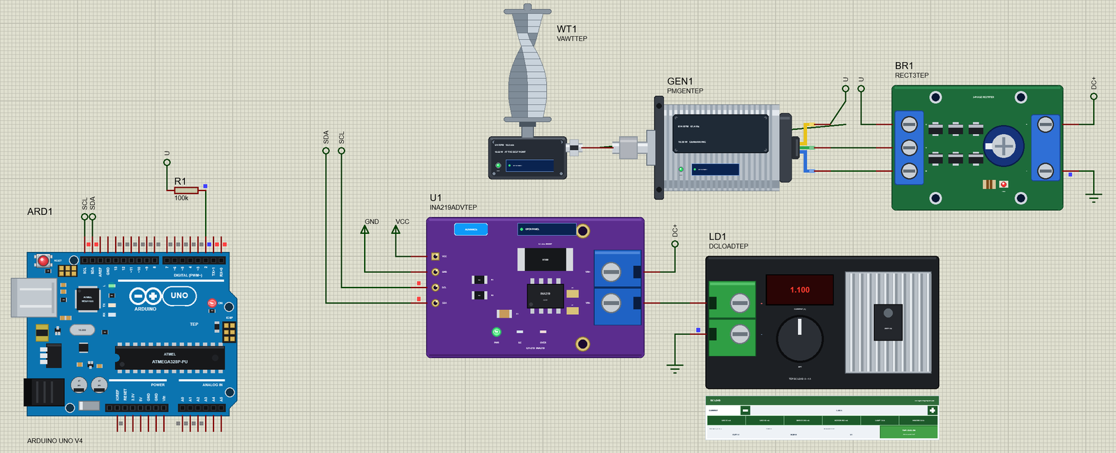
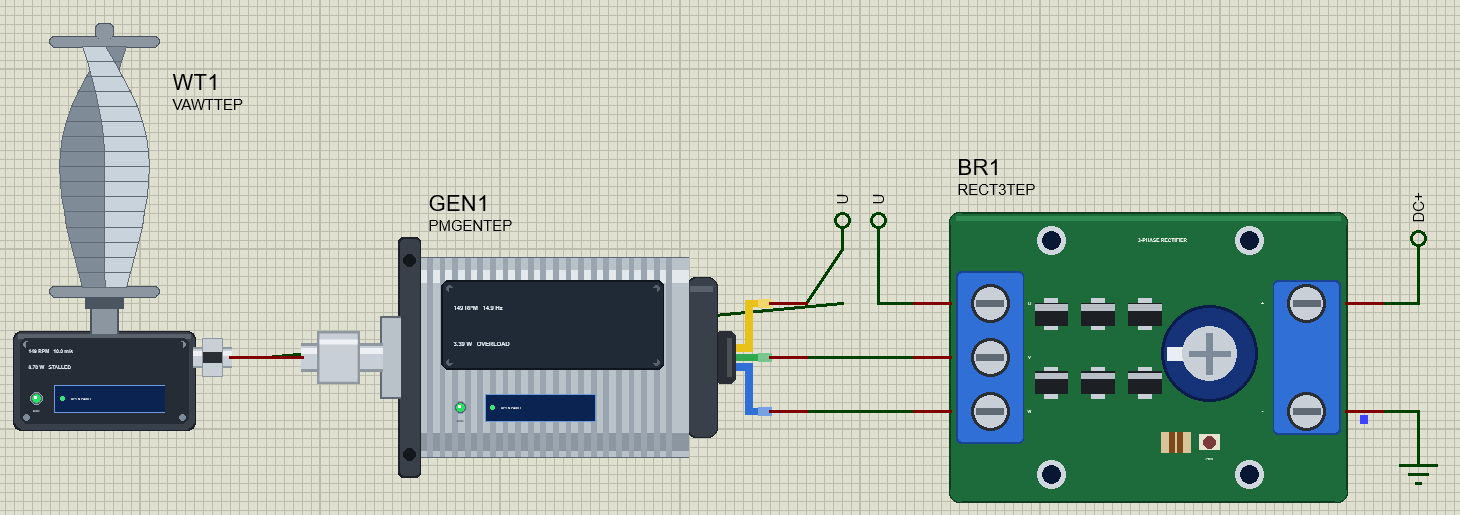
Open Vertical-Axis-Wind-Turbine-Generator-INA219-ArduinoUnoV4.pdsprj. WT1 is the turbine in a 10 m/s wind; one wire joins its SHAFT pin to the SHAFT pin of GEN1, our 3-phase PM generator (PMGENTEP) with its DRIVE property set to SHAFT, so the turbine is the only thing that turns it. From there the circuit is the generator library's demo: the rectifier board BR1 (RECT3TEP), our INA219 U1, the electronic load LD1 set to 1.1 A - the best load for this wind - and R1, which brings phase U to the UNO's D2. ARD1 is an Arduino UNO V4.0 from our Arduino UNO Library for Proteus V4.0, running VAWT_Demo.hex.
| Part | Pin | Goes to |
|---|---|---|
| WT1 | SHAFT | GEN1's SHAFT (one wire: the shaft) |
| GEN1 | V, W | BR1's V and W (straight wires) |
| GEN1, BR1, R1 | U | the U label: one net |
| BR1 | + | the DC+ label, which joins the INA219's VIN+ |
| INA219 | VIN- | the DC load's + (a straight wire) |
| INA219 | SDA, SCL | the UNO's A4 and A5 (SDA and SCL labels) |
| R1 (100k) | the other end | the UNO's D2 |
Why the Load Matters
A wind turbine does not decide its own speed: the wind pushes, the load holds back, and the rotor settles where the two torques meet. The DC electronic load sets exactly how much current - and so how much torque - the generator takes, which makes it easy to show a load that fits the wind, one that is too light, and one that is too heavy. The INA219 measures what reaches the DC side, and the Arduino reads the rotor's speed from the generator's AC.
The Arduino Code
The sketch is the generator library's sketch with the turbine's banner and one more note. It needs only the Wire library of the Arduino core. New to Arduino? Start with Arduino Tutorial for Beginners and Introduction to Arduino UNO. It knows the INA219, the speed input, the generator's pole pairs and roughly what an Arduino UNO needs:
const byte INA = 0x40;
const float SHUNT_OHM = 0.1;
const byte TACH = 2;                          // INT0: phase U through 100k
const byte POLE_PAIRS = 6;                    // the generator's: 12 poles
const float ARDUINO_W = 0.25;                 // an Arduino UNO: about 50 mA at 5 V
The Rotor's Speed from the AC
Phase U swings once per electrical cycle, so every rising edge on D2 is one cycle. The interrupt keeps the times of the last nine edges:
void onEdge() { edgeUs[edgeAt] = micros(); edgeAt = (edgeAt + 1) % 9; if (edgeCount < 9) edgeCount++; }The frequency comes from the last eight whole cycles, and the first four are compared with the last four, so a speed that is still changing is marked:
  const unsigned long first = middle - oldest, last = newest - middle;
  steady = labs((long)first - (long)last) < (long)(last / 50) + 200;
  return 8e6 / (newest - oldest);
The generator has 6 pole pairs, so the RPM is the frequency times 60 divided by 6 - and because the turbine's gearbox is 1:1, that is the rotor's own RPM:
const float rpm = hz * 60 / POLE_PAIRS;The DC Side
The rectified supply ripples at six times the AC frequency, so the sketch averages 16 INA219 readings about 1.2 ms apart:
  for (byte k = 0; k < 16; ++k) {
    const long b = (uint16_t)readReg(0x02) >> 3;  // 4 mV a step
    if (k < 8) bus1 += b; else bus2 += b;
    shunt += readReg(0x01);                       // 10 uV a step
    delayMicroseconds(1100);
  }
amps = shuntV / SHUNT_OHM;
volts = (bus1 + bus2) / 16.0 * 0.004 + shuntV; // the board's own volts: the bus plus the shunt's dropThe Report
Every second the sketch prints the speed, the frequency and the DC volts, amps and watts, with a note - and the question every small turbine project asks, whether the wind would run an Arduino:
  if (!steady) Serial.print(F("  - changing"));
  else if (rpm < 5) Serial.print(F("  - stopped"));
  else if (amps < 0.002) Serial.print(F("  - no load"));
  else if (watts >= ARDUINO_W) Serial.print(F("  - enough for an Arduino"));
rate 500 changes the interval (200 to 5000 ms), best prints the best point so far and reset forgets it. The sketch also writes the INA219's calibration register once:
writeReg(0x05, 4096); // the calibration: 0.1 mA a step in the Current registerThe HEX file is in the package. To change the sketch, open it in the Arduino IDE and export the compiled binary, as in How to get the HEX file from Arduino. It needs 10,250 bytes of flash (31 % of the UNO) and 538 bytes of RAM.
Running the Demo
Press Run. The UNO's serial monitor and the pop-ups of the turbine, the generator and the INA219 open over the schematic; move them aside. In the 10 m/s wind the rotor starts by itself and spins up to its best point in about 8 seconds, and the sketch introduces itself:
Vertical-Axis Wind Turbine demo - The Engineering Projects
The rotor turns the generator; phase U on D2 gives the speed; the INA219 (0x40 on A4 / A5) measures the DC.
Commands: best | reset | rate 1000 | help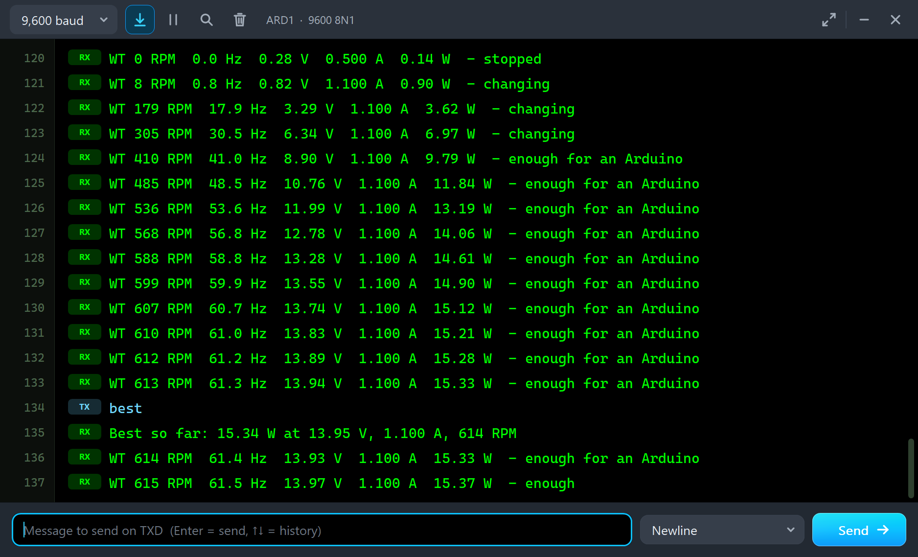
At the Best Point
With the load at 1.1 A, the rotor settles at its best point for this wind: "AT THE BEST POINT - 610 RPM, 0.291 N.m: 18.59 W on the shaft at 10.0 m/s (tip speed ratio 0.83, Cp 0.18)".
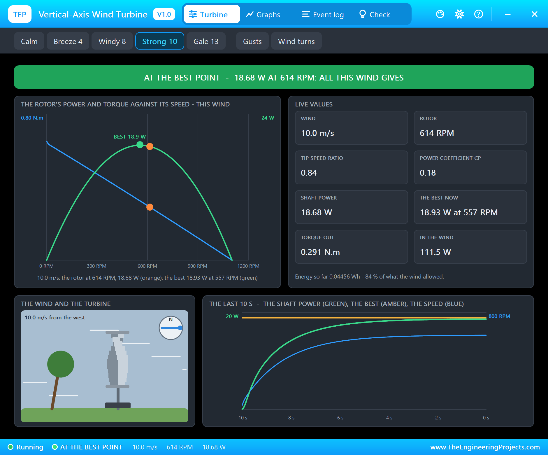
The pop-up has the look of our TEP Serial Monitor Advance for Proteus and four tabs: Turbine, Graphs, Event log and Check. The left card draws the rotor's torque (blue) and the power on its shaft (green) against its speed for the wind of the moment, with the best point in green and where the rotor really runs in orange. Below are the wind scene - the sky, the streaks, a compass showing where the wind comes from, a tree bending and the turbine turning - and the last 10 seconds of the power and the speed.
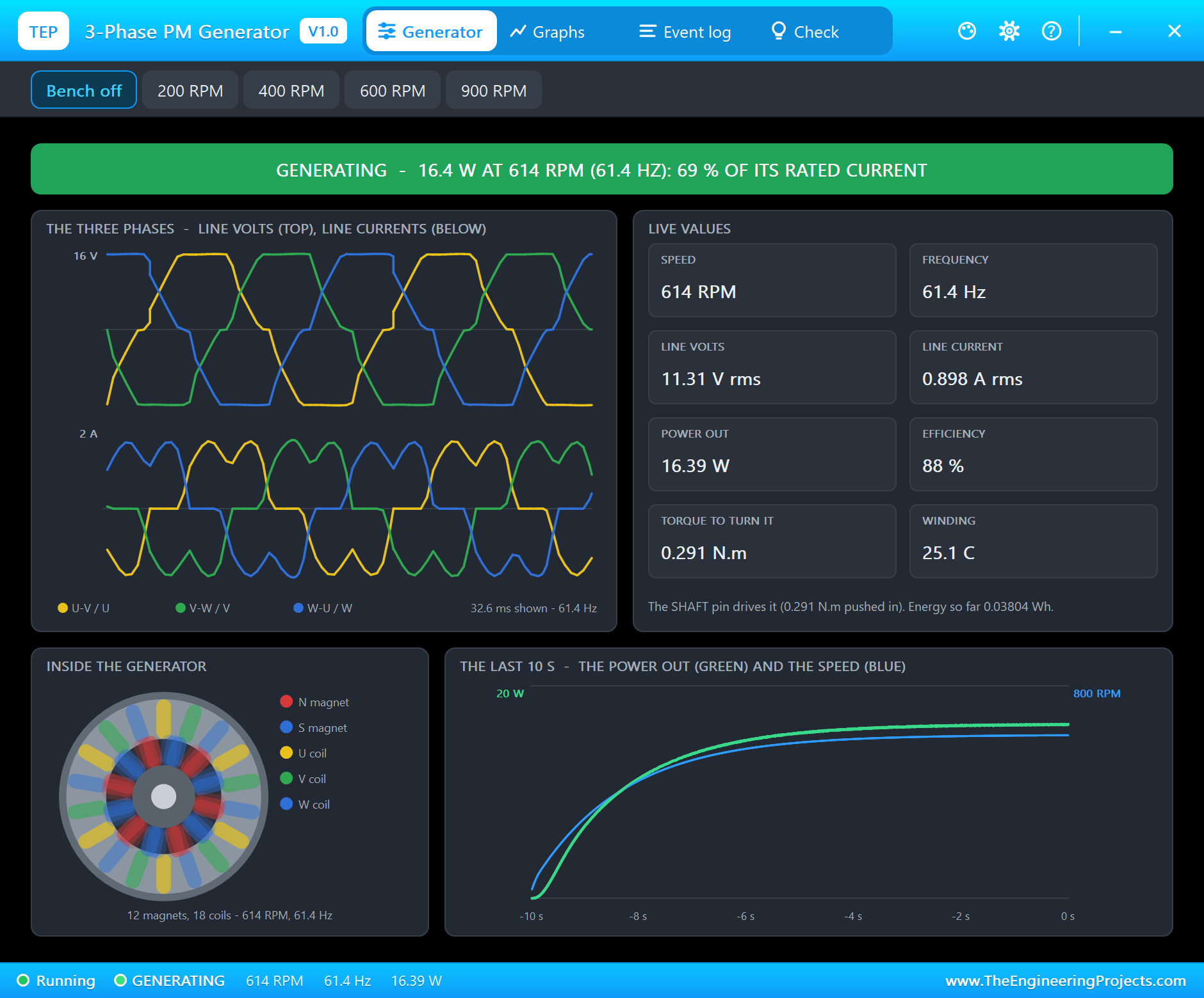
The generator's pop-up shows the same moment from the other side of the shaft: 614 RPM and 61.4 Hz, 11.31 V rms and 0.898 A rms in each line, 16.39 W out at 88 %, and "The SHAFT pin drives it (0.291 N.m pushed in)". The difference between the rotor's shaft power and the generator's power is the generator's own losses.
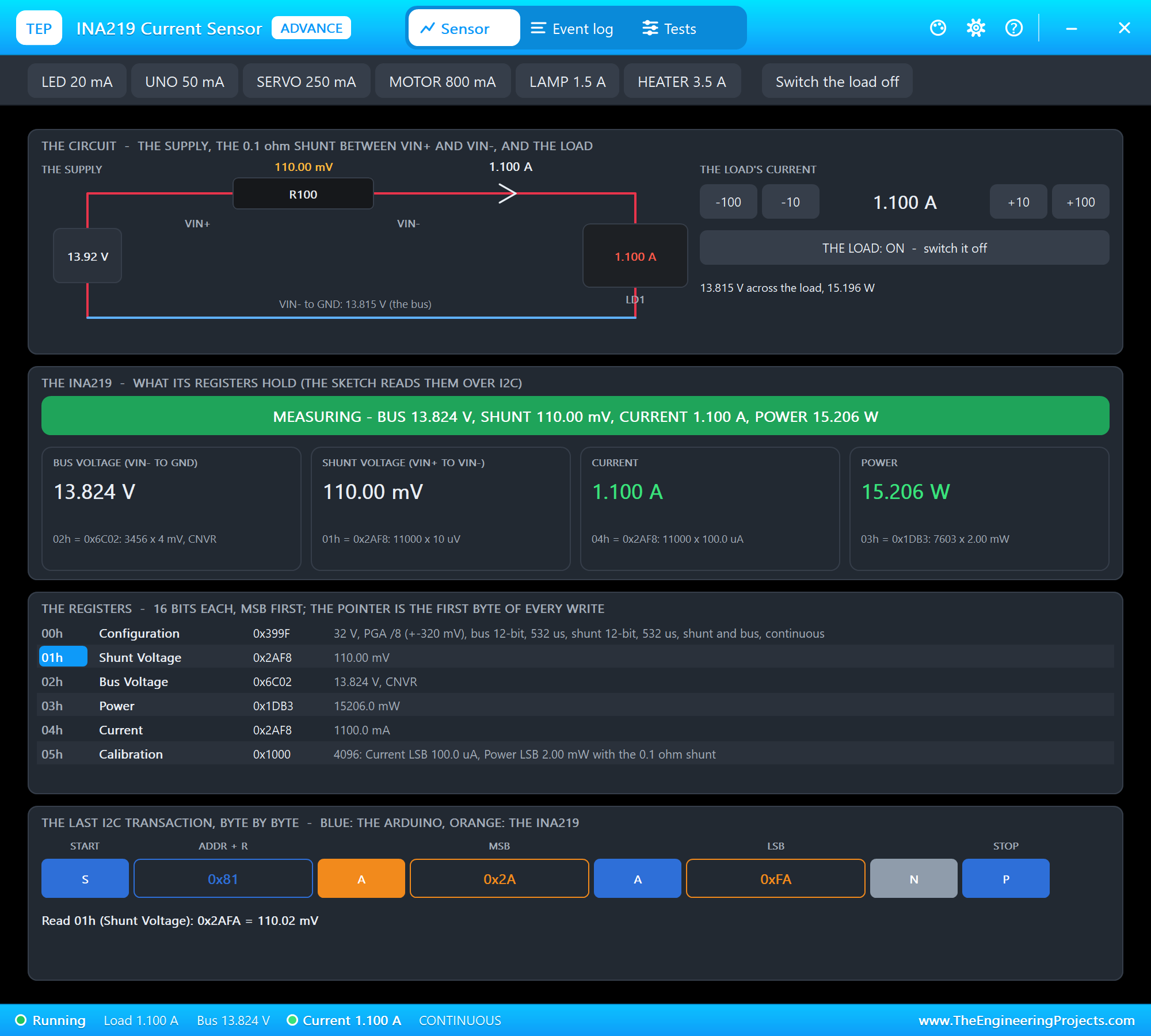
The INA219 sees what reaches the DC side: "MEASURING - BUS 13.824 V, SHUNT 110.00 mV, CURRENT 1.100 A, POWER 15.206 W" (one sample of the rippling DC; the sketch averages 16). Back at this point at the end of the run, the monitor shows the same: WT 613 RPM 61.3 Hz 13.94 V 1.100 A 15.33 W - enough for an Arduino. From the 111.5 W in the wind, the rotor takes about 19 W, and after the generator's and the rectifier's losses about 15 W reach the load.
A Light Load
Click MOTOR 800 mA on the INA219's pop-up. With less torque holding it back, the rotor speeds up past its best point: "TURNING - 737 RPM, 0.216 N.m: 16.67 W on the shaft, 88 % of the 18.93 W this wind allows (tip speed ratio 1.00)".
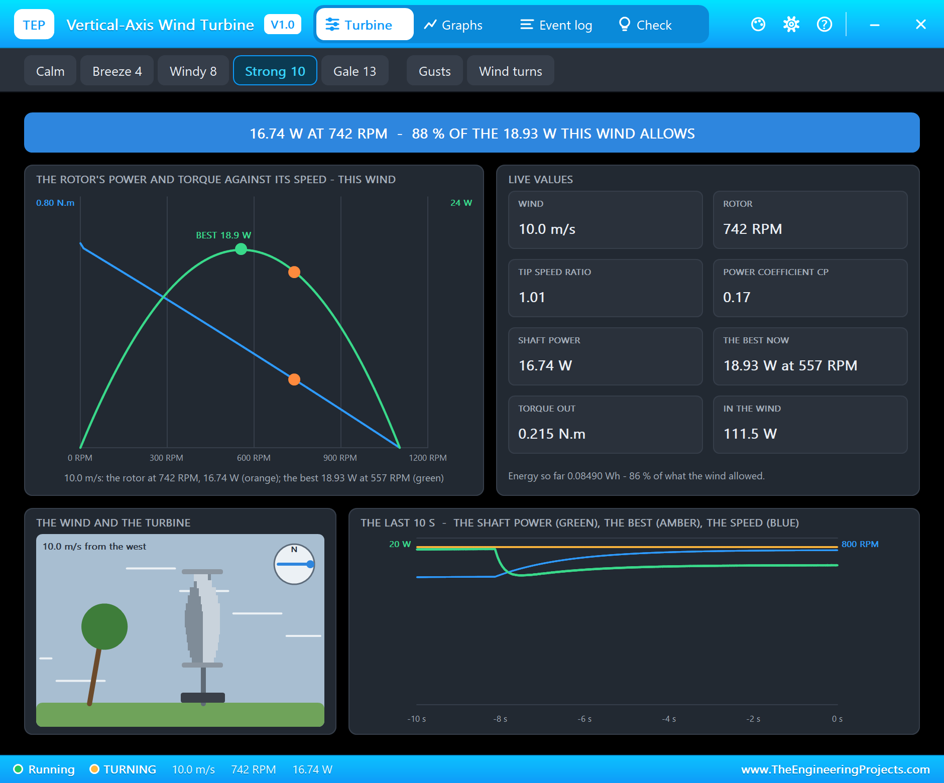
On the curves the orange point has moved to the right of the peak. A lighter load does not mean less strain on the turbine - it means the rotor wastes the wind by running too fast.
Too Heavy: a Stall
Now click HEATER 3.5 A and then -100 five times: the load wants 3 A, more torque than this wind can give. The rotor slows down and stalls: "STALLED - 10.0 m/s but only 149 RPM (tip speed ratio 0.20): the load wants more torque than this wind gives".
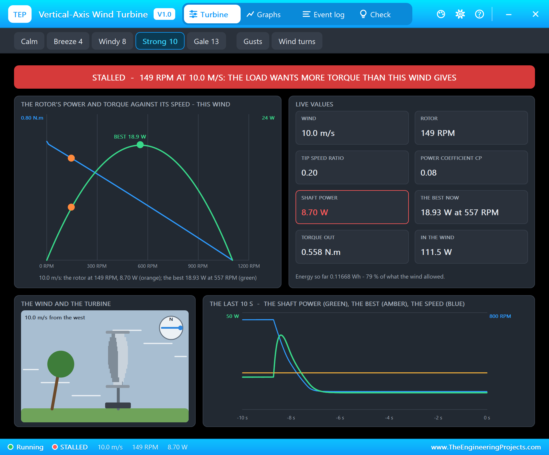
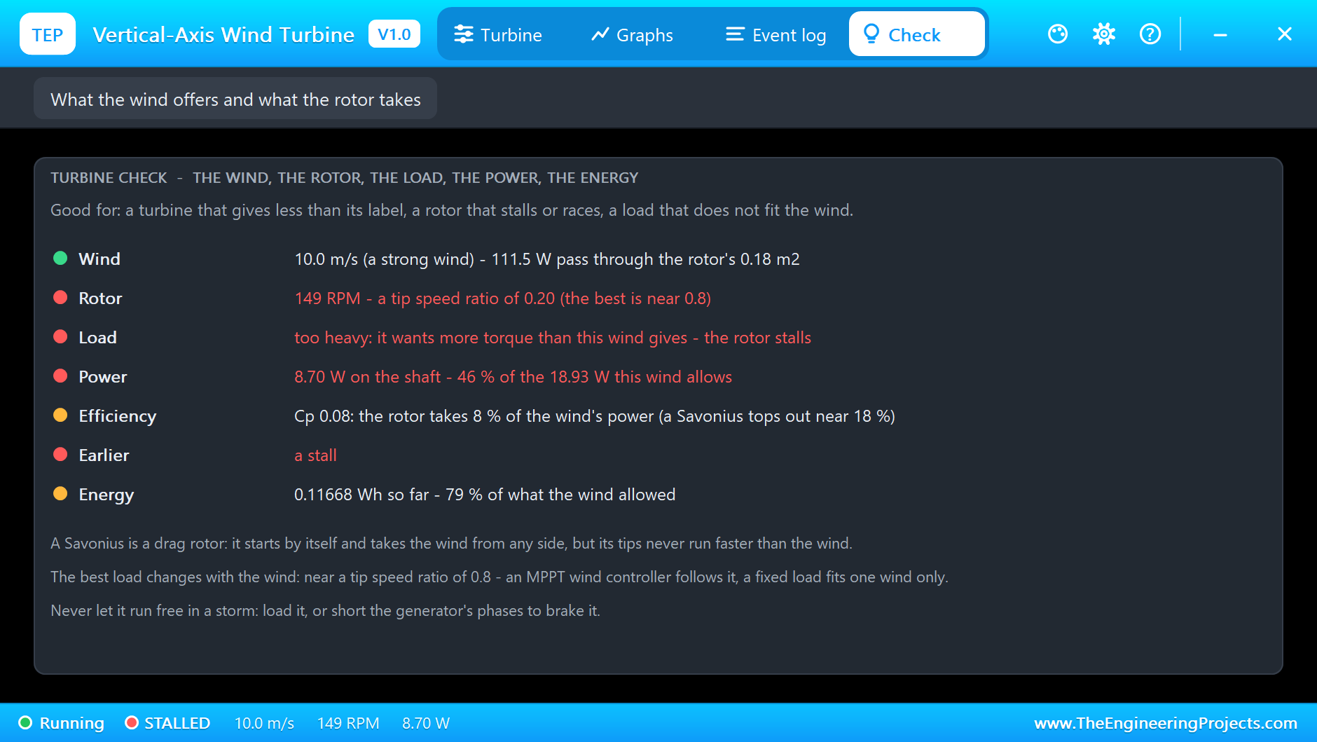
The rotor does not stop completely: an electronic load cannot sink its full current below about 0.5 V, so the current - and the generator's torque with it - falls until it matches what the wind gives at this low speed. The rectifier board now gives only 0.571 V at 2.14 A; the rest of the 8.70 W still on the shaft is lost in the generator and its diodes, and the generator's own value line reads OVERLOAD. The Check page names the problem: the Rotor, Load and Power rows turn red - "too heavy: it wants more torque than this wind gives - the rotor stalls" and "8.70 W on the shaft - 46 % of the 18.93 W this wind allows".
Back to 1.1 A (LAMP 1.5 A and -100 four times): the rotor's torque at low speed is the largest it has, so it starts again by itself and climbs back to its best point.
Less Wind
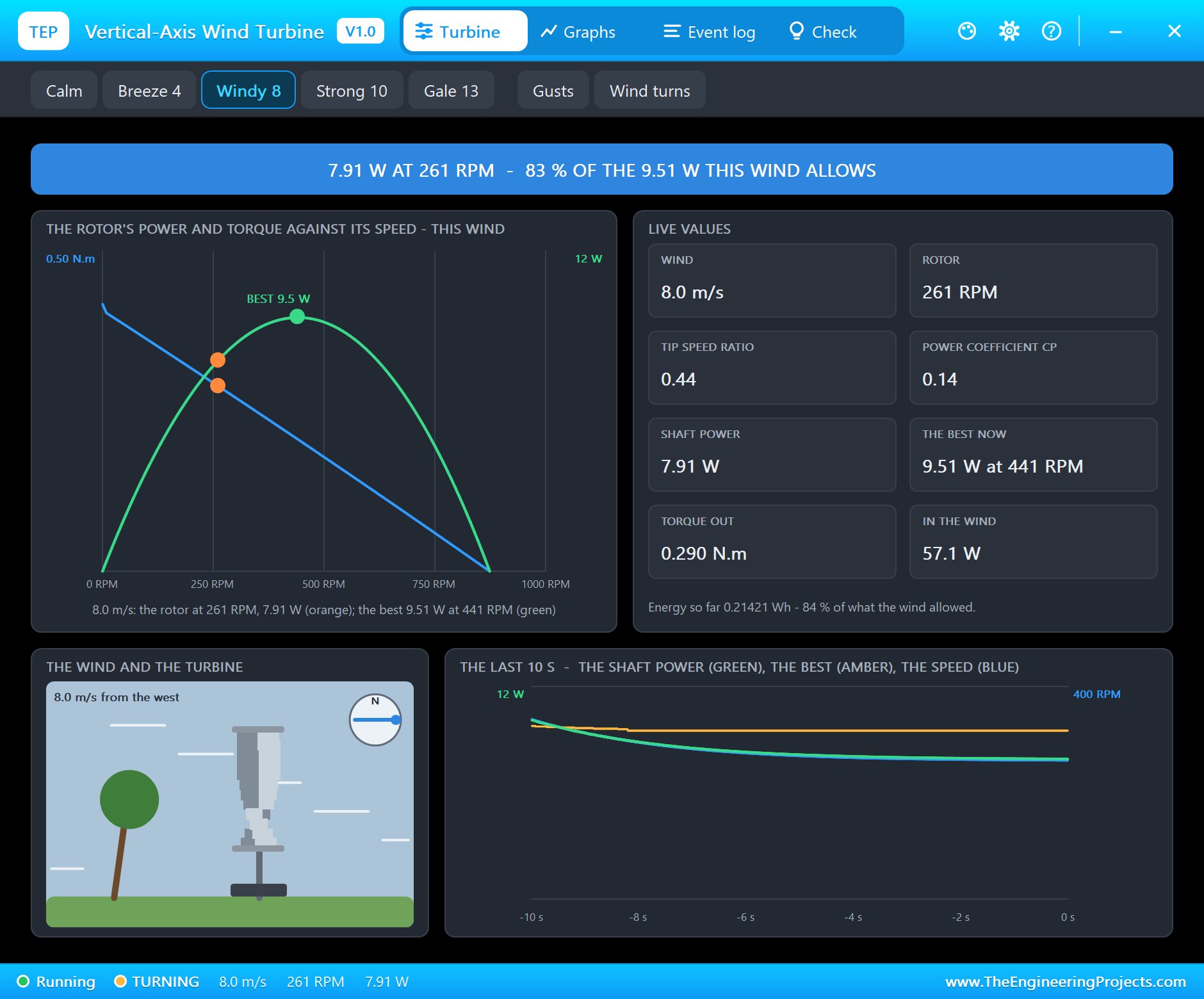
Click Windy 8 on the turbine's pop-up. The best point moves: "WIND 8.0 m/s - windy (set on the panel): the most it can give now is 9.51 W at 441 RPM". With the same 1.1 A load the rotor is now held too hard: "TURNING - 264 RPM, 0.289 N.m: 8.00 W on the shaft, 84 % of the 9.51 W this wind allows (tip speed ratio 0.45)".
Click MOTOR 800 mA: a lighter load for a lighter wind, and the rotor goes back towards its best: "AT THE BEST POINT - 417 RPM, 0.215 N.m: 9.38 W on the shaft at 8.0 m/s (tip speed ratio 0.71, Cp 0.18)".
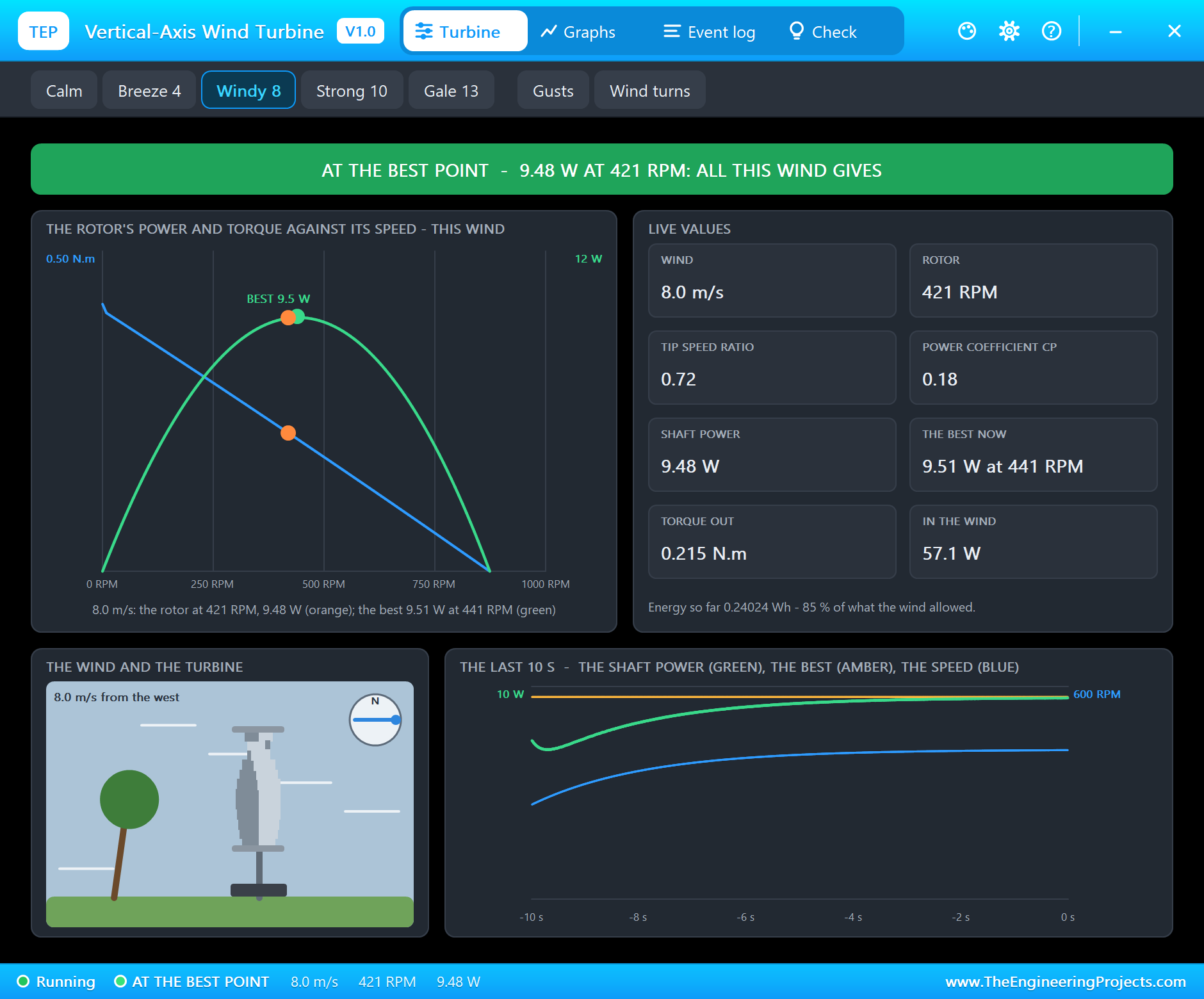
This is the whole idea of maximum power point tracking for wind: every wind has its own best load. A wind charge controller with MPPT keeps changing the load to follow the wind; a fixed load fits one wind only.
Gusts and a Turning Wind
Click Gusts and Wind turns. The wind now swings 30 % around its mean, and its direction turns round the compass: "GUSTS (set on the panel): the wind swings 30 % around its 8.0 m/s - the rotor speeds up and slows down" and "THE WIND TURNS (set on the panel), now from the west: a vertical axis takes the wind from any side - nothing to steer".
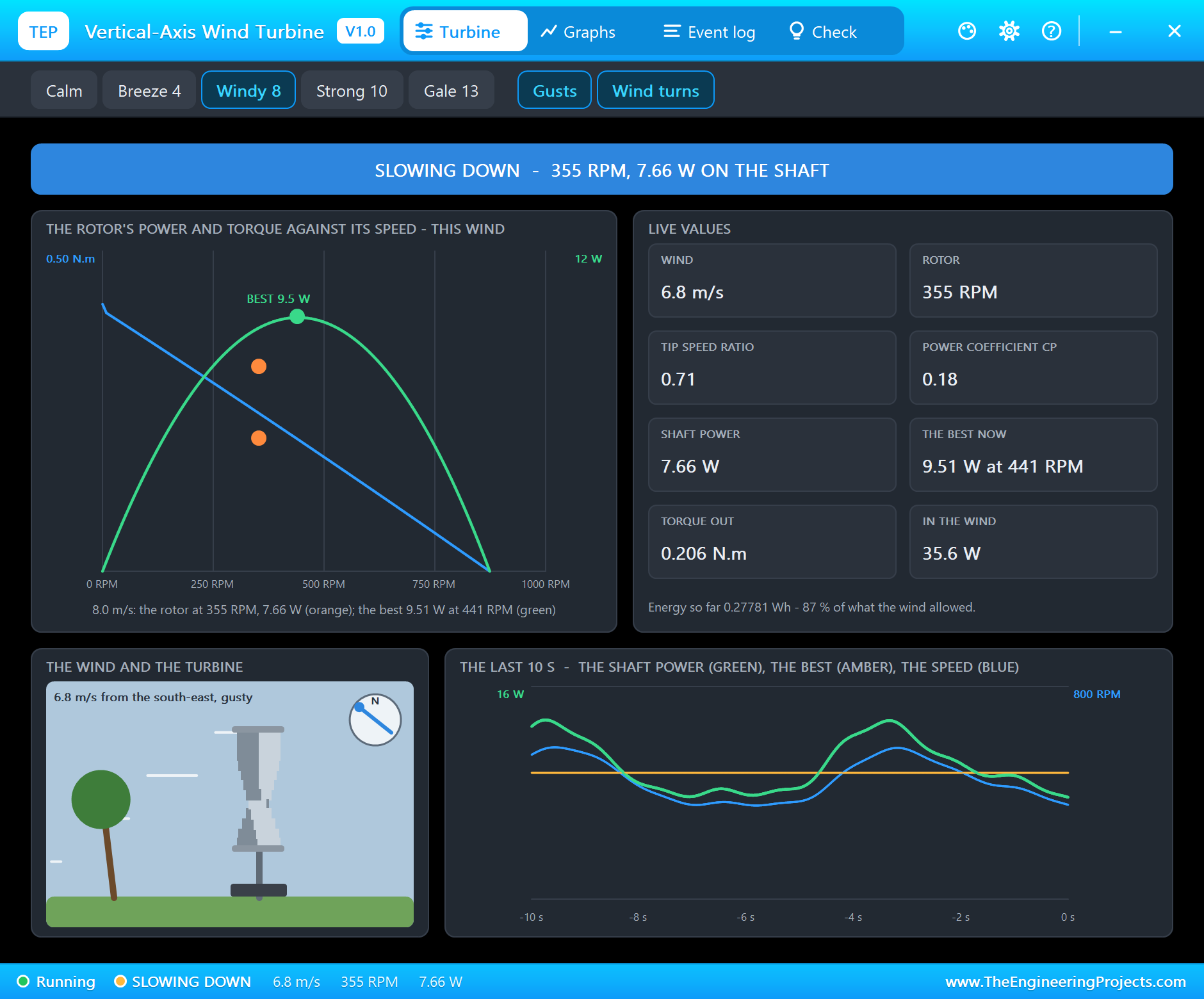
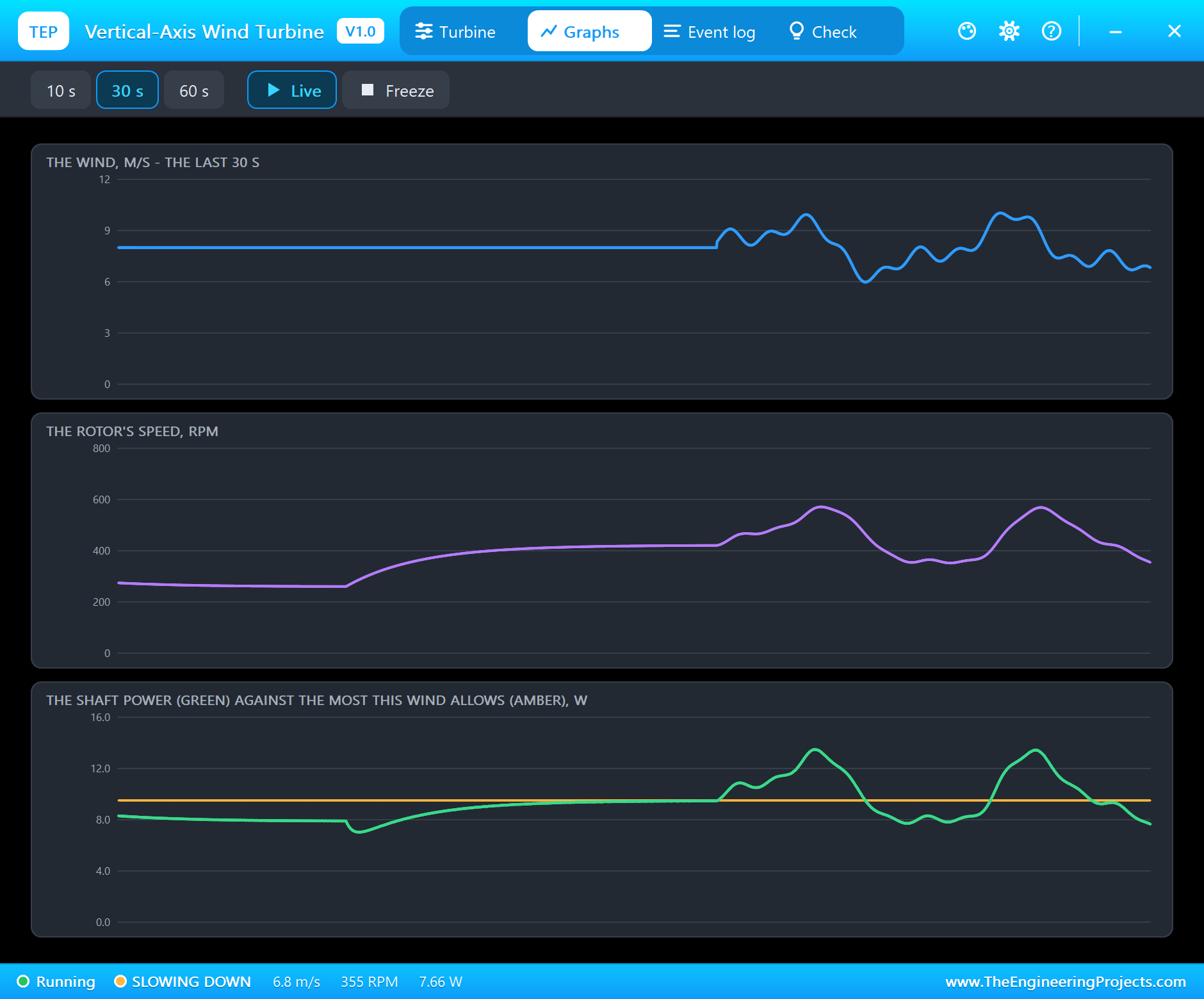
The rotor's inertia smooths the gusts a little, but the speed and the power follow the wind up and down. The direction changes nothing at all - the advantage of a vertical axis: a horizontal-axis turbine would have to turn to face each new direction. On the Graphs page the amber line is the best for the mean wind, so in the gusts the green power swings above and below it.
A Breeze and a Calm
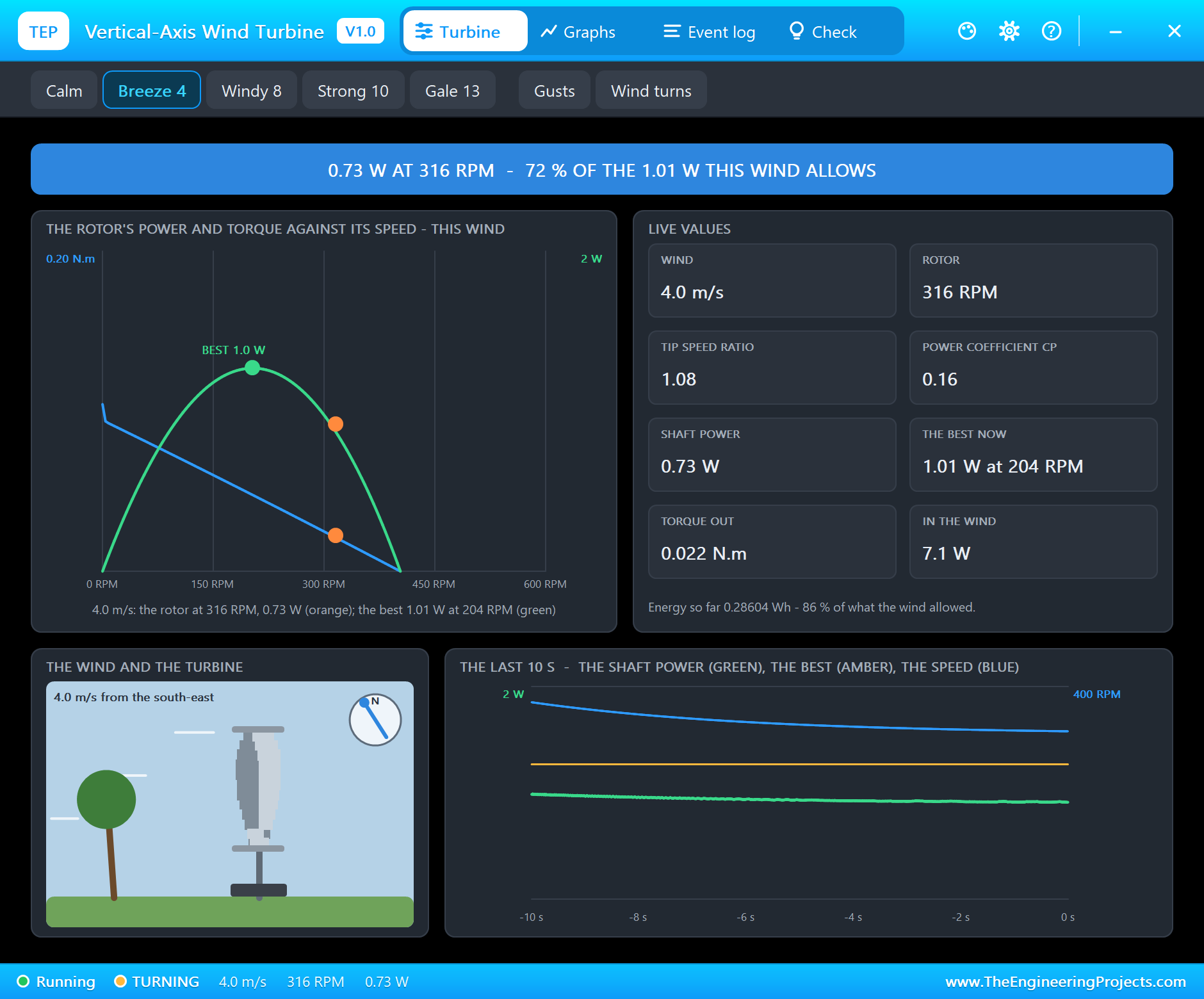
Switch the gusts and the turning off, click UNO 50 mA and Breeze 4. In a 4 m/s breeze the wind carries an eighth of the power of 8 m/s: "TURNING - 322 RPM, 0.022 N.m: 0.74 W on the shaft, 73 % of the 1.01 W this wind allows (tip speed ratio 1.10)". The rectifier board still gives 7.90 V at 50 mA - more than the 0.25 W the sketch counts as enough for an Arduino.
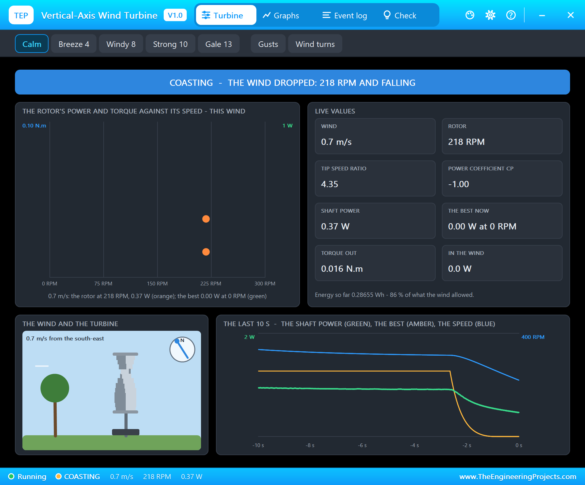
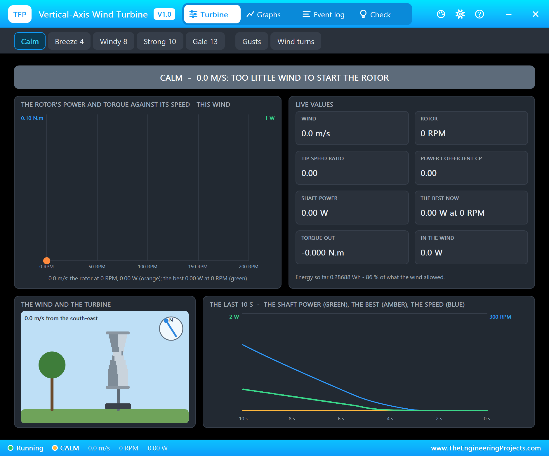
Finally click Calm. With no wind the rotor keeps turning on its own momentum for a moment: "COASTING - the wind dropped to 1.7 m/s: the rotor slows down from 275 RPM", until "CALM - 0.0 m/s: too little wind to start the rotor".
Back in a 10 m/s wind with 1.1 A, the rotor starts by itself once more, and the monitor shows the end of the story - and the best point it saw:
WT 8 RPM  0.8 Hz  0.82 V  1.100 A  0.90 W  - changing
WT 179 RPM  17.9 Hz  3.29 V  1.100 A  3.62 W  - changing
WT 305 RPM  30.5 Hz  6.34 V  1.100 A  6.97 W  - changing
WT 410 RPM  41.0 Hz  8.90 V  1.100 A  9.79 W  - enough for an Arduino
WT 485 RPM  48.5 Hz  10.76 V  1.100 A  11.84 W  - enough for an Arduino
WT 536 RPM  53.6 Hz  11.99 V  1.100 A  13.19 W  - enough for an Arduino
WT 568 RPM  56.8 Hz  12.78 V  1.100 A  14.06 W  - enough for an Arduino
WT 588 RPM  58.8 Hz  13.28 V  1.100 A  14.61 W  - enough for an Arduino
WT 599 RPM  59.9 Hz  13.55 V  1.100 A  14.90 W  - enough for an Arduino
WT 607 RPM  60.7 Hz  13.74 V  1.100 A  15.12 W  - enough for an Arduino
WT 610 RPM  61.0 Hz  13.83 V  1.100 A  15.21 W  - enough for an Arduino
WT 612 RPM  61.2 Hz  13.89 V  1.100 A  15.28 W  - enough for an Arduino
WT 613 RPM  61.3 Hz  13.94 V  1.100 A  15.33 W  - enough for an Arduino
best
Best so far: 15.34 W at 13.95 V, 1.100 A, 614 RPM
Graphs and the Log
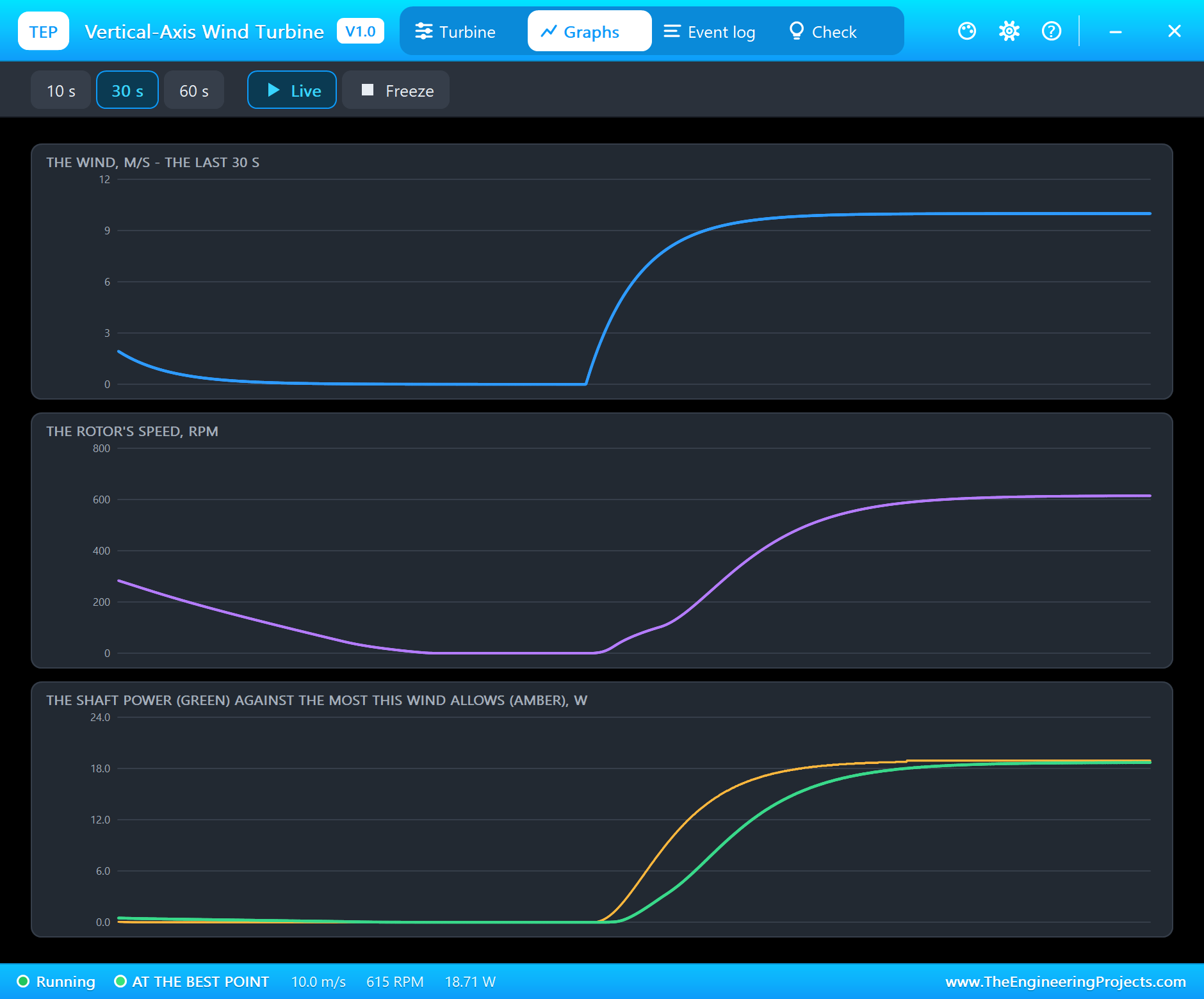
Graphs draws the wind, the rotor's speed and the shaft power against the most each wind allows, over the last 10, 30 or 60 seconds. Every gap between the green power and the amber best is a load that does not fit the wind.
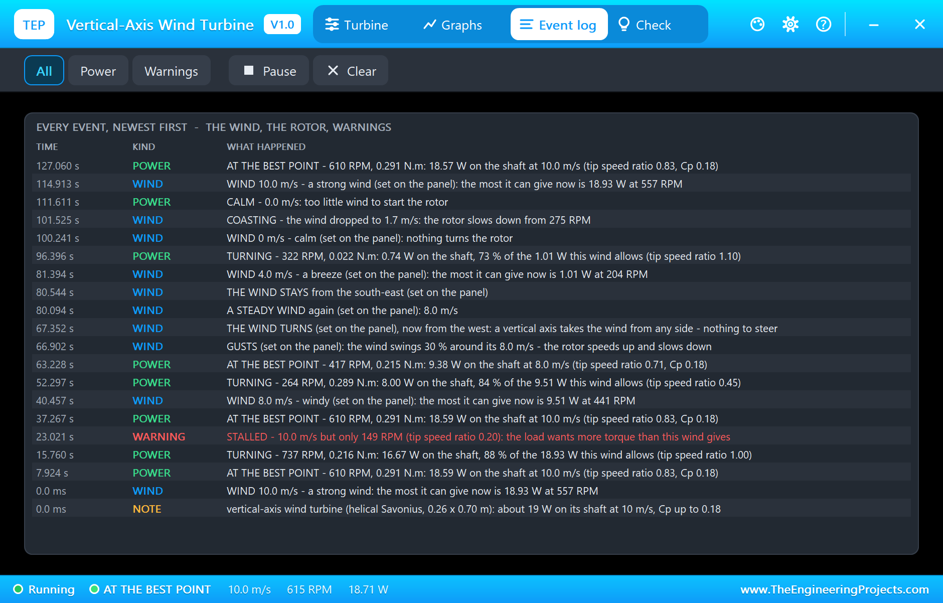
The Event log keeps every change of the wind and every steady state with its speed, torque, power and tip speed ratio. Filter it to Power or Warnings, pause it, or clear it. More warnings you may meet: RUNNING FREE when nothing takes the power and OVERSPEED above 1200 RPM, both possible in the Gale 13 wind with the load switched off.
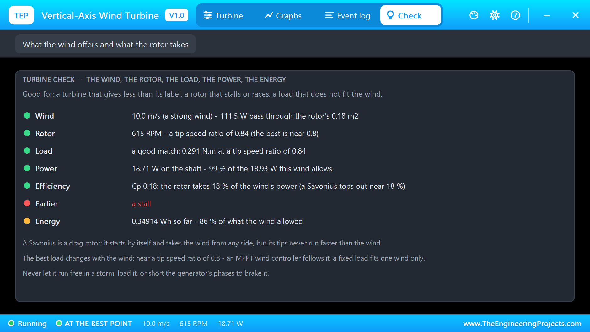
At the end of the run the Check page sums it up: the Power row reads "18.71 W on the shaft - 99 % of the 18.93 W this wind allows", the Efficiency row "Cp 0.18: the rotor takes 18 % of the wind's power (a Savonius tops out near 18 %)" and the Energy row "0.34914 Wh so far - 86 % of what the wind allowed" - the stall and the gentle winds cost the rest. It also remembers the stall from earlier.
How the Model Works
The rotor's torque coefficient falls in a straight line with the tip speed ratio, from 0.45 at standstill to nothing at 1.6. Its torque is 1/2 rho A R Cq v^2, which turns out to be linear in the rotor's speed - so at every Newton step of the simulation the model puts it into the SHAFT net exactly, as a current and a conductance. The bearings, the gearbox and the air's drag on the spinning buckets are there as their tangent, and the rotor's inertia as a capacitor on the net.
The generator on the same net takes the torque its load needs, so the wind, the rotor, the generator, the rectifier and the load are all solved together - nothing is calculated "outside" the circuit. The wind follows a new value over about a second and a half, and gusts are a sum of three slow waves.
We tested the model on a PC before Proteus: 10 checks of the rotor alone and of the rotor driving the generator, the rectifier and the DC load. They found the best DC load at 10 m/s at 1.1 A (15.34 W), a stall at 8 m/s with 3 A, no start at 1 m/s, and gusts at 8 m/s that swing the rotor between 351 and 609 RPM without ever stalling it.
Troubleshooting
- CALM: too little wind to start the rotor - about 1.7 m/s with the generator on it.
- STALLED: the load wants more torque than this wind gives - lighten the load or wait for more wind.
- RUNNING FREE: nothing takes the power - check the shaft wire, the generator and its load.
- OVERSPEED: over 1200 RPM - load it more or brake it.
- The turbine is not simulated:
TEPVAWT.DLLis missing from MODELS and from the project folder. - No generator or no rectifier board: install our 3-Phase PM Generator library.
- No INA219 or no load: install our INA219 library.
- The buckets do not seem to move: the part is repainted at most four times a second; when the rotor is fast it is shown turning steadily forwards.
- No pop-up: click OPEN PANEL on the gearbox, or turn "Open the panel at Run" on in its Settings.
Things to Know Before Building a Real VAWT
- Mount it high and clear: the wind near roofs and trees is slow and turbulent, and the power grows with the cube of the wind speed.
- Expect a modest power coefficient: a Savonius gives a Cp near 0.15 to 0.2 - safe, quiet and self-starting, but a Darrieus or a horizontal-axis turbine of the same size gives more in a steady wind.
- Match the load to the wind: a wind charge controller with MPPT follows the best point; a fixed load fits one wind only.
- Never let it run free in a storm: keep it loaded, or short the generator's phases to brake it.
- Balance the rotor: a helical rotor at several hundred RPM shakes a light mast.
Limitations of the Simulation
- Not modelled: the torque's ripple as the buckets turn (a helical rotor smooths it), the wind's shear and turbulence beyond the gusts, the mast's shadow, icing, and the structure's vibration.
- The value line, the OUT LED and the OPEN PANEL button are TEP additions.
- The model is our own, fitted to the typical data of small helical Savonius rotors; this library is not made or endorsed by any turbine maker, Arduino or Labcenter.
- Licences: the demo HEX contains the Arduino AVR core 1.8.6 (LGPL) with its Wire library; the sketch is included and the README gives the source link. The generator, the rectifier board, the INA219 and the DC load of the demo are our separate libraries.
- Tested in Proteus 8.5 in October 2026 with the demo as shipped: the best point, a light load, a stall, 8 m/s with two loads, gusts and a turning wind, a breeze, a calm, and all four pages of the pop-up. Proteus 7 is not supported.
So, that was all about the Vertical-Axis Wind Turbine Library for Proteus V1.0. Together with the 3-Phase PM Generator Library for Proteus, it simulates a small wind power system from the wind to the DC side. If you have any questions, ask in the comments and I will help you out. Till the next tutorial, take care and have fun!