ECG Averaging in MATLAB
Buy This Project
Hello friends, I hope you are doing great. Today, I am going to share an expert level project which is ECG Averaging in MATLAB. If you are new to ECG then you should have a look at
Introduction to ECG. I have already shared
ECG Simulation using MATLAB in which we have seen how to simulate an ECG signal and then diagnose heart disease. We have also extracted ECG features in that project. So, if you guys haven't read that tutorial then I would suggest you to not read this one. First read
ECG Simulation using MATLAB and then you should read this tutorial. Today's project is quite an extension of our previous project ECG Simulation using MATLAB. Our team has designed this project after quite a lot of effort that's why its not free to use but you can easily buy it from our shop using PayPal, by clicking the above button.
In today's tutorial, we are gonna have a look at How to do ECG Averaging in MATLAB. ECG Signals normally have a lot of noise in them that's why its quite necessary sometimes to average the ECG signal so that we get better results. That's where ECG averaging is required. So, lets get started with ECG Averaging in MATLAB.
ECG Averaging in MATLAB
- Let me first explain in detail why we need to average an ECG signal and how we are gonna do that.
- Check ECG signal shown in below figure:
- In the above ECG signal, we can see there's a lot of noise in ECG waveform, which may affect our results so there's a need to apply some filters to smoothen out the ECG waveform.
- Another way of removing noise is ECG averaging.
- In ECG averaging technique, we cut signle ECG signal and then we extract all of our peaks.
- Finally we add them up and create an average waveform.
- I have shown this whole procedure in below figure:
- In the above figure, you pretty much got the idea behind this project.
- Now here's its MATLAB GUI, shown in below figure:
- It has two Containers at top and a full length Graph at the bottom.
- Now, when you Click the Button the it will ask for the ECG data file, as shown in below figure.
- Currently this project has eight data files with it and I have tested all of them and they are working quite fine.
- I have downloaded all the data files from Phsio Bank website. You can read its more details in ECG Simulation using MATLAB.
- Now when you will upload the files then it will take all the peaks and then will add them up one by one and will give you final output in the right container.
- The whole procedure for data1 is shown in below figure:
- I hope now you got the complete idea of its working but still if you have any questions then you can ask in comments and I will help you out.
- Here's the final look of this project:
- I have also created this video in which I have explained it in more detail and shown how it works.
- So, if you wanna buy this Project then I would suggest you to must watch this video before so that you got the complete idea of what you are buying.
- Here's the video for ECG Averaging in MATLAB:
So, that's all for today. I hope you have enjoyed today's tutorial. Will see you guys in next tutorial. Till then take care and have fun !!! :)
Heart Beat Sensor Library for Proteus
Hello everyone, I hope you all are doing great. Today, I am going to share a new Heart Beat Sensor Library for Proteus. Using this Library, now you can easily simulate your Heart Beat Sensor in Proteus ISIS. I am quite excited while sharing this Library as it has never been designed before. All credit goes to the TEP team for creating this awesome Heart Beat Sensor Library for Proteus. You should also have a look at this Second Version of Heart Beat Sensor Library for Proteus.
Heart Beat Sensor is used to measure the Heart Beat Count of a person. When you are using a Heart Beat Sensor in hardware then there's a chance that you won't get the same results as this simulation because the placement of a finger on this sensor matters a lot. If you haven't placed your finger correctly then you may get different results. This Proteus Sensor will give you the ideal result means the finger is perfectly placed on the sensor. So, let's get started with Heart Beat Sensor Library for Proteus:
Heart Beat Sensor Library for Proteus
- First of all, you need to download this Heart Beat Sensor Library for Proteus by clicking the below button:
Heart Beat Sensor Library for Proteus
- Download this zip file and then open it.
- You will find three files in it named:
- HeartBeatSensorTEP.IDX
- HeartBeatSensorTEP.LIB
- HeartBeatSensorTEP.HEX
- Place all these three files in the Library folder of your Proteus Software.
Note:
- If you are using Proteus 7 Professional, then the library folder link will be something like this: C:Program Files (x86)Labcenter ElectronicsProteus 7 ProfessionalLIBRARY
- If you are using Proteus 8 Professional, then the library folder link will be something like this: C:ProgramDataLabcenter ElectronicsProteus 8 ProfessionalDataLIBRARY
- You should also have a look at Heat Beat Sensor Library V2.0 for Proteus.
- Now open your Proteus software or restart it, if it's already running.
- Search for Heart Beat Sensor in the components section, as shown in the below figure:
- Now select this sensor and place it in your Proteus workspace.
- If everything goes fine then you will get something as shown in the below figure:
- How it looks ?? Do let me know in the comments. Btw I think it looks pretty cool. :)
- So, now you can see in the above figure that it has in total four pins.
- TestPin is just for the simulation, it's not present in the real Heart Beat Sensor.
- In Proteus, we can't actually place our finger on this sensor, that's why I have added this TestPin.
- If TestPin is HIGH, it means that the finger is placed on the Sensor and it will start counting the heart beat.
- If TestPin is LOW, then it means the finger is not placed on the sensor and it won't give the output and will remain silent.
- The remaining three pins are simply GND, Vcc and OUT pins.
- Now, we need to upload the Hex file in this Heart Beat Sensor, so double-click it and open its Properties section as shown in the below figure:
- In the above figure, you can see first of all you have to click on the Program File Section and then you need to Browse to the Hex File of Heart Beat Sensor, which we have just downloaded above and placed in the Library folder of Proteus software.
- Now your Heart Beat Sensor is ready to simulate in Proteus software, so let's simulate it in Proteus:
Heart Beat Sensor Simulation in Proteus
- First of all, design a small circuit as shown in the below figure:
- Now, run your simulation and if everything goes fine then you will get the results as shown in the below figure:
- You can see in the above figure that OUT Pin is toggling, the HIGH & LOW states of OUT Pin are actually simulating the heart beat.
- Now you can easily count it for some period of time and then can display your heart beat.
- I have also explained its working, in the below video:
So, that's all for today. I hope you have enjoyed this awesome Heart Beat Sensor Library for Proteus. Let me know about your feedback in the comments. Till next tutorial, take care and have fun !!! :)
C# Label Control
Hello everyone, I hope you all are doing great. In today's article, I will guide you about the C# Label Control. I will show you how to deal with label in C Sharp Programming Language. Labels have their own importance in the software development to nominate the input and output fields. You have observed that every software which you have used and with you are familiar have some labels. Such as in the website login forms there are labels too. It's recommended to use the labels in the software to make the user interface rich with the helping material. If you will just use the C# Button, C# TextBox, and C# ComboBox and don't use the C# Labels then your developed software will not be easy to use. In simple words, it won't be user-friendly. So, in order to make it user-friendly, we have to use Labels in our software. So, let's have a look at How to use C# Label Control and How to change its Properties:
C# Label Control
- We used the C# Label to display the text on the software to give direction for the user.
- Label control is also used to show the descriptive text such as the notes and warning about the usage of the software.
- To define the label in C# you have to declare namespace as follows.
System.Windows.Forms
- You can also add the label from the toolbox and drag the label from the form designer tab.
- Label1 is the default Name of the very first label which you will use in your application.
- You can adjust the size on the form by stretch the coordinates.
- You can change the text from the right panel under the property label.
- You can also change the text using the below code:
label1.Text = "TEP C# Label Control Example Text";
- Here's the output of this code:
- You can do anything with the label box. There are many properties which you can use to manipulate the functionality of simple label.
- For example, if you want to change the background color of the label then you need to use BackColor property.
- BackColor Property is used to change the background color, after the equal (=) sign you have to declare that you want to change color by writing the property Color and after dot, you have to write the name of the color which you want to allocate to the background
- In the below code I have declared the Aqua color for the background, there are many colors which you can be used for the background of the label.
label1.BackColor = Color.Aqua;
- Here's the output of above code:
- If you want to change the foreground color or the color of text, then you need to use ForeColor Property.
- ForeColor is the name of the property which is used to assign the color of the text in the label.
- Here's the code for it:
label1.ForeColor = Color.BlueViolet;
- If you want to set the images as the background of C# label then need to use below code:
label1.Image = Image.FromFile("C:\\Users\\Jade\\Pictures\\brownImage.jpg");
- Image property is used to set the image. You have to use the Image.FormFile method to set the proper path of an image which you want to set.
- In double quotation write the path and used "\\" to separate the directories, you have to mention the image with the extension. It will generate the following results.
C# Label Events
Let's do some advanced code to improve the interaction level of your application. Now let's study the builtin events which we can apply on our C# Label to improve its functionality. Events are created to perform some functionalities when user will do any specific task. There are several Events which you can use to implement on your label, here are the few of them:
- Click Event
- Double Click Event
- Text Changed Event
- MouseHover Event
- MouseLeave Event
There are several more events which we can use, but the main task here is to just give you the basic concept of C# Label. That's why we will focus on most commonly used events.
C# Label Click Event
- The first event is the Click Event, which will perform when user will click on the label.
- Let me give you an example, suppose you need to create a program in which you want to surprise someone, so now when someone click on your software then a hidden message shows up. It could be Happy Birthday !! ;)
- Here's the code for it, you can change the text to anything you want.
private void label1_Click(object sender, EventArgs e)
        {
            label1.Text = "Text Changed";
        }
- After the default name, you have to write the _Click and create the method and declare the functionality which you want to perform.
- You can do any kind of manipulation inside click event.
C# Label Double Click Event
- This event will occur when user will click twice on the label.
- Here's the code for it:
 private void label1_DoubleClick(object sender, EventArgs e)
        {
            label1.Text = "Text Changed";
        }
- After the default name, you have to write _DoubleClick method and declare the functionality which you want to perform. It will occur when user will click twice on the label.
C# Label Text Changed Event
- This event will occur when the text of the label is changed.
- Suppose you want to change any value on the application when the text of the label is changed. Then you will use the TextChanged Event.
- Let me explain it with an example, I have taken two labels.
- Now the logic is when the text of one label is changed then the other label text should change automatically.
- For the first label, I will use the _Click Event and _TextChanged Event too.
- So, now when user will click on the label, the text of label will change because of _Click Event
- Now, when text is changed, _TextChanged Event will occur and 2nd label text will also change.
- Here's the code which you should try.
private void label1_Click(object sender, EventArgs e)
        {
            label1.Text = "Text Changed";
        }


        private void label1_TextChanged(object sender, EventArgs e)
        {
            label2.Text = "2nd Text Changed";

        }
- To test the above code you have to drag two labels on your application. Then copy the above code into your application.
C# Label MouseHover Event
- This event will occur when user will hover the mouse cursor on the label.
- Suppose you want to change the text when user will hover the mouse cursor on the label.
- Here's the code for it:
private void label1_MouseHover(object sender, EventArgs e)
        {
            label1.Text = "Text Changed";
        }
C# Label MouseLeave Event
- This event will occur when the cursor will leave the label.
- Suppose you want to change the text of label when mouse cursor will leave the label.
- Here is the code, which will perform this functionality:
private void label1_MouseLeave(object sender, EventArgs e)
        {
            label1.Text = "again Text Changed";
        }
- By the combination of the above events and methods, you can create your own C# applications with multiple functionalities.
If you are looking to learn more about the C# label control and other features of the C# programming language than you should subscribe our YouTube channel where we have uploaded latest tutorials on C#. Thanks for reading, have a good day !!! :)
C# TextBox Control
Hello everyone, I hope you are doing great. In this article, we will talk about C# TextBox Control. In the previous articles, you have already get familiar with C# Button Control & C# Label Control, this is the sequence of those. In short C# TextBox Control is just same as the other expect some few changing. Before getting started with C# TextBox you must have knowledge of previous concepts. It's not essential but it will give you the edge to understand the advanced elements of C#.
C# TextBox is used to get input from users or it can also be used to display some values to the user. The textbox is a container for text blocks, you can take inputs or show the text as you required in the form of paragraphs. If you used TextBox as the input field then you can only take one line of text as the input but if you want multiple line input then you have to activate the multiple line property of C# TextBox.
You can also change your input field as the password field if you are using the TextBox for password. A user can write input in the textbox and the even user can simply paste the data too in the field. You can also add some advance features like grabbing the copied data automatically when user hover the mouse on the input field, it will be done by accessing the clipboard where the copied data is saved temporarily, but this is the advance feature which we will cover after the basics. So, now let me show you how to use C# TextBox:
C# TextBox Control
- First of all, you have to drag the TextBox from the toolbox and adjust it on your application form as you wanted.
- The Default Name of textbox is 'textbox1' which you can change from the right panel under the property tab.
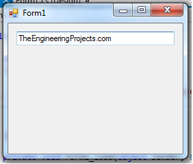
- You can also change the Text Property inside of the textbox from the property panel, but if you want to change the text runtime or dynamically then you have to code like below.
textBox1.Text = "TheEngineeringProjects.com";
- In the above code, it's clearly mentioned that I have declared the Text property as "TheEngineeringProjects.com".
- Now when you will execute the code, a textbox will appear with the text automatically, as shown in below figure:
- You can also give the value of the textbox with the help of variables, like store the string in any variable and then passed to the textbox. Code is given below:
string var = "TheEngineeringProjects.com";
textBox1.Text = var;
- Till now we have seen How to input value into textbox, now we are gonna have a look at how to extract value from textbox.
- If you want to extract the value from textbox then you have to use below code:
string var;
var = textBox1.Text;
- By using the above code, you can easily store the value of textbox into any variable and make it reusable for the whole application.
- You can set the textbox properties with the help of property panel too.
- If you want to modify the textbox from property panel then the shortcut for that is F4.
- If you want to change the textbox height and width dynamically then you have to use the below code.
- One more thing, you can also change its dimensions from the designer tab by just dragging the coordinates of textbox.
textBox1.Width = 250;
textBox1.Height = 50;
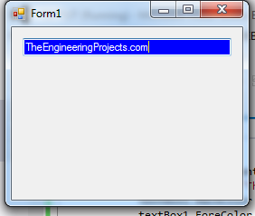
- If you want to change the background color, then below code will help you out:
textBox1.BackColor = Color.Blue;
- If you want to change the foreground color, then here's the code for it:
textBox1.ForeColor = Color.White;
- Now when you apply these codes then you will get something as shown in below figure:
- Now let's have a look at few of its Border styles.
- There are three types of the border which you can apply.
- FixedSingle.
- Fixed3d.
- None.
- If you want to change the border style for textbox then you have to use below codes:
textBox1.BorderStyle = BorderStyle.Fixed3D;
textBox1.BorderStyle = BorderStyle.FixedSingle;
textBox1.BorderStyle = BorderStyle.None;
- Till now we have seen different Properties of C# TextBox, now let's check out few of the events associated with it.
- Few of these events are keydown or keypress events.
- In the below code, I have captured the keystroke from the user and after that I have placed a check for the ENTER keystroke.
- So, whenever you press ENTER in C# TextBox then a Message Box will open up showing "You Pressed Enter".
private void textBox1_keydown(object sender, KeyEventArgs e)
{
   if(e.KeyCode == Keys.Enter)
   {
      MessageBox.Show("You Pressed Enter");
   }
}
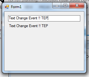
- You can also add some advanced features too like text change event which will occur when user will change the default text.
private void textBox1_TextChanged(object sender, EventArgs e)
{
      label1.Text = textBox1.Text;
}
- If you want to set the maximum length of the text inside textbox then you can also handle this with max length property like below code.
textBox1.MaxLength = 40;
- Sometimes you have to fix the textbox so that user can't add the value, in short, to make the textbox disable from the input. For this, you have to activate the ReadOnly property as true.
textBox1.ReadOnly = true;
- In the beginning, I have declared that you can make your text box as the multiline textbox for that you have to activate the multiline property as the following code do.
textBox1.Multiline = true;
- If you want your textbox as the password type input field then you have to make the characters as the password using below code.
textBox1.PasswordChar = '*';
- If you want to make your textbox like whenever the user enters any data it will start from the newline then there are two ways to do it, I'm sharing both the codes:
//First Method
textBox1.Text += "your text" + "\r\n";

//Second Method
textBox1.Text += "your text" + Environment.NewLine;
- Sometimes we use textbox only for integer values, but when the user adds an integer value in the textbox it will consider as the string by default, so we have to convert that into the integer. It's the major concept for which beginners are searching. Here in the below code, you will get the basic idea how to retrieve the integer value from the textbox input.
int i;
i = int.Parse (textBox1.Text);
- First, we have taken an integral type variable and then parsed the textbox value through integer. Now, we will parse the textbox with float and double using below code:
//String to Float conversion

		float  i;
		i = float.Parse (textBox1.Text);
//String to Double conversion

		double   i;
		i = float.Parse (textBox1.Text);
- Here we have done with our C# TextBox Control, and elaborate almost every property which we need in daily software development routine.
- If you practice these properties than you will become able to create your own small calculators and inventory systems.
- For just conclusion, I'm going to recap all the properties in one chunk of code given below:
using System;
using System.Drawing;
using System.Windows.Forms;

namespace WindowsFormsApplication1
{
    public partial class Form1 : Form
    {
        public Form1()
        {
            InitializeComponent();
        }

        private void Form1_Load(object sender, EventArgs e)
        {
            textBox1.Width = 250;
            textBox1.Height = 50;
            textBox1.Multiline = true;
            textBox1.BackColor = Color.Blue;
            textBox1.ForeColor = Color.White;
            textBox1.BorderStyle = BorderStyle.Fixed3D;
        }

        private void button1_Click(object sender, EventArgs e)
        {
            string var;
            var = textBox1.Text;
            MessageBox.Show(var);
        }
    }
}
- You need to drag the textbox and button on your form and then copy the code.
- When you will execute this code, it will demand any input from you and when you will enter and press the button it will show you the popup message box in which the input text appears.
- Here's the video which will help you better in understanding C# TextBox control:
So, that's all for today. I hope you have enjoyed today's tutorial on C# TextBox. I will share more tutorials on C# soon. If you have any questions regarding today's tutorial then you can as in comments. Thanks and take care !!! :)
C# ComboBox Control
Hey everyone how are you, hope you are doing great. In this article I will guide you about the C# comboBox. In my previous article, I have explained about C# button control and their features. C# ComboBox is quite similar to button control but its major properties are different. The combo box can hold multiple values at the same time, it's like drop-down box in appearance and you can select any value inside it. Most of the time, combo box is used to give the user multiple selection options. But in signup forms, it's used for country selection where you have to select your country from drop down. You can use combo box according to your requirements.
You can add the combo box from the toolbar and drag it on the form. When you drag that you can set the height and width by just moving the coordinates of combo box field. In other words, ComboBox is a combination of textbox and list box to show the list data as the text.So,now let's have a look at How to control C# ComboBox:
C# ComboBox Control
- As I have mentioned earlier, drag your ComboBox from the toolbar and drag it on the Main Form.
- If you have dragged the C# comboBox then add the following code in the main function to add the demo values in your C# combobox list.
- By using the following code, you can easily insert the values in your combobox, you can do it manually or you can take inputs from the C# TextBox too, it all depends on the situation and development scheme.
comboBox1.Items.Add("The");
comboBox1.Items.Add("Engineering");
comboBox1.Items.Add("Projects");
- Here's the screenshot of our C# ComboBox having three items which I have inserted using above c# code:
- ComboBox1 is the default name of the first combo box which you will drag on the windows form. You can change this name from the property panel which is on the right side. Even that you can insert the values from that too inside the combo box.
- Every value which you want to insert is considered as an item. You have observed in the above code we used the default.items.add("DataValue") this is the basic syntax for insertion and CRUD is also applied by this syntax.
- Now move on some advanced techniques which you can be used to make your application more interactive. Like you can be retrieved the selected items from the combo box as the value or input. You just have to take the string type variable and passed the selected item's value to it, you can do this by the following code.
var item = this.comboBox1.GetItemText(this.comboBox1.SelectedItem);
- If you want to show a message box which will be notified you that, what the item you have selected from the combo box. Then you just have to add the message box and used its attribute show to express the values, here is the code below which is working fine and you can test it in your application too.
var item = this.comboBox1.GetItemText(this.comboBox1.SelectedItem);
MessageBox.Show(item);
We have inserted the values in above codes, now move on to how we can delete or remove the inserted values. As we used the Add attribute to inserted the values now we will use the Remove and RemoveAt to delete the values. These are the two attributes which we can be used for the same purpose. The first attribute will remove the values directly like you have added the value "Name" then you can delete is as Remove("Name") and the second method is RemoveAt which will remove the value by index like RemoveAt(1) if you don't get the concept, then check the example code below.
comboBox1.Items.RemoveAt(1);

comboBox1.Items.Remove("The Engineering Projects");
You can even change the properties of dropdown by using the DropDownStyle property. It's used to determine that what you actually wanted, mean, are you wanted to show the list always or the data is displayed in a list. You can also edit the text alignment inside of the list.
There are three values which you can be used for the DropDownStyle Property.
- Simple
- DropDown
- DropDownList
You can check the following code where I have shared how you can use these properties, don't copy all the properties to run them at once. Because the last property will get override on all above two properties. So always do code with precautions.
comboBox1.DropDownStyle = ComboBoxStyle.Simple;
comboBox1.DropDownStyle = ComboBoxStyle.DropDown;
comboBox1.DropDownStyle = ComboBoxStyle.DropDownList;
You can set the default selected item in the combo box by declaring the SelectedItem property. There are two ways, one you can set it by SelectedItem or you can do by passing the value as FindStringExact. Let's move on code and understand the concept behind these two properties.
comboBox1.Items.Add("The");
comboBox1.Items.Add("Engineering");
comboBox1.Items.Add("Projects");
comboBox1.SelectedItem = "Projects";
In the above code we have inserted three values and by SelectedItem we passed the value which we want to set as the default in a combo box. Let's view the below code which is the second method.
comboBox1.Items.Add("The");
comboBox1.Items.Add("Engineering");
comboBox1.Items.Add("Projects");
comboBox1.SelectedIndex = comboBox1.FindStringExact("Projects");
In this method, we have used the SelectedIndex property and passed the string value by parsing them from FindStringExact method. This is the alternative technique to set the combo box selected item and difficult to remember. You can use them both but the first is easy to remember and understand.
You can also retrieve the database values in a combo box, by using the DataSource property. Let's check the code below how we retrieve the database values in Combo Box.
comboBox1.DataSource = datasetVariable.Tables[0];
comboBox1.ValueMember = "databaseTable_ID";
comboBox1.DisplayMember = "databaseTable_NAME";
We have to use the DataSet variable to retrieve the values from a database, then we will pass that values to DataSource property of C# ComboBox. ValueMember will store the ID values and DisplayMember stored the values of Names, just suppose a SQL query it's same like that. Such as "SELECT databaseTable_ID, databaseTable_NAME FROM StudentsTable".
If you want to manipulate the data between two C# comboBox then you can do easily. Suppose you have taken two combo box and wanted that when you select any value in the first combo box then the value of second combo box gets changed according to the first combo box. Then you have to use the SelectIndexChanged Event. Let's create the code to demonstrate the concept.
using System;
using System.Windows.Forms;
namespace WindowsFormsApplication1
{
    public partial class Form1 : Form
    {
        public Form1()
        {
            InitializeComponent();
        }
        private void Form1_Load(object sender, EventArgs e)
        {
            comboBox1.Items.Add("TEP Arduino Projects");
            comboBox1.Items.Add("TEP C# Tutorials");
        }
        private void comboBox1_SelectedIndexChanged(object sender, EventArgs e)
        {
            comboBox2.Items.Clear();
            if (comboBox1.SelectedItem == "TEP Arduino Projects")
            {
                comboBox2.Items.Add("Stepper Motor Direction Control");
                comboBox2.Items.Add("Stepper Motor Speed Control");
            }
            else if (comboBox1.SelectedItem == "TEP C# Tutorials")
            {
                comboBox2.Items.Add("How to use C# Comments");
                comboBox2.Items.Add("How to add C# Control in Windows Form");
                comboBox2.Items.Add("How to use Button in C# Windows Form");
            }
        }
    }
}
Before using this code, you have to drag two C# combobox on your form and don't change their name. Then go to the main code and replace that with the above code and execute. The first C# combobox gives you two options in the list as TEP C# Tutorials and TEP Arduino Projects. When you selected any of these values the second combo values get changed. Such as if you selected TEP C# Tutorials then the second combo box will show the values as below.
- How to use C# Comments
- How to add C# Control in Windows Form
- How to use Button in C# Windows Form
But if you selected the TEP Arduino Projects then the second combo box value is as follows.
- Stepper Motor Direction Control
- Stepper Motor Speed Control
By this, you can create innovative software and give maximum utilities to a user. This is the simple example of multiple combo boxes to give the better understanding of the concept, you can make more advanced code than the above.
You make your combo box unable for a user to give input. Sometimes we need to block the combo box on some conditions. Like combo box will not become enabled until a user will not fill some pre-check statements. There are two ways by which we will change the combo box to read-only. The first way is by changing the DropDownStyle to DropDownList. It will allow users to just read the data but a user will not able to insert any kind of data. The second method is to completely disable the combo box for a user by make the Enable property to false.
First Method:
comboBox1.DropDownStyle = ComboBoxStyle.DropDownList;
Second Method:
comboBox1.Enabled = false;
Let's revised all above concepts once again and summarize then in one code. There are much more functionalities which we don't share right now. Because that each function is the whole new concept, such as the OLED or different types of databases which you can connect with your application and the different method of retrieved the data.
using System;
using System.Drawing;
using System.Windows.Forms;

namespace WindowsFormsApplication1
{
    public partial class Form1 : Form
    {
        public Form1()
        {
            InitializeComponent();
        }

        private void Form1_Load(object sender, EventArgs e)
        {
            comboBox1.Items.Add("one");
            comboBox1.Items.Add("Two");
            comboBox1.Items.Add("Three");
            comboBox1.Items.Add("Four");
            		comboBox1.SelectedIndex = comboBox1.FindStringExact("Two");

        }

        private void button1_Click(object sender, EventArgs e)
        {
            string var;
            var = comboBox1.Text;
            MessageBox.Show(var);
        }
    }
}
In the above code first, drag the combo box and button on your application and copy the code for execution. When you will execute the code it will allow you to select any item from the list and by default Two is selected. When you click the button it will show you the message with the value of selected item from C# combobox.
Here is the screenshot of C# comboBox Code. You can observe which libraries you have to use for testing the codes.
- The below video will give you better explanation of C# ComboBox:
So, that's all for today. I hpe you have enjoyed this C# combox Control and can easily implement it in your project. Let me know if you have any problem in it. Have a good day. Take care !!! :)
Smart Blind Stick using Arduino in Proteus
Buy This Project
Hello everyone, I hope you all are doing great. Today, I am going to share a new Project which is
Smart Blind Stick using Arduino in Proteus ISIS. I have designed its complete Simulation which I am gonna share today. We have designed this Proteus simulation off Smart Blind Stick after quite a lot of effort that's why its not free. We have placed a small amount on it and you can buy it from our shop via PayPal. You need to click on above button in order to buy this project's code and Simulation. If you have any problem in understanding this project, then you can ask in comments and I will try my best to resolve your issues.
Smart Blind Stick project is designed quite a lot in engineering universities. That's why, I thought of sharing this simulation. Although its a Proteus Simulation but if you wanna design it on hardware then this code will work perfectly fine as I have tested it on hardware. If you got into any trouble in running this simulation then you can also send me message via Contact Form and I will surely help you out. So, let's get started with Smart Blind Stick using Arduino in Proteus ISIS:
Smart Blind Stick using Arduino in Proteus
- In this Smart Blind Stick, I have used:
- Three Ultrasonic Sensors are placed in Front, Left and Right Directions.
- Ultrasonic Sensors on blind stick are used for detection of any hurdle or intruder in the passage of blind person.
- Once it detects the hurdle, then the buzzer will go ON and alert the blind person.
- Similarly I have also placed a PIR sensor which is detecting the presence of any other person, so when you place it on the blind stick then make sure that it is placed on front side so that it won't detect the blind person.
- Although blind persons can't read the values on LCd but still I have placed an LCD just to display all the values.
- I have used Arduino Pro Mini because its smaller in size and can easily be placed on a blind
- Here's a screenshot of Smart Blind Stick using Arduino in Proteus ISIS:
- Because the simulation was big in size that's why these sensors are looking so small, you need to zoom in to get all the details.
- It's got lengthy because I have designed a stick in Proteus and I have placed all the sensors on that stick except PIR sensor because that was quite big.
- It's looking quite cool because of the stick simulation. :)
- Here's a screen shot of zoomed in Ultrasonic Sensors:
- Now when you buy this Project, then you will get all these Library files in the folder along with complete Arduino code and Proteus Simulation.
- I have also designed a video which is given at the end of this tutorial, if you wanna buy this project, then must watch that video as I have shown the working of this Proteus Simulation in that video.
- Now, Get the Hex File from Arduino Softwre and upload it in the Arduino Pro Mini.
- Once you are done, run your Proteus Simulation of Smart Blind Stick and if everything goes fine then you will get the first screen as shown in below figure:
- This first screen is displaying the name of Project as well as our website in LCD.
- After 5 sec, it will change and will start displaying sensors' values, as shown in below figure:
- You can see in above figure that LCD is displaying values of all ultrasonic sensors, along with the Motion detection.
- Because PIR Sensor's TestPin is HIGH that's why its showing that Motion Detected and at this time the buzzer is also ON, which you can't hear in the image. :P
- Here's a detailed video, in which I have shown the functionality of this Smart Blind Stick Proteus Simulation:
If you want to buy this project then, you must first watch this video, so that you got the idea of what you are buying. That's all for today. I hope you have enjoyed this Smart Blind Stick. Till next tutorial, take care and have fun !!! :)
Introduction to 4N60
Hello everyone! I hope you will absolutely fine and having fun. Today, I am going to give you a detailed discussion on the topic
Introduction to 4N60. I have shared characteristics of the different IC's in my previous tutorials in
Introduction to 75N75,
SG3524,
2N3772,
L298,
L293D,
2SC3320 and
20N60. You must need to go through all these tutorials for the better understanding of today's article. 4N-60 is a high voltage Metal Oxide Semiconductor Field Effect Transistor (MOSFET). It is a three pin device including drain (
D), gate (
G) and source (
S).
4N60 is basically a power MOSFET and is able to handle the certain levels of power. It is specially designed to achieve the different characteristics e.g. high speed switching time, low charge on gate and low resistance for on state conditions. It also has highly rugged avalanche characteristics. 4N-60 has different amazing features e.g. capability of fast switching, avalanche energy specifications, higher ruggedness, improved capability for dv/dt. It has a wider range of real life applications including switching converters, switching regulators, relay drivers, solenoid, motor drivers and many more. The further detail about the basics usage of 4N-60 will be given later in this tutorial.
Introduction to 4N60
4N60 is basically a power MOSFET. It is a device having three pins named as gate, source and drain. It is designed to achieve high speed switching time characteristics and low charge on gate. It has different features including low on state resistance, highly avalanche energy specification, high ruggedness and many more. Its real life applications include motor drivers, solenoid, relay drivers, switching converters and a lot more. 4N-60 is shown in the figure given below.
1. 4N60 Pins
- This device has three (3) pins in total having different functions associated with each pin.
- All the three pins of 4N-60 are provided in the table given in the figure shown blow.
2. 4N60 Pins Symbols
- In order too avoid the complications, each pin is assigned with the first letter of its name.
- 4N-60 pin symbols are listed in the table given in the figure shown below.
3. 4N60 Symbolic Representation
- Symbolic representation is helpful to represent a particular device theoretically.
- 4N-60 symbolic representation is shown in the figure given below.
4. 4N60 Pinout
- Pinout diagram is helpful way to understand the pin configuration of any electronic device.
- I have also shared the pinout diagrams of different MOSFET's and IC's in Introduction to 50N06, IRFZ44N, C945, MC34063, NE555 and NE556, you must have a look at all these articles for the better understanding.
- 4N-60 pinout diagram is given in the figure shown below.
5. 4N60 Ratings
- Ratings show the power required to operate any electronic device.
- 4N-60 ratings are listed in the table given in the figure shown below.
6. 4N60 Features
- Features of a device play a vital role to make a device popular.
- 4N-60 common features are provided in the table given in the figure shown below.
7. 4N60 Applications
- It has a wider range of real life applications.
- Some of the most common applications are listed in the table shown in the figure given below.
That is all from the tutorial
Introduction to 4N60. I have tried my level best to provide all the necessary and basic information to use 4N60 for the first time. I hope you have enjoyed this tutorial and will appreciate my effort ;) If you have have any sort of problems regarding engineering issues, you can ask us in comments any without even feeling any kind of hesitation. Our team is 24/7 available for your support. I will share different interesting and informative topics in my upcoming tutorials. So, till my next article take care and bye bye :)
L298 Motor Driver Library for Proteus
Hello everyone, I hope you all are doing great. Today, I am going to share a new
L298 Motor Driver Library for Proteus. It has never been designed before and we are proudly presenting it for the first time. I hope you guys are gonna like it. You should also have a look at
DC Motor Speed Control using L298 in which I have used the same module in hardware design. But today we are gonna see it in action in Proteus Simulation and its quite exciting for me as well. :)
If you don't know much about L298 then you should also have a look at
Introduction to L298, in which I have discussed the basics of L298 module, it will be quite informative for you. If you got into any trouble regarding this L298 Motor Driver Library for Proteus, then you can ask in comments and I will try my best to resolve your issues. So, let's get started with L298 Motor Driver Library for Proteus:
L298 Motor Driver Library for Proteus
- First of all, download the L298 Motor Driver Library for Proteus by clicking the below button:
L298 Motor Driver Library for Proteus
- Once you downloaded the rar file, open it and extract the files.
- You will get two files in it, named as:
- L298MotorDriverTEP.LIB
- L298MotorDriverTEP.IDX
- Place these two files in the Library folder of your Proteus Software.
Note:
- If you are using Proteus 7 Professional, then the library folder link will be something like this: C:Program Files (x86)Labcenter ElectronicsProteus 7 ProfessionalLIBRARY
- If you are using Proteus 8 Professional, then the library folder link will be something like this: C:ProgramDataLabcenter ElectronicsProteus 8 ProfessionalDataLIBRARY
- Now restart your Proteus software and search for L298 Motor Driver in the search box as shown in below figure:
- Place this L298 Motor Driver in your Proteus work space.
- If everything goes fine then you will get something as shown in below figure:
- You can see its looking quite awesome in above figure.
- Using this L298 Motor Driver, you can easily control two DC Motors and it works exactly the same as our hardware L298 module.
- It has two output pins on left and 2 on the right side, while the input pins are shown at the right bottom corner.
- Now, let's design a small circuit and check out its controlling operation.
L298 Motor Driver Simulation in Proteus
- Now, I am gonna design a small circuit which will simulate this L298 Motor Driver and we will driver two DC motors with it.
- You can download this L298 Motor Driver Simulation in Proteus by clicking the below button:
Download Proteus Simulation for L298
- So, first of all design a simple circuit as shown in below figure:
- I have attached one DC Motor at OUT1 and OUT2 while second DC Motor at OUT3 and OUT4.
- I have attached Logic States at all of four inputs and you can also provide input using any microcontroller like Arduino or PIC Microcontroller.
- Now run your simulation and if everything goes fine then you will get results as shown in below figure:
- You can also have a look at the working of this L298 Motor Driver in below video:
That's all about L298 Motor Driver in Proteus and I hope you won't get any problem in simulating it in Proteus. If you still got any problem then as k in comments and I will help you out and do give your suggestions as well. I will also run Stepper Motor using this L298 Motor Driver.
Introduction to 78M05
Hello everyone! I hope you will absolutely fine and having fun. Today, I am going to give you a detailed discussion on the topic
Introduction to 78M05. I have already shared information about different IC's e.g.
Introduction to UA741,
MMBD914,
LM224,
LM386 and
LM317. You must have a look at all these tutorials for the better understanding of this article. 78-M05 is basically a three (3) terminal. These terminals include input, output and the common terminal.
78-M05 is commonly available in TO-220 package having different fixed voltages at the output. Its construction process is based on planar epitaxial technology. These regulators are used for the employment of the process of internal limitation of the current. Safe area compensation as well as thermal shutdown are its more important features. 78-M05 is able provide up to 0.5A of current at the output, if the it is provided with the proper heat sinking. It is mostly known in the market on the basis of its fixed voltage regulation's applications. This shows that 78-M05 can be used with the external components in order to provide the adjustable voltage at the output. It has a lot of features. These features include thermal load internal protection, power molded packages, short circuit internal limitation of current, compatibility with Transistor Transistor Logic (TTL), Complementary Metal Oxide Semiconductor (CMOS) and different digital Integrated Circuits (IC's), complete protection for short circuiting, protection for thermal overload, Safe Operating Area (SOA) protection, outstanding ripples protection capability and many more. 78-M05 has a larger area for its real life applications including on card regulation, local regulation, it can be used with the external components to provide adjustable voltages at the output. The further detail about 78-M05 and its basic usage, will be provided later in this tutorial.
Introduction to 78M05
78M05 is a voltage regulator having three terminals. These terminal are input, common and the output terminal respectively. It is constructed using planar epitaxial manufacturing process. It is usually available in TO-220 packages. It has different unique features e.g. internal short circuit and thermal overload protection. It has a wide range of real life applications including local as well as on card regulation, current limitation and a lot more. Moreover, we can use it with different external components to achieve adjustable outputs. 78M-05 is given in the figure shown below.
1. 78M05 Pins
- It consists of three different terminals, having separate individual functions.
- All the terminals are provided in the table given in the figure shown below.
2. 78M05 Pins Description
- We must know about the function of each pin/terminal before using any device.
- The functions associated with each of the pin are listed in the table shown in the figure below.
3. 78M05 Circuit for Adjustable Output Voltage
- Adjustable output voltage circuit is shown in the figure given below.
4. 78M05 Pinout
- Before using a device, its pin configuration must be known.
- Pin configuration shows, where to supply power and from which pin we can get our desired output.
- Pinout diagram helps to understand the knowledge about pin configurations.
- I have also shared the pinout diagrams of LM339, LM393, BC547, IRF540, ULN2003 and LM117.
- 78-M05 pinout diagram is given in the figure shown below.
5. 78M05 Ratings
- Each device requires a certain level of power to be supplied.
- We must know about the level of power required to operate a particular device
- This power level can be estimated through the power ratings of that particular device.
- 78-M05 power ratings are provided in the table shown in the figure given below.
6. 78M05 Features
- A device can be made more popular just by making its features unique and vast. You should also read about BC557.
- 78-M05 common features are provided in the table given in the figure shown below.
7. 78M05 Applications
- The sale of a product in the market cam be related directly to its applications.
- More applications will automatically lead to the larger sale of a product.
- Applications associated with 78-M05 are listed in the table given in the figure shown below.
In the article
Introduction to 78M05, I have tried my level to provide all the necessary data about the voltage regulator 78-M05. Its pin configuration, features, pinout diagram, applications and many other parameters are provided in this tutorial. I hope you have enjoyed this article. If you have any problem, you can freely ask us in comments anytime. We are 24/7 available for your support. Our team will solve your issues to the best of their efforts. If you found something missing in this tutorial, please let us know. So, thaat it can be updated immediately to avoid any sort of future inconvenience.
Introduction to 2N3772
Hello friends! I hope you all will be absolutely fine and having fun. Today, I am going to give you an elaboration on
Introduction to 2N3772. I have already shared basic knowledge about different IC's and transistors in my previous tutorials e.g. Introduction to
IRF540,
BC547,
MMBD914,
LM339,
LM224 and
LM386. You must have alook at these tutorials before going into the details of this tutorials. It will be quite helpful in the better understanding of this article. 2N-3772 is basically a type of central semiconductor. It is basically a Negative Positive Negative (NPN) semiconductor. This semiconductor is designed by the process named as epitiaxial process. The main purpose behind its designing is to provide the high power based amplification process and fast switching applications.
The structure of 2N-3772 is mounted in JEDEC TO-3 metalic case. It is most suitable for inductive switching as well as linear amplifiers. 2N-3772 has a lot of amazing and unique features. These features include low saturation voltage for collector emitter junction. This voltage is around 4 volts. Capability of forward biased 2nd breakdown current is it another unique features among its competitors. 2N-3772 is also available in lead (Pb) free packages in the market these days. It has a wide range of applications in real life. Its most common real life applications include its use in linear amplifiers, fast switching devices, inductive switching, series pas regulators and many more that may be discussed later. This is the brief introduction to 2N3772. Thee further information about the basic use of 2N-3772 will be given later in this tutorial.
Introduction to 2N3772
2N3772 is an Negative Positive Negative (NPN) transistor. It belongs to the family of central semiconductors. It is enveloped in JEDEC TO-3 metalic structure. It is available at low cost while providing higher efficiency as compared to the other similar devices. It is easily available in the market and most of the time it is known on the basis of its applications. It has several different amazing features including low collector-emitter junction voltage, capable of forward biased current break-down. Its applications are include inductive switching, General Purpose (GP) linear amplifiers, series pas regulators and a lot more. "N-3772 is given in the figure shown below.
1. 2N3772 Pins
- Similar to the other transistor, it also has total three (3) pins.
- The names of all the pins are listed in the table given in the figure shown below.
2. 2N3772 Pin Symbols
- In order to avoid the complexity, each pin is simply assigned with the first letter of its name.
- The symbols assigned to each pin are provided in table given in the figure shown below.
3. 2N3772 Pin Symbolic Representation
- Symbolic representation of a device shows its symbol for theoretical use.
- 2N-3772 symbolic representation is shown in the figure below.
4. 2N3772 Pinout
- One must know about the pin configuration of any electronic device before using it.
- Pins configuration can be easily estimated via pinout diagram of an electronic device.
- I have also shared pinout diagram of different electronic devices in Introduction to L293D, L298, LM117, LM339, NE555, NE556, TL431 and TL072
- 2N-3772 pinout diagram is given in the figure shown below.
- From the above figure, you can see that I have provided the pins information as well as its real image for the better understanding.
5. 2N3772 Ratings
- Power requirements of each electronic device are very important parameters to operate them appropriately.
- If we don't know about the power requirements of a particular device, then providing slight higher voltage or current, it may be damaged immediately.
- Power requirements can be estimated from the power ratings of any device.
- Power ratings of 2N-3772 are listed in the table shown in the figure given below.
6. 2N3772 Electrical Characteristics
- It shows the electrical requirements of any electronic device.
- 2N-3772 electrical characteristics are listed in the table shown in the figure below.
7. 2N3772 Features
- Features belong to such parameters which are normally considered to be the most important key to success of any device while designing it.
- Unique features can make a device more popular.
- 2N-3772 common features are provided in the table shown in the figure given below.
8. 2N3772 Applications
- Applications are directly related to the popularity and sale of a product in the market.
- Larger the area of applications, higher will be chance of its sale.
- 2N-3772 application are listed in the table given in the figure shown below.
- Charging test time circuit for 2N-3772 is shown in the figure given below.
The tutorial
Introduction to 2N3772, has provided the platform consisting of all the necessary and important details about the basics of 2N3772, that one must know before its use. I hope you have enjoyed the tutorial. If there is something missing in this article, please do let me know. I will immediately update it correspondingly so that the future convenience can be avoided. If you have any sort of issue, you can ask us inn comments anytime you want to! Our team is 24/7 available to support you. We will try our level best to sort out your problems as soon as possible. I will share a lot of interesting as well as informative topics in my upcoming tutorials. So, till my next tutorial, take care and bye bye :)