It is one of the most critical topics whenever. It is related to the resistance a fluid faces in motion. A fluid exerts a force on a body in a different direction. Now the main question is, what is drag? And what do we know about it?
What is Drag?
The definition of drag is as follows:
The force exerted on a flowing fluid in the direction of fluid flow is called drag.
Some of the essential key points related to the drag are as follows:
In order to elaborate on the drag force through an example. The body is attached to calibrated spring, and it is used to measure the displacement in the direction of flow.
The drag balances are one of those devices that are commonly used to measure the drag force.
It is not wrong to say that the drag force is much similar to the frictional force.
The more reduction in the drag force, the less fuel will be consumed.
An interesting fact about drag is that we can also produce a beneficial effect by drag, so we need to maximize its value. In this scenario, drag helps in pollen flying, usage of parachutes, movement of leaves and much more. These are one of the common examples used in our daily life.
The drag force is a combination of pressure and the wall shear forces in the flow direction.
What is Lift?
In order to explain the lift in easy words, let us have a look at the definition.
The component of pressure and the wall shear forces in the normal direction to the fluid flow that tends to move the body in that direction is called lift.
Some of the important key points related to the lift is as follows:
Whenever we are dealing with lift and drag, these both have different responsibilities. In the case of two-dimensional flow, the resultant of the shear and the pressure forces are divided into two important components. The flow in one direction only is the drag force, whereas the normal flow is the lift.
Mathematical Presentation of Lift and Drag:
The lift and drag have the equations through we can find the accurate values theatrically and can compare them with the practical ones.
To calculate the differential drag force, we have a differential area dA on a surface PdA and w so the equation will be:
dFD=-P dAcos +wdAsin
The differential lift force is as follows:
dFL=-P dAsin -wdAcos
By integrating the above two equations, we can get the total drag and lift forces that are acting on a body:
Drag Force
FD=∫AdFD=∫A(-Pcos +wsin )dA
Lift Force
FL=∫AdFL=-∫A(Psin +wcos )dA
The above equations show the skin friction (wall shear) and pressure, which contribute to the drag and lift.
The lift and the drag are a strong function of angle attack.
The drag and lift forces depend on the upstream velocity, density, size, shape, and orientation of the body. It is better to work with the dimensionless numbers that are used for the representation of drag and lift characteristics of the body.
The drag and lift coefficient equations are as follows:
Drag Coefficient
CD=FD12V2A
Lift Coefficient
CL=FL12V2A
Here A is the ordinarily Frontal Area.
Friction and Pressure Force
The topic is related to drag and lift. In order to define the friction and pressure forces, I will explain in few key points:
The net force exerted on a body by fluid in the flow direction drag due to the combined effect of wall shear and pressure forces.
Skin Friction Drag:
The part of due directly to wall shear stress called skin friction drag.
Pressure Drag
It is the part that is due directly to the pressure P, called the pressure drag.
The friction and pressure drag coefficients are presented mathematically as follows:
Drag Coefficients Friction
CD, friction=FD, friction12V2A
Drag Coefficient Pressure
CD,pressure=FD,pressure12V2A
So these are the drag coefficients of pressure and friction.
If the values of these coefficients are available, then it becomes easier for us to find the value of the total drag coefficient and total drag force. The formulae of both of these are given as follows:
Total Drag Coefficient
CD=CD,friction+CD,pressure
Total Drag Force
FD=FD,friction+FD,pressure
The friction of drag is the main component of the wall shear force, and this force is in the direction of flow.
In the case of a flat surface, the value of friction drag is zero, and it is normal to the flow direction. The value is said to be the maximum for a flat surface parallel to the flow.
With the increase in the viscosity, there is an increase in the drag.
Another exciting fact about it is that Reynold’s Number is inversely proportional to the viscosity of a fluid. So when the value of Reynold’s number is high, then the value of the total drag or the friction drag is less.
When the value of Reynold’s number is less, it is due to the friction drag and mostly happens in the streamlined bodies.
the bodies having a large surface area have a significant friction drag value. But it is independent of the surface roughness.
In the case of pressure drag, it is proportional to the frontal area.
The value of drag pressure for the blunt bodies is maximum; for the streamlined bodies is less, and in the case of the thin flat plates that are parallel to the flow, the value is zero.
Reducing Drag by Streamlining
It is also one of the important topics of drag.
The following are some important key points related to reducing drag by streamlining:
As I have discussed earlier that the drag pressure in the case of streamlined bodies is less.
Decrease the drag for a streamlined body by reducing the flow separation, ultimately reducing the pressure drag.
The streamlining delay the boundary layer separation resulting in a decrease in the pressure drag and an increase in friction drag.
The following diagram shows the difference in the values of friction, pressure, and total drag coefficients of a streamlined strut.
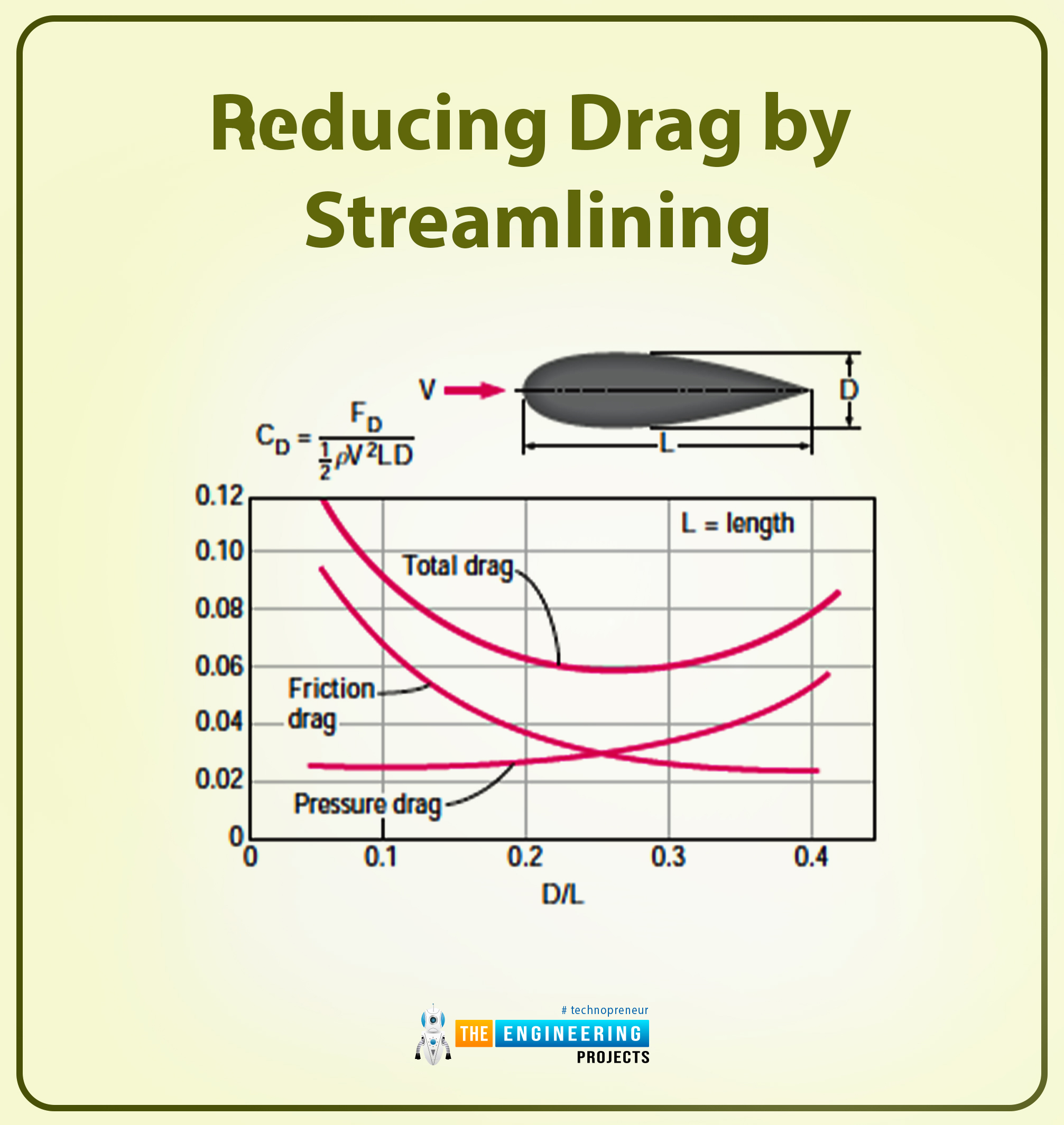
As you can see from the diagram, the value of total drag at minimum is D/L=0.25.
The drag coefficient value will be five times in the case of a circular cylinder having the same thickness as the streamlined shape.
In the case of an elliptical cylinder shape, the value of the drag coefficient is less. The elliptical cylinder shape is considered the perfect example for defining the effect of streamlining on a drag coefficient.
Flow Separation
I will define flow separation extensively, so the following is the definition of it.
The fluid has high velocity when force flows over a curved body. Similarly, fluid can climb uphill on a curved surface without distraction.
At high velocities, the fluid stream detaches itself from the body’s surface, known as flow separation.
A flow can be separated from a surface when fully submerged in an immersed gas or liquid.
Parallel Flow over Flat Surface
There are many essential terminologies for this topic, and the following are some important key points, equations, and definitions for the parallel flow over the flat surface. So let us start.
The following diagram shows a flat plate on which a fluid has flowed.
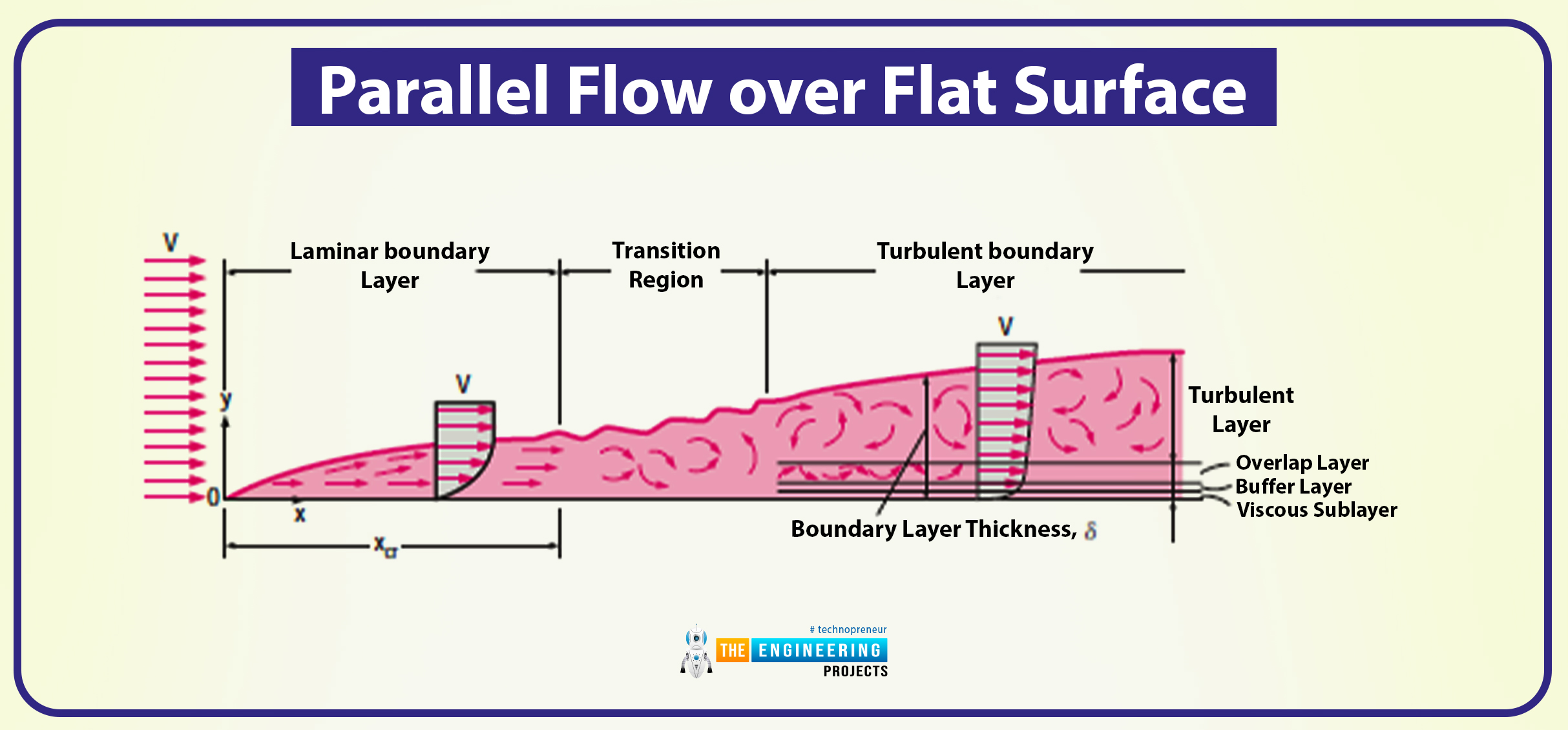
Taking this diagram as a reference, I will explain the whole topic through this.
Here, in this flat plate, the x-axis is measured along the plate surface (starting from the leading edge of the plate in the direction the fluid is flowing), whereas the y-coordinate is measured from the surface in the normal direction.
The surface’s velocity is equal to the velocity of the fluid that travels along the x-coordinate.
As you can see through the diagram, for our convenience, we have assumed that the fluid is in adjacent layers and they are piled onto one another
By doing so, the velocity of the first layer of fluid adjacent to the plate becomes zero, and this is due to the no-slip condition.
The first layer impacts the other layers by slowing the motion of particles of other different. And the process goes on as the layer slows down the next layer’s molecules.
The presence of the layer is then felt up to some normal distance (), from the plate, beyond which the free-stream velocity remains unchanged.
There are some critical regions and layers present on this layer, and they are defined as follows:
Velocity Boundary Layer
It is the region of the flow that is above the plate bounded by normal distance () in which the effect of the viscous shearing force caused by fluid viscosity is felt.
Irrotational Flow Region
It is the region where the frictional effect is negligible, and the velocity is constant.
The thickness of the boundary layer (δ) is the distance y from the surface at which u=0.99V.
There is a hypothetical line that is present on the layer (u=0.99V) that divides the flow into two regions, and they are named as follows:
Boundary Layer Region
Irrotational Flow Region
In this flat plate parallel to the flow condition, the pressure drag is zero, and the drag coefficient equals the friction drag coefficient. Mathematically we can present it as follows:
CD=CD,friction=Cf
Here Cf is the drag friction coefficient.
The equation for calculating the friction force on the plate is as follows:
FD=Ff=12CfAρV2
Here the A is the surface area of the plate.
From the diagram, you have observed that the velocity profile is in laminar and turbulent flows.
Also, the turbulent is much fuller than the laminar one. As it has four regions, and they are named as follows:
Viscous Sublayer
Buffer Layer
Overlap Layer
Turbulent Layer
The transition of laminar to turbulent flow is dependent on the geometry of the surface, roughness, upstream velocity, surface temperature, and many things.
The Reynold’s number at a distance x from the leading edge of a flat plate is as follows:
Rex=ρVx=Vxv
In the case of a flat smooth plate, the transition from a laminar to a turbulent flow starts at Reynold’s number RE≅1×10⁵. The flow does not become turbulent until the value of Reynold’s number reaches RE≅3×10⁶
Friction Coefficient
The following are some key points related to the friction coefficients:
In the case of laminar flow, we can calculate the value of friction coefficients by using the law of conservation of mass and momentum.
In the case of turbulent flow, it should be calculated experimentally and should be expressed in the empirical correlation.
The drag force for the whole surface can be calculated by using the average friction coefficient value.
In some cases, if we want drag force for a specific location, then in this condition, we must know the local value of the friction coefficient.
If we have the value of local values, then it becomes easy for us to calculate the average friction coefficient values:
Cf=1L0LCf,xdx
Flow over Cylinders and Spheres
It is one of the important related to lift and drag. So following are the important key points related to the flow over the cylinder and spheres:
In our daily life, if we look around, there are multiple examples of it. In tubes (shell and tube heat exchanger) involves the internal and external flow over the tubes.
In sports, cricket, soccer, and tennis balls are the best examples of this topic.
For calculating the circular cylinder or sphere, the external diameter is taken as D.
In Reynold’s number, the formula is as follows:
Re=VDv
Here the V stands for the uniform velocity of the fluid as it approaches the cylinder and sphere.
Here, the value of the critical Reynold’s number is Recr≅2×10⁵.
The change in total drag coefficient value is observed for the flow of cylinders and spheres.
It is not wrong to say that the drag force is due to the friction drag at the low value of Reynold’s number (Re< 10) and in the case of pressure drag at a higher value of Reynold’s number (Re>5000).
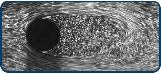
The following diagram shows the separation of the laminar boundary layer with the turbulent over a cylinder.
Effect of Surface Roughness
In the previous topic, I discussed this thing that the impact of having a surface makes a huge difference. So while discussing the cylinders and the spheres, it becomes important to discuss them in detail.
The following are some essential key points related to the topic:
The increase in surface roughness increases the drag coefficient in the case of turbulent flow.
For the streamlined case, it is also the same. But for the spheres and the cylinders, the increase in the roughness of the surface decreases the coefficient of drag. This means they have an indirect relationship.
The following diagram shows the indirect relation for cylinders and spheres.
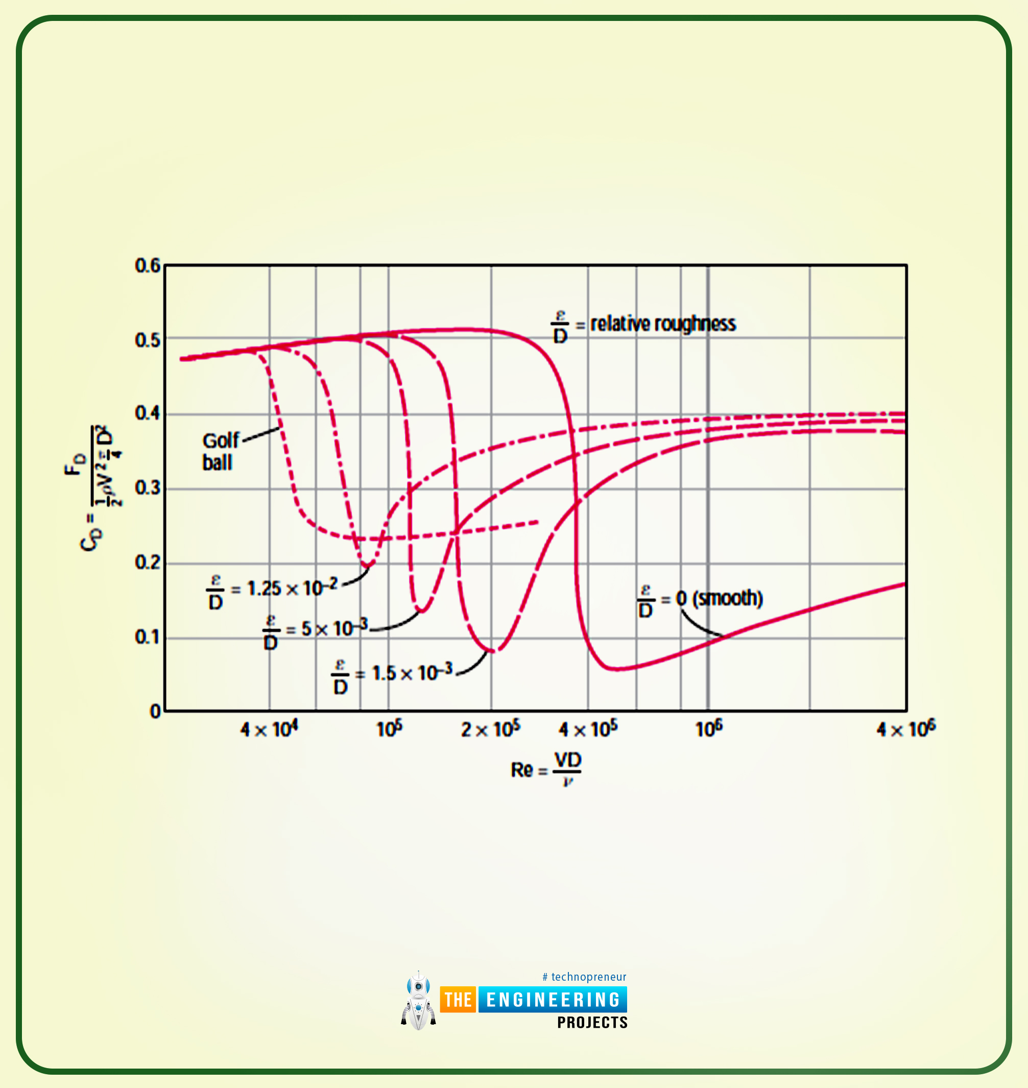
The indirect relation is done by tripping the boundary layer into turbulence at the lower value of Reynold’s number. The result is that the fluid is close in behind the body, reducing the pressure drag force.
The value of Reynold’s number is Re≅2×10⁵, and the value of the drag coefficient is CD≅0.1 in the case of a rough surface along with D=0.0015. In the case of a smooth surface, the values changes, and they become CD≅0.5.
The value of Reynold’s number for the rough sphere is Re≅106, and the drag coefficient value is CD≅0.4.
So the value of the drag coefficient for a smooth sphere is CD≅0.1.
The rougher the sphere will become, the more drag will also increase.
In order to exemplify the values, let us take an example of a golf ball. The velocity value ranges from 15 to 150m/s for the golf ball, and the value of Reynold’s number is 4×10⁵,.
Lift
At the start of the article, I have already discussed what lift is. Here in this topic, I will explain extensively about the lift and the mathematical equation.
In order to explain the topic in a symmetric manner, I will explain it in key points, and these are as follows:
As you know that lift is the component of the net force, and this net force is because of the viscous and pressure force.
The coefficient of the lift is explained as follows:
CL=FL12V2A
The A here presents the planform area, and this area is viewed by someone that is looking at it from above in a direction normal to the body.
The V is the upstream velocity.
We will consider the airfoil with a width b and chord length c and the planform area as A=bc, respectively.
The following is the diagram that shows the airfoil structure.
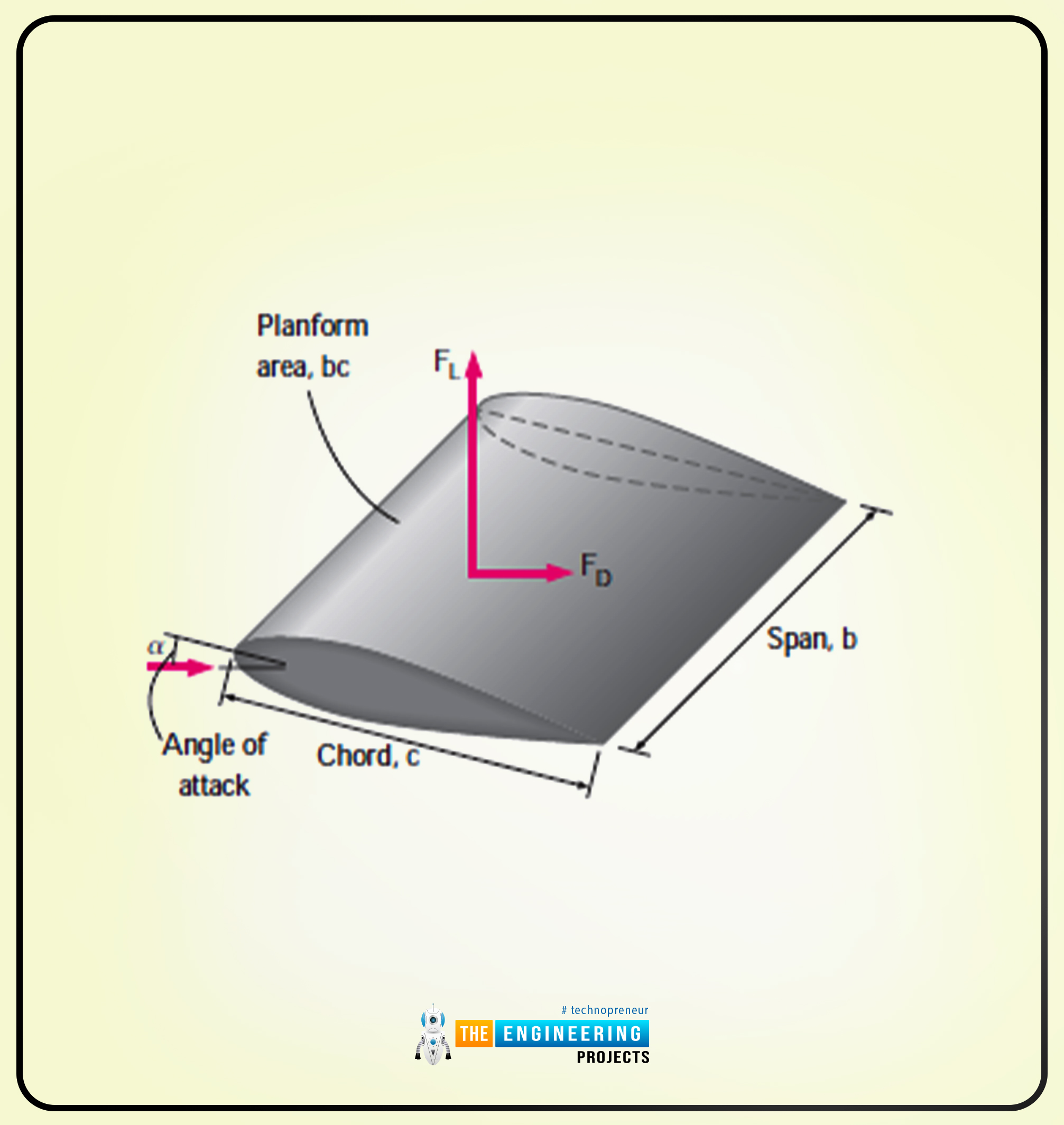
Here, there is a term called wingspan or span. It is the distance between the two ends of the foil.
In the case of aircraft, the wingspan is the total distance between the tips of two wings.
Another important term is wing loading. It is the average lift per unit planform area FLA.
The airplanes are all based on the lift.
The purpose of discussing the lift in detail is to know how airfoils are designed and how they generate lift by keeping the value of drag minimum.
The streamlined bodies, such as airfoils that intends to generate the lift, have a negligible lift, and the wall shear is parallel to the surface.
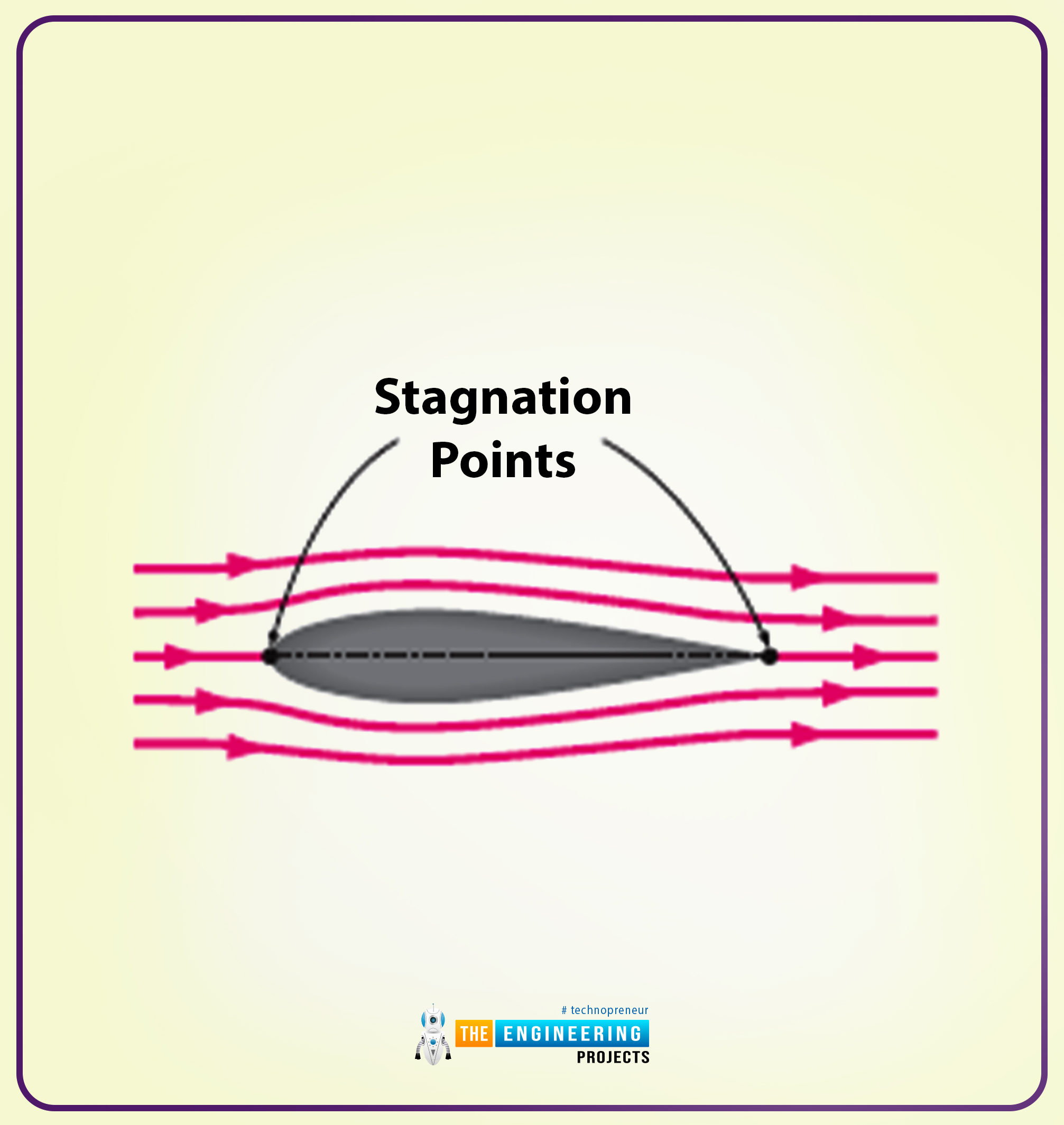
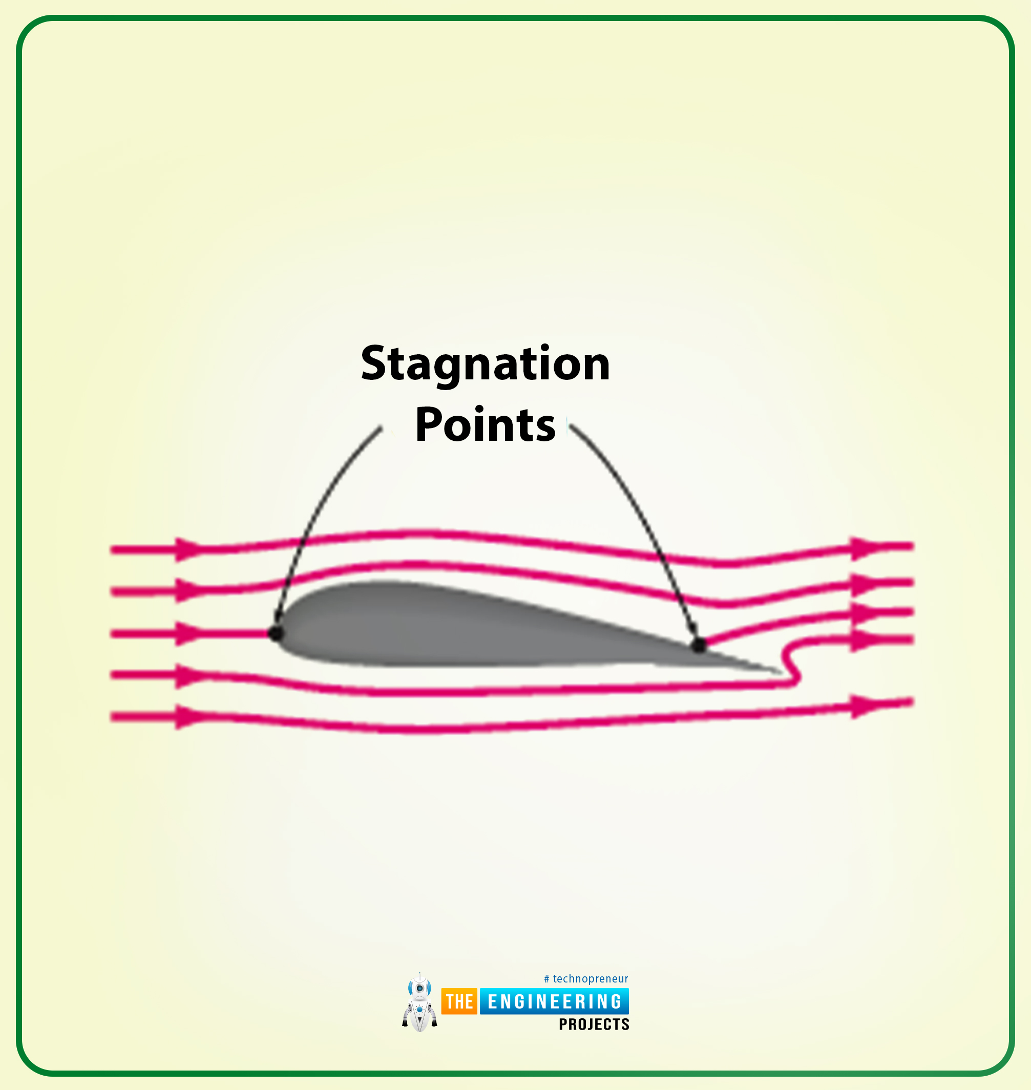
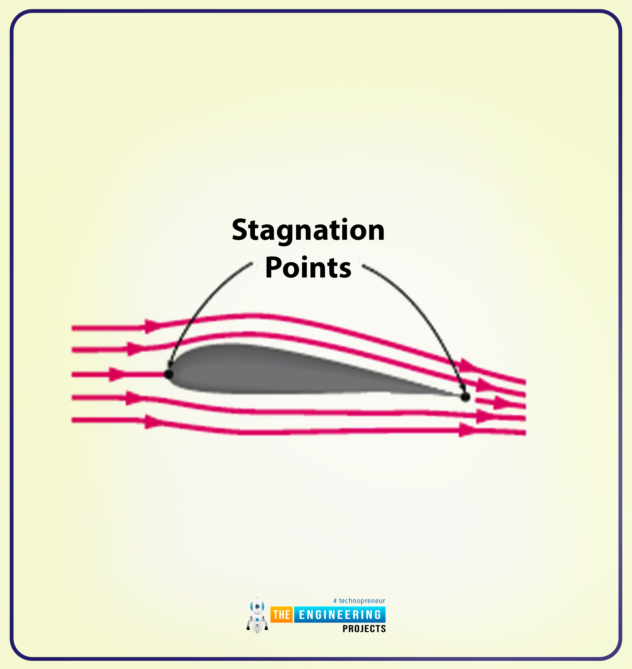
I will show you the pictorial representation of the irrotational and actual flow past the non-symmetrical two-dimensional airfoils.
The following diagram shows the irrotational flow past a symmetrical airfoil (here the lift is zero).
The following diagram shows irrotational flow past a non-symmetrical airfoil (having zero lift).
The following diagram shows the actual flow past a non-symmetrical airfoil, and here the lift is positive.
Conclusion
Hope you enjoy reading the article. I have tried my best to explain you every point in easy words. Thank you for reading.


 Fluid Mechanics
 syedzainnasir
 0 Comments


 2.3k
2.3k
 953
953
 921
921
 2.1K
2.1K

