Hello friends, I hope you are doing well. In today's tutorial, I am going to share our BME280 Sensor Library for Proteus V1.0. This library lets us simulate temperature, relative humidity and atmospheric pressure in one circuit. We will connect the sensor to an Arduino Uno, display its readings on a Virtual Terminal and change the environmental conditions while the simulation is running.
If you have followed our Flex Sensor Library for Proteus or Vibration Sensor Library for Proteus tutorials, the installation process will feel familiar. We will download the package, copy its library files, find the component and then test a complete circuit. This time, we also need to install a DLL that provides the sensor's simulation behavior.
The download includes the BME280 model, the TEP Arduino UNO V3 library, a wired Proteus project, the Arduino sketch and a compiled HEX file. You can run the supplied example first and study the code afterward. We will work through both routes, so you can understand the readings instead of simply copying a circuit.
What Is the BME280 Sensor?
The BME280 is an environmental sensor from Bosch Sensortec. It combines temperature, humidity and pressure sensing, making it useful when a project needs several environmental readings without using three separate devices. In this tutorial, our Arduino reads those values through an I2C connection.
Temperature tells us the sensor temperature in degrees Celsius. Relative humidity expresses the water vapor present relative to saturation at the same temperature. Pressure describes the atmospheric pressure at the sensor. These quantities have different units, so we will label every value in the terminal output.
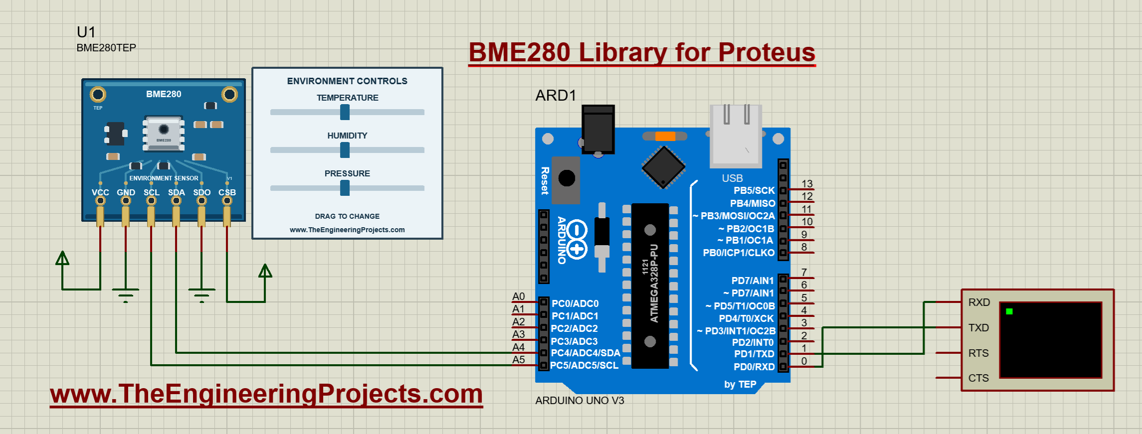
Our Proteus component is named BME280TEP. Beside its breakout-board artwork, you will see three sliders. Each slider controls one simulated input. Moving the humidity slider changes humidity independently of the temperature and pressure sliders. This makes it easy to test a program under a chosen condition and then reproduce the same test.
| Quantity | Slider range | Initial value | Terminal unit |
|---|---|---|---|
| Temperature | -40 to 85 degrees Celsius | 25.0 degrees Celsius | C |
| Relative humidity | 0 to 100 percent | 50.0 percent | % |
| Pressure | 300 to 1100 hPa | 1013.25 hPa | hPa |
These sliders represent simulated conditions. They do not read your room temperature or the weather outside. The model is useful for checking communication, calculations and program decisions before you connect a physical sensor.
Download the BME280 Sensor Library for Proteus
First of all, download the complete library package using the button below. Extract the ZIP into a normal folder before opening the project. Running files directly from a compressed-folder preview can prevent Proteus from finding the firmware or model files beside the project.
Download BME280 Sensor Library for Proteus V1.0Inside the extracted BME280-TEP-v1 folder, you will find the following items:
| Folder or file | Contents | Purpose |
|---|---|---|
| Proteus Library Files | TEPBME280.LIB, TEPBME280.IDX, ArduinoV3TEP.LIB and ArduinoV3TEP.IDX | Adds the sensor and demonstration Arduino board to the component picker. |
| Proteus Model Files | TEPBME280.DLL | Provides the sensor's interactive I2C simulation model. |
| Proteus Simulation | BME280-ArduinoUnoV3.pdsprj, BME280_Demo.hex and a copy of the DLL | Contains the wired demonstration and its linked firmware. |
| Arduino Code | Sketch, required libraries, AVR core archive and rebuild script | Lets you inspect, modify and rebuild the firmware. |
| Documentation | Model notes and third-party notices | Describes supported behavior and bundled dependencies. |
| README.txt and SHA256SUMS.txt | Quick-start instructions and file checksums | Provides setup guidance and a way to check the extracted package. |
The demonstration was tested with Proteus 8.5 SP0, the TEP Arduino UNO V3 and an ATmega328P running at 16 MHz. Your Proteus installation needs AVR simulation support. Proteus 7 and other releases have not been verified for this package; the supplied project uses the Proteus 8 PDS project format.
How to Install the BME280 Library in Proteus
Let us install the files before opening the example. There are two destinations: the library directory and the model directory. The LIB and IDX files make the device available for placement; the DLL makes the sensor work when simulation begins.
- Close Proteus. Save any open work, then exit the program so it can reload the newly installed library on its next start.
- Open the extracted Proteus Library Files folder. Select
TEPBME280.LIB,TEPBME280.IDX,ArduinoV3TEP.LIBandArduinoV3TEP.IDX. - Copy those four files into your configured Proteus LIBRARY directory. Use the data directory belonging to the Proteus installation you actually run. A common Proteus 8 location is
C:\ProgramData\Labcenter Electronics\Proteus 8 Professional\DATA\LIBRARY, but installations can use a different location. - Open Proteus Model Files. Copy
TEPBME280.DLLinto the corresponding ProteusMODELSdirectory. In installations using the example data path above, this is commonlyC:\ProgramData\Labcenter Electronics\Proteus 8 Professional\DATA\MODELS. - Restart Proteus. Open the schematic editor and use the Pick Devices control, normally marked P.
- Search for BME280TEP. Select the sensor and place it on the schematic. You should see the blue sensor board and its three environmental controls.
If Windows hides ProgramData, enable hidden items in File Explorer or enter the directory directly in the address bar. Check the library and model paths configured for your installation before copying files into several different directories. Multiple old copies can make it difficult to tell which model Proteus has loaded.
The simulation folder already contains another copy of the sensor DLL. Keep it beside the supplied project. Installing the DLL in MODELS is also useful when you place BME280TEP in a different project. You do not need to select a sensor HEX file in the BME280 properties: this sensor uses a DLL, while BME280_Demo.hex runs on the Arduino.
If you already have the TEP Arduino UNO V3 library installed, keep a backup of your existing files before replacing them. The paired LIB and IDX files should come from the same library release. Our earlier Arduino Library for Proteus tutorial explains the general component-library workflow.
BME280 Pinout and Arduino Uno Connections
Now that the component is available, let us examine its six pins. SDA carries I2C data, and SCL carries the clock. The Arduino Uno uses A4 for SDA and A5 for SCL. Although those pins are also labeled as analog inputs, we use them as digital communication pins here; the sketch does not call analogRead().
| Sensor pin | Connect to | Reason |
|---|---|---|
| VCC | Positive supply rail in the simulation | Powers the model. |
| GND | Common ground | Provides the shared reference. |
| SCL | Arduino A5 | Connects the I2C clock. |
| SDA | Arduino A4 | Connects bidirectional I2C data. |
| SDO | GND | Selects the seven-bit address 0x76. |
| CSB | VCC | Selects I2C operation. |
Connect Arduino D1/TX to the Virtual Terminal RXD input. That connection carries the printed measurements. The supplied circuit also connects terminal TXD to Arduino D0/RX, although this sketch only prints readings and does not need incoming commands. Set the terminal to 9600 baud, eight data bits, no parity and one stop bit.
Start wires at the exposed ends of the component pins below the artwork. A wire that only touches a painted pad can look connected without making an electrical connection. When checking a circuit, follow each actual net rather than relying on the appearance of the board graphic.
For physical hardware: do not infer voltage compatibility from the simulation drawing. Bosch specifies VDD of 1.71 to 3.6 V and VDDIO of 1.2 to 3.6 V for the bare device. A particular breakout may add a regulator and level shifting; check its documentation before connecting a 5 V Uno. The demo enables Wire pull-ups for simulation, whereas a physical I2C bus needs pull-ups and voltage levels suitable for the actual devices. See the Bosch BME280 specifications.
Run the Supplied Proteus Simulation
I recommend running the supplied circuit before changing its wiring or program. This gives you a known starting point. If your modified circuit later stops working, you can compare it with the original instead of troubleshooting the library installation and your changes at the same time.
- Open
Proteus Simulation/BME280-ArduinoUnoV3.pdsprjfrom the extracted package. - Keep
BME280_Demo.hexandTEPBME280.DLLin that simulation folder. - Double-click the Arduino and check its Program File property. It should point to the supplied BME280_Demo.hex.
- Confirm the Arduino clock is 16 MHz and the terminal baud rate is 9600.
- Press Run. Open the Virtual Terminal window if it is not already visible.
The terminal first prints the demonstration heading and a message about the sliders. It then prints temperature, humidity and pressure repeatedly. At the initial settings, the supplied firmware reports approximately 25.0 C, 50.0% humidity and 1013.2 hPa.
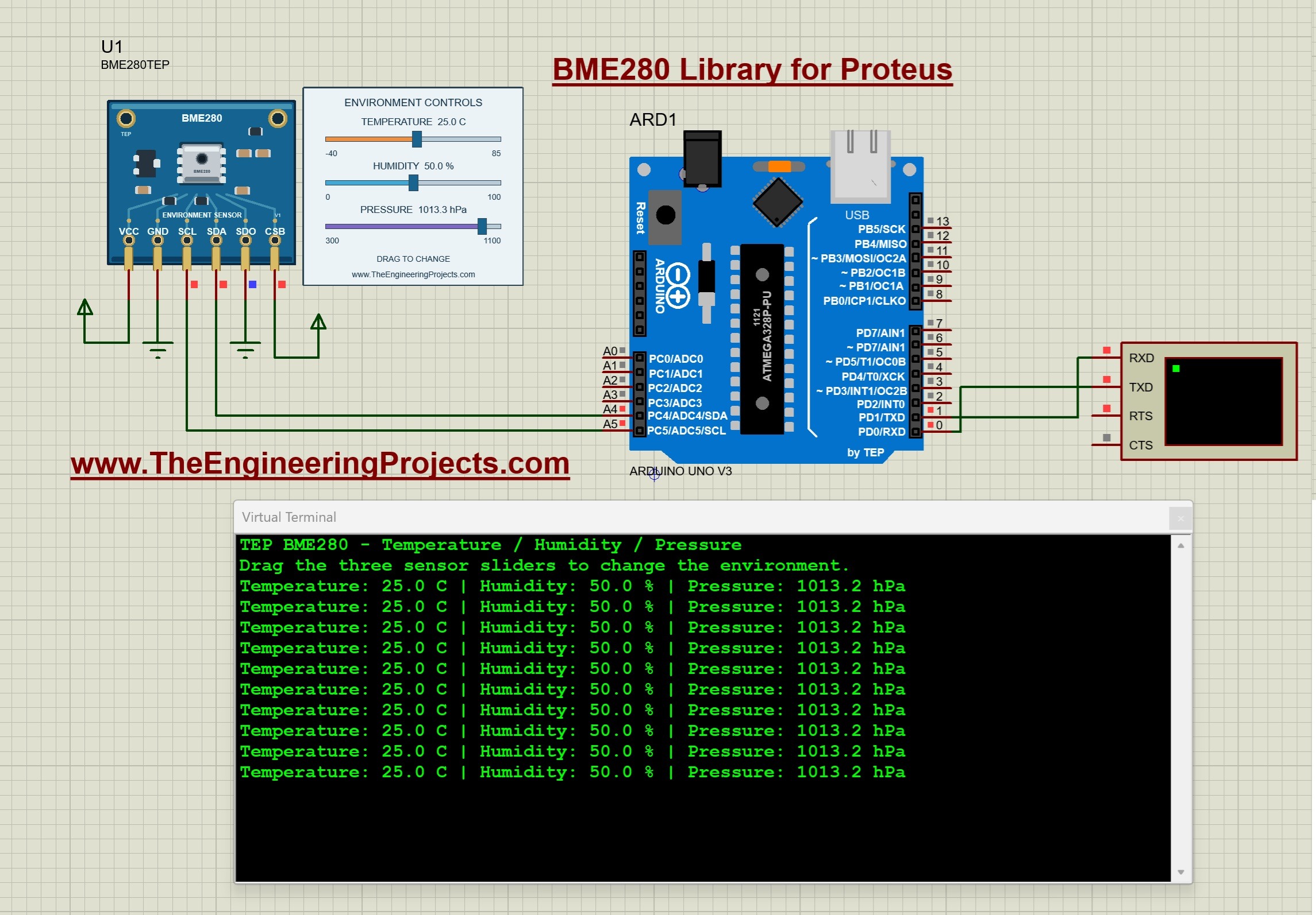
You may notice 1013.3 hPa on the control panel while the terminal shows 1013.2 hPa. The initial pressure input is 1013.25 hPa. The model converts that input into raw sensor data, the driver compensates it, and both displays format their results to one decimal place. A difference of 0.1 hPa at this rounding boundary is expected; it does not mean you connected the sensor incorrectly.
Change the Environmental Conditions
While the simulation is running, drag the temperature slider and watch the next terminal lines. Then change humidity, followed by pressure. Make one change at a time for your first test. This helps you confirm which value each control affects and makes unexpected behavior easier to identify.
The following screenshot shows the readings after several slider changes. The final displayed combination is about 75.8 C, 80.5% humidity and 705.3 hPa. Earlier terminal lines remain visible because the terminal keeps a history of previous readings; they are not additional sensors.
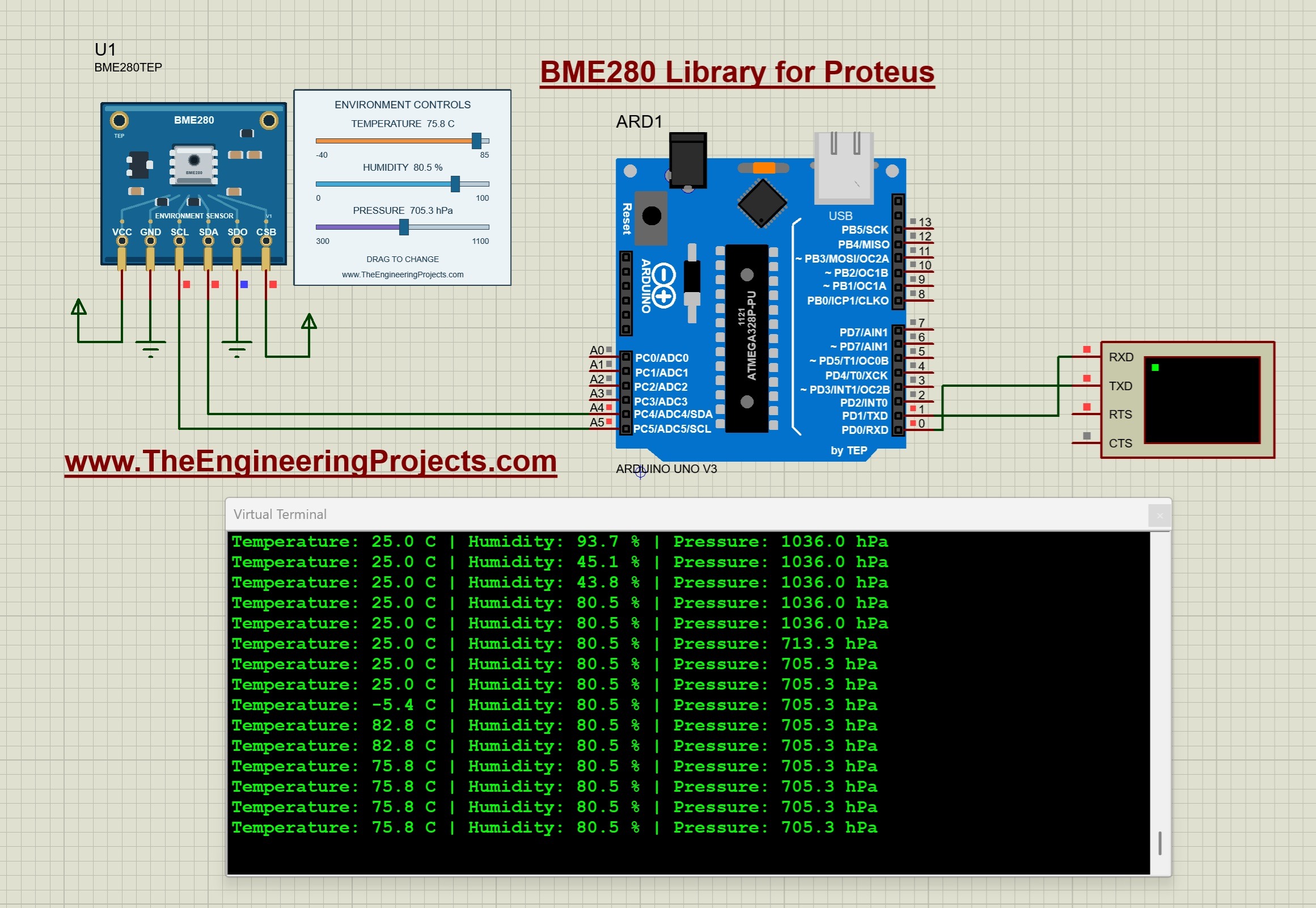
Stopping and restarting the simulation restores the initial values stored in the sensor's component properties. If you want a repeatable starting condition, edit those properties before running. The NAME, VERSION and Designed by fields identify the library and are read-only.
Arduino Code for the BME280 Proteus Simulation
The following sketch performs the same operations as the example included in the ZIP. It starts serial communication, initializes I2C, checks the sensor address and prints the three compensated readings. The precompiled HEX is already provided, so compiling this code is optional until you want to change the program.
#include <Arduino.h>
#include <Wire.h>
#include <Adafruit_BME280.h>

Adafruit_BME280 sensor;
bool ready = false;

void setup() {
  Serial.begin(9600);
  Wire.begin();
  Wire.setClock(100000);
  Wire.setWireTimeout(25000, true);
  delay(10);

  Serial.println(F("TEP BME280 - Temperature / Humidity / Pressure"));
  ready = sensor.begin(0x76, &Wire);
  if (!ready) {
    Serial.println(F("Sensor not found. Check power, SDA, SCL, SDO and CSB."));
    return;
  }

  sensor.setSampling(Adafruit_BME280::MODE_NORMAL,
    Adafruit_BME280::SAMPLING_X1,
    Adafruit_BME280::SAMPLING_X1,
    Adafruit_BME280::SAMPLING_X1,
    Adafruit_BME280::FILTER_OFF,
    Adafruit_BME280::STANDBY_MS_125);

  Serial.println(F("Drag the three sensor sliders to change the environment."));
  delay(200);
}

void loop() {
  if (ready) {
    Serial.print(F("Temperature: "));
    Serial.print(sensor.readTemperature(), 1);
    Serial.print(F(" C | Humidity: "));
    Serial.print(sensor.readHumidity(), 1);
    Serial.print(F(" % | Pressure: "));
    Serial.print(sensor.readPressure() / 100.0F, 1);
    Serial.println(F(" hPa"));
  }
  delay(500);
}
Understand the Important Settings
sensor.begin(0x76, &Wire) matches the SDO-to-ground connection in our circuit. Connecting SDO high selects 0x77, so the sketch must use that address instead. Changing only the address in the code will not change the address selected by the circuit.
Wire.setClock(100000) requests a 100 kHz I2C clock. The timeout setting gives Wire a way to recover from a transaction that remains stuck. The supplied Arduino AVR core supports this API; a different board package may expose different timeout functions.
The sampling call selects normal mode, x1 oversampling for temperature, pressure and humidity, filtering off, and a 125 ms standby interval. Turning filtering off makes this first slider demonstration easier to follow. The 500 ms delay controls how often the program prints, so terminal updates occur roughly twice per second with some additional execution and communication time.
Compile Your Own HEX File
- Open
Arduino Code/BME280_Demo/BME280_Demo.inoin Arduino IDE. - Select Arduino Uno and the Arduino AVR Boards 1.8.6 core used by the supplied example.
- Copy the three folders from
Arduino Code/librariesinto your sketchbook's libraries folder: Adafruit_BME280, Adafruit_BusIO and Adafruit_Sensor. - Compile the sketch and use the IDE's Export Compiled Binary command.
- Load the application HEX into the Arduino Program File property in Proteus. For this direct firmware simulation, choose the application HEX rather than the version named with_bootloader.
- Restart the simulation after selecting the rebuilt file.
The package includes Adafruit BME280 2.3.0 and the dependencies used by the demonstration. Using the bundled copies gives you a reproducible starting point. A separate PowerShell build script is also included for readers with an AVR GCC toolchain; its required compiler and Arduino-core directory arguments are explained in README.txt.
How the BME280 Simulation Works
Let us look beyond the sliders. The Arduino does not read the slider position directly. It communicates with the sensor model over I2C, using the same kind of register operations that a sensor driver expects. The model exposes identification, calibration, configuration, status and measurement registers.
When the driver initializes the device, it checks the chip identity and loads calibration coefficients. During operation, it reads raw temperature, pressure and humidity data and converts those values into engineering units. Our model supplies synthetic calibration data and raw measurements chosen to represent the selected environmental inputs.
This is why a functional simulation can catch mistakes that a fixed text display would miss. Wrong addressing, swapped SDA and SCL connections, a missing model or incorrect initialization can prevent the sketch from obtaining valid readings. Seeing the expected terminal output confirms that several parts of the demonstration are working together.
V1.0 supports both I2C addresses, register reads and writes, repeated starts, reset behavior, forced and normal measurement modes, conversion timing and temperature/pressure IIR filtering. It also keeps the measurement registers consistent during a read transaction. These features help firmware interact with the model through a normal sensor library.
The model remains a functional simulation with deterministic inputs. It does not reproduce electrical noise, manufacturing tolerances, power consumption or the physics of an atmosphere. Increasing oversampling changes modeled conversion timing; it does not add realistic random noise. The physical BME280 also supports SPI, but SPI is outside the scope of this V1.0 model.
Useful Calculations for the Readings
Convert Pressure from Pascals to hPa
The driver returns pressure in pascals, while our display uses hectopascals. One hectopascal equals 100 pascals, so we divide by 100:
Pressure in hPa = pressure in Pa / 100
For example, 101325 Pa becomes 1013.25 hPa. The expression sensor.readPressure() / 100.0F performs this conversion in the sketch. If your display shows a value close to 101325 but labels it hPa, check the unit conversion before investigating the sensor.
Convert Celsius to Fahrenheit
If your project needs Fahrenheit, use the Celsius reading in this equation:
Temperature in Fahrenheit = temperature in Celsius × 9 / 5 + 32
At the default 25.0 C setting, the result is 77.0 F. Store the Celsius measurement in a variable, calculate Fahrenheit from it and print both labels correctly. Reusing a single reading also makes the relationship between the two displayed values clear.
Compare Measurement Timing with Display Timing
For all three channels enabled at x1 oversampling, the Bosch maximum conversion-time formula gives 1.25 + 2.3 + (2.3 + 0.575) + (2.3 + 0.575) = 9.3 ms. Including the selected 125 ms standby interval gives a nominal cycle estimate of 134.3 ms, or about 7.45 cycles per second. This uses the maximum-time expression as an estimate, not a measured performance result. The formula is in Appendix B of the Bosch BME280 datasheet.
Our sketch prints more slowly because its loop waits 500 ms between lines. A fresh measurement can therefore exist before the next terminal line appears. If you enable filtering, allow additional settling time when testing a large temperature or pressure step.
Try These Simulation Exercises
Once the basic example works, use the controls to test a small application. Choose one change, write down the expected result and then compare that expectation with the terminal output.
- Temperature alarm: print a warning above 35 C. To avoid repeatedly switching near the threshold, clear the warning only below 33 C. Test below, between and above the two thresholds.
- Humidity monitor: classify readings below 30%, between 30% and 70%, and above 70%. Decide how exactly 30% and 70% should be handled, then test those boundary values.
- Pressure display: show the same pressure in Pa and hPa. Move the pressure slider and check that the numerical ratio remains 100.
- Address-selection test: change SDO to high and update the sketch to 0x77. Test the mismatched configuration first to observe the initialization error, then correct it.
- Filtered response: enable an IIR filter and apply a temperature or pressure step. Compare how quickly the reading settles with the unfiltered example.
Keep your modified circuit in a separate project folder with its matching HEX file. A descriptive folder name and a short note about your sampling settings make comparisons much easier when you return to the experiment later.
Common Problems and Their Solutions
| Problem | What to check |
|---|---|
| BME280TEP is missing from Pick Devices. | Confirm both sensor LIB and IDX files are in the active library directory. Restart Proteus and search for the exact device name. |
| The sensor can be placed, but its model cannot load. | Check TEPBME280.DLL in MODELS and the copy beside the supplied project. Library installation and model installation are separate steps. |
| The terminal reports Sensor not found. | Check power, common ground, SDA/A4, SCL/A5, SDO/GND and CSB/VCC. Confirm the code uses 0x76. |
| The terminal window is blank. | Check Run, the Arduino Program File, the 16 MHz clock, D1/TX to RXD and the 9600 baud setting. |
| Serial characters are unreadable. | Match the terminal baud rate to Serial.begin(9600), then check the Arduino clock and serial format. |
| The program behaves like an older version. | Confirm you rebuilt the sketch and selected that exact HEX file. Editing the INO alone does not update firmware already loaded in Proteus. |
| Slider changes are not immediately visible. | Allow time for a conversion and the next printed line. Check whether your modified firmware enables filtering. |
| The component still has old artwork. | Restart Proteus and update the placed component from the installed library. Recheck the actual wire endpoints. |
If a problem remains, return to the unmodified demonstration and change one thing at a time. When asking for help, include your Proteus version, the displayed error, the sensor address and a screenshot showing the wiring. Those details are more useful than reporting only that the library does not work.
Practical Review of Library V1.0
The main advantage of this library is that we can vary three inputs while real firmware communicates with a sensor model. The included project and HEX reduce the initial setup work, and the source code lets us move from observing readings to testing our own decisions. For teaching, the separate sliders make cause and effect easy to follow.
Its limits matter when choosing a project. Use it to examine I2C communication, unit conversion, display logic and thresholds. Evaluate electrical margins, physical accuracy and environmental behavior with real hardware. Keep SPI projects separate, since this release implements I2C only.
Frequently Asked Questions
Does the Download Include the Arduino Library?
Yes. The Proteus Library Files folder contains the TEP Arduino UNO V3 LIB and IDX pair used by the demonstration. The Arduino Code folder also contains the software libraries needed to rebuild the BME280 sketch. These are different kinds of libraries and belong in different locations.
Should I Put BME280_Demo.hex into the Sensor Properties?
No. Select that HEX file in the Arduino's Program File property. The BME280TEP sensor uses TEPBME280.DLL as its simulation model. This differs from some older TEP sensor libraries that used a HEX file inside the sensor component.
Can I Use Another Microcontroller?
The model communicates over I2C, so another simulated controller can potentially use it if its firmware implements the required transactions. However, the supplied circuit and firmware target the Arduino Uno's ATmega328P. A different controller requires its own compatible driver, wiring and compiled program; the Uno HEX cannot simply be loaded into it.
Why Does the Stopped Sensor Show No Live Numbers?
The stopped view displays the control labels without live measurements. Start the simulation to activate the environmental controls and terminal output. Stopping and restarting resets the inputs to the component-property values, so slider positions from an earlier run should not be treated as permanent settings.
Can I Simulate Two BME280 Sensors on One I2C Bus?
The model supports 0x76 and 0x77. Two instances can therefore be configured with different SDO states, provided your firmware initializes and reads both addresses. This requires modifying the single-sensor example. Keep CSB high on both devices and avoid assigning both instances the same address.
Will This Package Work in Every Proteus Version?
The verified configuration is Proteus 8.5 SP0 with AVR simulation support. Compatibility with every other release is not established. If you use a different version, begin with the unchanged example and check the project format and model-loading behavior before adapting a larger circuit.
Can the Pressure Reading Be Used to Calculate Altitude?
You can extend the sketch with the Adafruit library's altitude calculation, but it needs a sea-level reference pressure and assumes an atmospheric relationship. The sliders themselves do not simulate altitude or weather. Treat any resulting altitude as a calculation from your chosen inputs, rather than an independently measured quantity.
That completes our BME280 Sensor Library for Proteus tutorial. Start with the supplied circuit, confirm the three readings, then change one slider and one part of your program at a time. Share your observations and project questions in the comments so we can discuss the results.