Hello friends, I hope you all are doing great. Today, I am going to share the new MPU6050 Sensor Library for Proteus V1.1. The MPU6050 is the popular 6-axis motion sensor: a 3-axis accelerometer, a 3-axis gyroscope and a temperature sensor in one small chip, best known on the blue GY-521 board. With this MPU6050 Sensor Library for Proteus, you tilt, turn and shake the sensor with presets, sliders or a click on its artificial horizon, and your Arduino reads it over I2C with the same Adafruit MPU6050 library you use on real hardware.
MPU6050 Sensor Library for Proteus
Latest version: V1.1 (September 2026, this tutorial)
Other IMU sensors: MPU9250 · ADXL345 · GY-271 Compass
Helping Tools
- Serial Monitor Advance: a serial terminal window for the UART of your board
- Serial Monitor Expert: the serial monitor with extra debugging tools
- LCD Library for Proteus V3.0: 16x2, 20x4 and I2C LCDs to show your readings
Version 1.1 replaces the first version of this post. You now get two devices: MPU6050 Simple, with a control panel on the schematic, and MPU6050 Advance, with a pop-up window and four measured sensor test tools. The model now has the digital low-pass filter with its real delay, motion detection with the INT pin, and the data-ready and FIFO interrupts. The new MPU6050 Arduino Proteus demo runs on two Arduino UNOs with a tilt alarm LED, shown in the compact Simple interface of our TEP Serial Monitor. Have you read version 1.0? Then jump to "What's New" below.
NOTICE: This library is very special to our team. Our MPU6050 model has the chip's register map, the four ranges, the digital low-pass filter with its delay, the FIFO, the motion detector and the INT pin, and it speaks I2C to the unmodified Adafruit library. It took our team a lot of hard work, many test runs and many design changes. Your feedback is the fuel that keeps us going, so please tell us what you think in the comments below or in the MPU6050 Library board of our forum. And if our free libraries help you, you can buy us a coffee. So, let's get started with the MPU6050 Sensor Library for Proteus:
What is the MPU6050 Sensor?
The MPU-6050, made by InvenSense (today TDK InvenSense), is a 6-axis motion sensor. Its accelerometer measures the acceleration along X, Y and Z, gravity included, and its gyroscope measures how fast the sensor turns about the same three axes. A third sensor reports the temperature of the chip. Your Arduino reads all of it over I2C, the 2-wire bus with a clock line (SCL) and a data line (SDA). For more background, read our Introduction to MPU6050.
Acceleration and rotation are different things. A sensor lying still on a table reads 1 g on its Z axis, because it feels gravity, and 0 deg/s on the gyroscope, because it does not turn. A gyroscope reading of 90 deg/s is a rotation rate, not an angle of 90 degrees.
The MPU6050 at a Glance
| Feature | Value |
|---|---|
| Measures | Acceleration on X, Y, Z (gravity included), rotation rate about X, Y, Z, and the die temperature (our sliders: ±16 g, ±2000 deg/s, -40 to 85 C) |
| Interface | I2C, standard and fast mode, at 0x68 (AD0 LOW) or 0x69 (AD0 HIGH) |
| Chip ID | WHO_AM_I = 0x68 |
| Accelerometer ranges | ±2, ±4, ±8 or ±16 g |
| Gyroscope ranges | ±250, ±500, ±1000 or ±2000 deg/s |
| Digital low-pass filter | 260, 184, 94, 44, 21, 10 or 5 Hz, with a delay of 0 to 19 ms |
| Sample rate | 1 kHz with the filter on (8 kHz gyro with it off), divided by 1 + SMPLRT_DIV |
| Interrupts | Data ready, FIFO overflow and motion, on the INT pin |
| FIFO | 1024 bytes (accelerometer, temperature, gyro) |
| Supply | A 3.3 V chip; the GY-521 has a 3.3 V regulator (662K), so it takes 5 V or 3.3 V on VCC |
MPU6050 Terms You Will See in This Article
| Term | Meaning |
|---|---|
| g | 9.80665 m/s², the pull of gravity; lying flat, the sensor reads +1 g on Z |
| deg/s | A rotation rate in degrees per second, not an angle |
| Pitch, roll | The two tilt angles the demo computes from the accelerometer: nose up / down, and sideways |
| LSB (count) | One step of the signed 16-bit register value |
| DLPF | The digital low-pass filter: it smooths the data and delays it |
| SMPLRT_DIV | The sample-rate divider: 1 kHz / (1 + SMPLRT_DIV) with the filter on |
| High-pass filter (HPF) | Removes gravity and a steady tilt before the motion detector |
| MOT_THR, MOT_DUR | The motion threshold (2 mg per count in our model) and duration (1 ms per count) |
| INT pin, INT_STATUS | The interrupt output, and the register that says which event happened |
| FIFO | A 1024-byte buffer that stores samples for later reading |
| AD0 | The address pin: LOW = 0x68, HIGH = 0x69 |
How the MPU6050 Measures: Gravity, Ranges, Filter and Interrupts
Gravity and the Tilt Angles
The accelerometer always feels gravity. Lying flat, the MPU6050 reads 0, 0 and 1 g; upside down, Z reads -1 g; with all three at 0, the sensor is in free fall. Tilt it, and gravity spreads over the axes: rolled 45 degrees, Y and Z each read 0.71 g (cos 45° = 0.707). That is how a still sensor knows its tilt. The demo sketch computes it with atan2:
pitch = atan2(-AX, √(AY² + AZ²)), roll = atan2(AY, AZ)
This only works while the sensor holds still. During a shake, the extra acceleration bends the result, as the SHAKE preset will show.
The Gyroscope Measures a Rate
The gyroscope gives degrees per second. To get an angle, multiply by the time: 90 deg/s for 0.5 s is 45 degrees. A real gyroscope has a small bias and noise, so such a sum drifts; the simulation has neither, which makes it a clean place to check your maths and your signs.
Ranges and Resolution
Every value is a signed 16-bit number. The range your sketch chooses sets how many counts make one g or one deg/s:
| Accelerometer range | Counts per g | Gyroscope range | Counts per deg/s |
|---|---|---|---|
| ±2 g | 16384 | ±250 deg/s | 131 |
| ±4 g | 8192 | ±500 deg/s | 65.5 |
| ±8 g | 4096 | ±1000 deg/s | 32.8 |
| ±16 g | 2048 | ±2000 deg/s | 16.4 |
The demo uses the widest ranges, so 2048 counts are 1 g and 16.4 counts are 1 deg/s; the Adafruit library does the dividing for you. At the very end of the gyro slider, 2000 x 16.4 = 32800 does not fit into 16 bits (32767 at most), so the reading stops at about 1998.0 deg/s. That is the register limit, not a bus error.
The Digital Low-Pass Filter and Its Delay
The MPU6050 can smooth its data with a digital low-pass filter (DLPF), set in the CONFIG register. A narrower filter is smoother, but slower. Version 1.1 models the data sheet's delay as a first-order lag:
| DLPF_CFG | Bandwidth | Accelerometer delay | Gyroscope delay |
|---|---|---|---|
| 0 | 260 Hz | 0 ms | 0.98 ms |
| 1 | 184 Hz | 2.0 ms | 1.9 ms |
| 2 | 94 Hz | 3.0 ms | 2.8 ms |
| 3 | 44 Hz | 4.9 ms | 4.8 ms |
| 4 | 21 Hz | 8.5 ms | 8.3 ms |
| 5 | 10 Hz | 13.8 ms | 13.4 ms |
| 6 | 5 Hz | 19.0 ms | 18.6 ms |
The demo sets 21 Hz, so a change reaches the data registers about 8.5 ms later. Through the 5 Hz filter, a 1 g step reads 0.63 g after 19 ms. Version 1.0 stored the filter setting, but had no filter dynamics.
Sample Rate, Data Ready and the FIFO
With the filter on, the chip makes 1000 samples a second, divided by 1 + SMPLRT_DIV (the gyro runs at 8 kHz with the filter off). Every new sample sets the data-ready flag in INT_STATUS. The demo leaves SMPLRT_DIV at 0, so a new sample comes every 1 ms. The 1024-byte FIFO can collect samples for a sketch that reads them in bursts; the demo does not use it.
Motion Detection and the INT Pin
Motion detection was missing in v1.0. The chip runs the accelerometer data through a high-pass filter (reset, 5, 2.5, 1.25 or 0.63 Hz, or hold), so gravity and a steady tilt drop out and only changes remain. When a change is bigger than the threshold MOT_THR for longer than MOT_DUR (1 ms per count), the chip sets the motion bit in INT_STATUS. Our model counts MOT_THR as 2 mg per count; the register map does not state this scale, so it is a model value.
Every event (data ready, motion, FIFO overflow) can drive the INT pin: active high or low, push-pull or open drain, as a 50 us pulse or latched until your sketch reads INT_STATUS. So Adafruit's motion_detection example works with our model.
The I2C Address: AD0
The AD0 pin sets the address: LOW gives 0x68, HIGH gives 0x69, so two MPU6050s can share one bus. Change AD0 and the address in begin() together.
What's New in MPU6050 Sensor Library for Proteus V1.1
If you used version 1.0, here is what has changed:
- Two devices in
TEPMPU6050.LIB: MPU6050 Simple (MPU6050TEP, the v1.0 device) and MPU6050 Advance (MPU6050ADVTEP) with a pop-up window. - A redrawn, live board: the royal-blue GY-521 with an animated instrument window above it (artificial horizon, gyro and temperature bars), PWR / I2C / INT LEDs (a TEP addition) and the live I2C address.
- Six presets (FLAT, TILT 30, ROLL 45, UPSIDE DOWN, SHAKE, SPIN) and a horizon you click to tilt the sensor; the Simple panel closes with a red X.
- The DLPF delay of the data sheet (v1.0 had no filter dynamics).
- Motion detection with MOT_THR, MOT_DUR and the high-pass filter, and the INT pin: polarity, push-pull or open drain, latched or 50 us pulses.
- Data-ready and FIFO-overflow interrupts.
- An I2C log: every read and write decoded, and the SCL clock measured on the pin.
- Four measured test tools on the Advance.
- A two-UNO demo with the TEP Serial Monitor instead of the Virtual Terminal: a tilt line, a tilt alarm LED and eight commands; every v1.0 output line is kept.
- Lighter package: about 1.66 MB, without the C++ source code and the AVR core archive.
And your old designs keep working. A design with the v1.0 symbol runs with the new model and shows the old MPU6050 CONTROLS panel; here, the v1.0 demo with the v1.1 DLL:
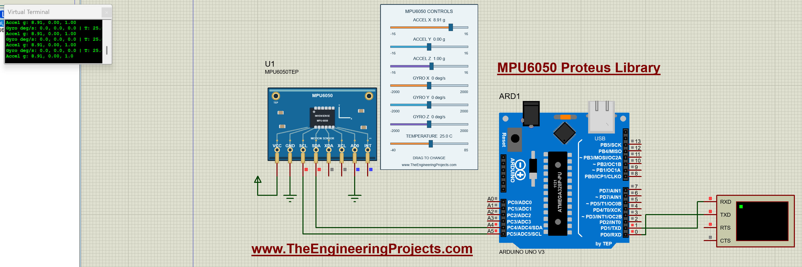
Re-pick the part from the library to get the v1.1 board and the red X.
MPU6050 Sensor Library for Proteus: Simple vs Advance
Both devices run the same model with the same properties; only the panel differs:
| Feature | Simple | Advance |
|---|---|---|
| Full MPU6050 model (0x68 / 0x69, ranges, DLPF delay, FIFO, motion detection, INT pin) | ✔ | ✔ |
| Blue GY-521 board: live horizon, gyro and temperature bars, PWR / I2C / INT LEDs | ✔ | ✔ |
| Control panel on the schematic (six presets, seven sliders, what the sketch read) | ✔ | ✘ |
| Pop-up window you can move, resize and minimise | ✘ | ✔ |
| Sensor page: a large live horizon, presets, click-sliders with - / + | ✘ | ✔ |
| I2C check, Timing, Step response and Orientation | ✘ | ✔ |
| TEP Dark / Light theme, text size, Help page with Copy diagnostics | ✘ | ✔ |
| Same device name as v1.0 (old designs keep working) | ✔ | ✘ |
Choose Simple to keep the controls beside your circuit, and Advance when your sheet is full or you want hard numbers about your sketch. The demo has one of each.
Download MPU6050 Sensor Library for Proteus
Click the button below to download MPU6050-Sensor-Library-for-Proteus-v1.1.zip (about 1.66 MB, without the C++ source code):
MPU6050 Sensor Library for Proteus V1.1- README.txt: a detailed guide to the files, the wiring, the model, the test tools and real hardware.
- Proteus Library Files:
TEPMPU6050.LIB(both devices),TEPSERIALMON.LIBand our Arduino UNO libraryArduinoV3TEP.LIB/ArduinoV3TEP.IDX. - Proteus Model Files:
TEPMPU6050.DLLandTEPSERIALMON.DLL. - Proteus Simulation:
MPU6050-ArduinoUnoV3.pdsprj,MPU6050_Demo.hex(both UNOs run it) and copies of both DLLs. - Arduino Code:
MPU6050_Demo.inoand three unmodified libraries by Adafruit Industries: the Adafruit MPU6050 library 2.2.9 with its examples (BSD licence, license.txt), Adafruit BusIO 1.17.4 (MIT licence, LICENSE) and Adafruit Unified Sensor 1.1.15 (Apache License 2.0, LICENSE.txt).
No Proteus yet? Read How to Download and Install Proteus 7 and 8. New to libraries? Follow How to Install a New Library in Proteus.
How to Install MPU6050 Sensor Library for Proteus
- Close Proteus and extract the whole zip file.
- Copy the four files from Proteus Library Files into the LIBRARY folder, usually
C:\Program Files (x86)\Labcenter Electronics\Proteus 8 Professional\LIBRARY(on some PCsC:\ProgramData\Labcenter Electronics\Proteus 8 Professional\LIBRARY). - Copy
TEPMPU6050.DLLandTEPSERIALMON.DLLinto the MODELS folder. - Start Proteus, press P and search for MPU6050. You get the Simple and the Advance device (category Sensors > Motion, as in v1.0).
Updating from v1.0? Replace TEPMPU6050.LIB and TEPMPU6050.DLL, and delete TEPMPU6050.IDX if there is one in LIBRARY. The DLL keeps its v1.0 name, so a v1.0 design keeps its v1.0 symbol and runs with the new model, with the v1.0 panel (no new board, no red X); re-pick the part to get the v1.1 board. Tested in Proteus 8.5; Proteus 7 is not supported.
The GY-521 Board in Proteus
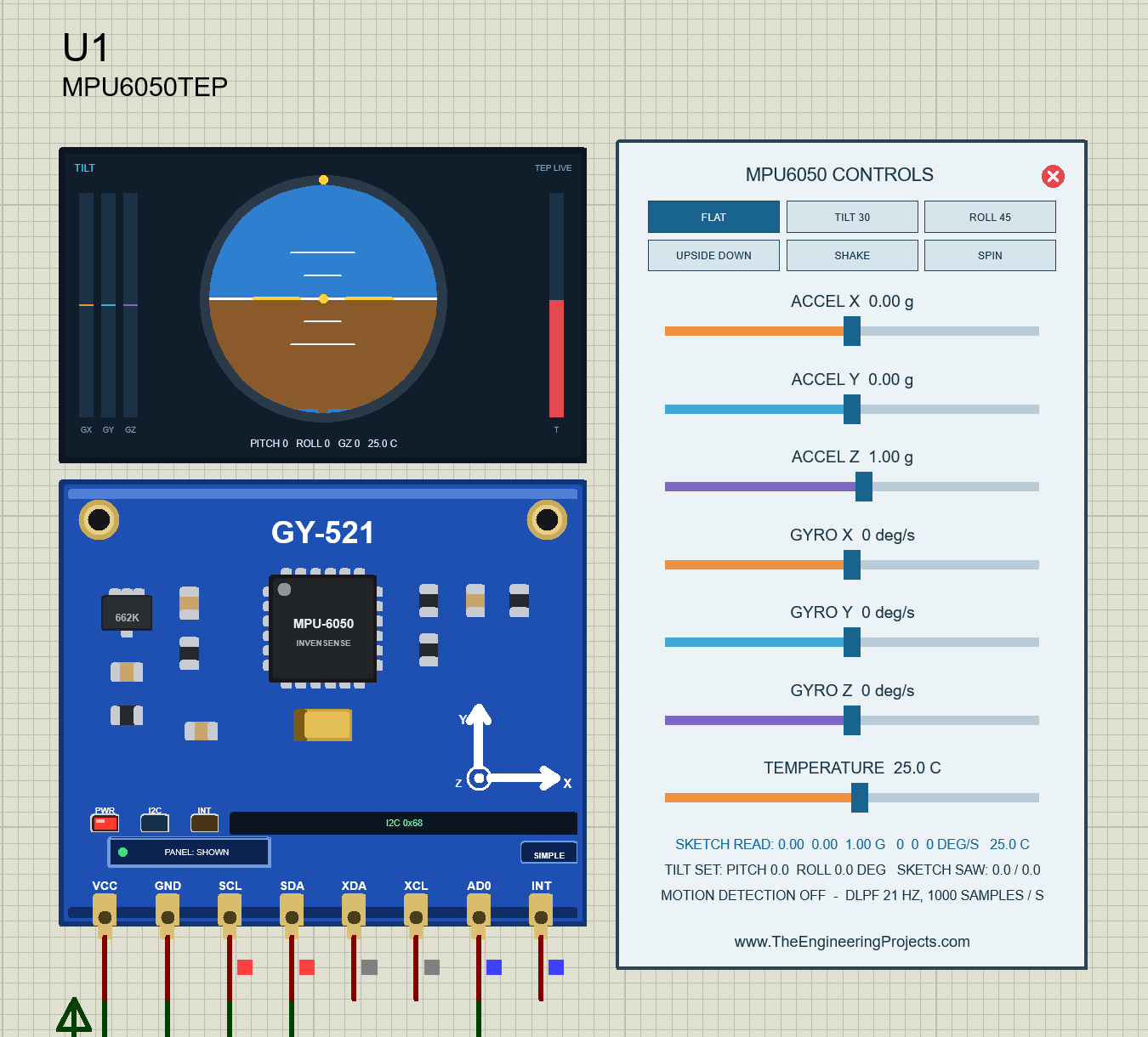
We drew the sensor as a clean TEP board in the royal blue of the GY-521: two gold mounting holes, the MPU-6050 in the centre with the tantalum capacitor below it, the 662K regulator, the X / Y / Z axis glyph and the big GY-521 title. Here is U1, the Simple device, lying flat:
GY-521 or MPU6050?
You see two names on the part, and both are right. MPU-6050 is the chip, InvenSense's motion sensor in the middle of the board, so the chip reads MPU-6050 INVENSENSE. GY-521 is the name of the blue breakout board that carries the chip, its regulator, its small parts and the 8-pin header, so the board title reads GY-521, as on the real module. In Proteus, you still search for "MPU6050".
The Instrument Window
Above the board sits an animated instrument window. The artificial horizon works like the one in an aeroplane: pitch moves it up and down, roll turns it, and a yellow pointer marks the roll on the bezel. Bars for the three gyro axes (GX, GY, GZ) sit on the left, a temperature bar (T) on the right, and PITCH, ROLL, GZ and the temperature are written below. Click the horizon to tilt the sensor.
Pinout
The eight pins keep the v1.0 names, order and places, which are also the order of the real GY-521 header:
| Pin | What it does | Demo connection |
|---|---|---|
| VCC | Power | Supply terminal |
| GND | Ground | GND |
| SCL | I2C clock | Arduino A5 |
| SDA | I2C data | Arduino A4 |
| XDA | Auxiliary I2C data, for an external magnetometer (not simulated) | Not connected |
| XCL | Auxiliary I2C clock (not simulated) | Not connected |
| AD0 | Address: LOW = 0x68, HIGH = 0x69 | GND (0x68) |
| INT | Interrupt output (it also drives the INT LED) | Not connected |
LEDs and Indicators
| Indicator | What it shows |
|---|---|
| Artificial horizon | Pitch and roll of the sensor |
| GX / GY / GZ bars | The rotation rate on each axis |
| T bar | The die temperature |
| PWR LED (red) | Lit while VCC and GND are connected |
| I2C LED (blue) | Flashes for 150 ms with every I2C transaction to this sensor |
| INT LED (amber) | Lit while the INT pin is active |
| I2C 0x68 / 0x69 | The live address, from the AD0 pin |
| PANEL / OPEN PANEL, SIMPLE / ADVANCE | The panel button and the device badge |
The three LEDs are a TEP addition: the real GY-521 has only a small power LED.
Component Properties
| Property | Meaning | Default |
|---|---|---|
| AX, AY, AZ | The acceleration at the start in g, -16 to 16 (gravity included) | 0, 0, 1 (lying flat) |
| GX, GY, GZ | The rotation at the start in deg/s, -2000 to 2000 | 0 |
| TEMPERATURE | The die temperature at the start, -40 to 85 C | 25 |
Every Run starts again from these properties. The panel style comes from the device (Simple or Advance), not from a property.
MPU6050 Simple: The Control Panel on the Sheet
Beside the Simple board sits the MPU6050 CONTROLS panel (on the right of the image above):
| Part | What it does |
|---|---|
| Header, red X | MPU6050 CONTROLS; the X closes the panel |
| Six presets | FLAT, TILT 30, ROLL 45, UPSIDE DOWN, SHAKE and SPIN; the active one turns dark blue |
| Seven sliders | The v1.0 sliders: ACCEL X / Y / Z (-16 to 16 g), GYRO X / Y / Z (-2000 to 2000 deg/s) and TEMPERATURE (-40 to 85 C) |
| SKETCH READ | What your sketch really read over I2C, decoded by the model |
| TILT SET / SKETCH SAW | The tilt you set, against the tilt in the sketch's readings |
| Last line | MOTION DETECTION OFF with the filter and the sample rate (DLPF 21 HZ, 1000 SAMPLES / S), or ON with the threshold, the duration and the number of events |
SKETCH READ is the line to watch: it is not what the sliders say, but what your Arduino got from the chip.
Presets and Tilt
One click sets all three accelerometer values for a position:
| Preset | ACCEL X, Y, Z | Pitch / roll | Tilt alarm |
|---|---|---|---|
| FLAT | 0.00, 0.00, 1.00 g | 0.0 / 0.0 | Off |
| TILT 30 | -0.50, 0.00, 0.87 g | 29.9 / 0.0 | Off (not more than 30) |
| ROLL 45 | 0.00, 0.71, 0.71 g | 0.0 / 45.0 | On |
| UPSIDE DOWN | 0.00, 0.00, -1.00 g | 0.0 / 180.0 | On |
SHAKE adds a shake on top of the current position (see below); try SPIN yourself and watch which bars and readings move. Here is ROLL 45:
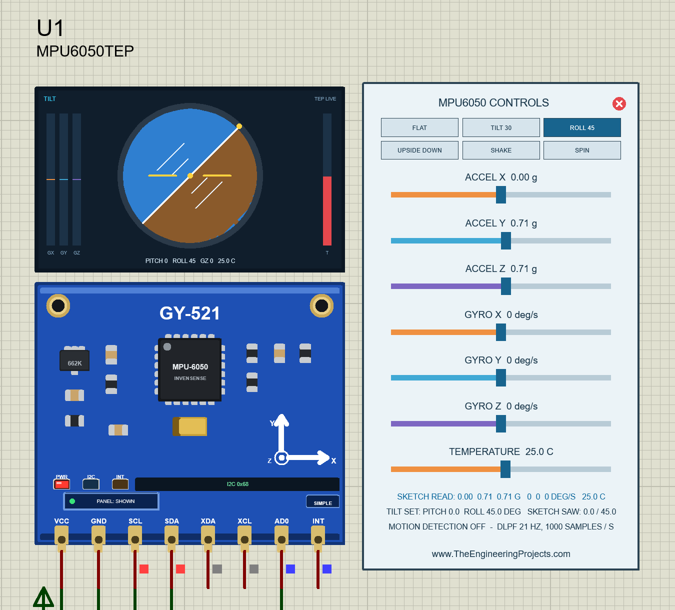
The horizon turns 45 degrees, and the yellow pointer moves along the bezel. Y and Z read 0.71 g each: still 1 g in total, just shared by two axes. The sketch saw 0.0 / 45.0, more than 30 degrees, so UNO 1 lights the tilt alarm LED D1. UPSIDE DOWN turns the world over:
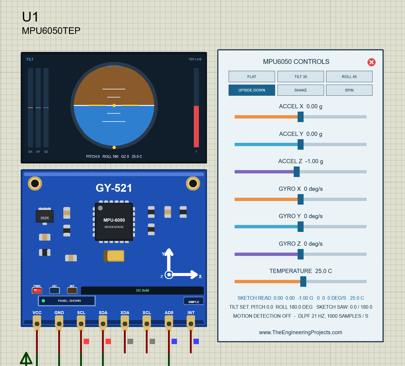
The ground is on top now, and Z reads -1.00 g. The demo's roll = atan2(AY, AZ) = atan2(0, -1) gives 180 degrees, so the tilt alarm stays on.
SHAKE and the Motion Interrupt
Now type MOTION ON on U3 (or click its quick button) and click SHAKE. U1 was lying FLAT when I clicked it:
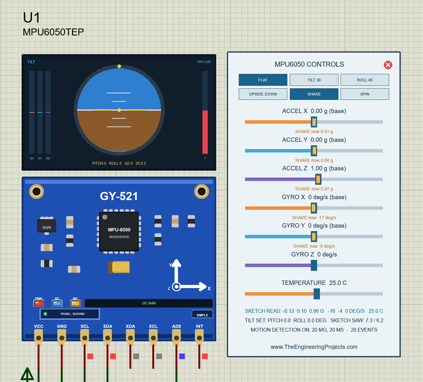
SHAKE is an effect on top of the slider values, so the sliders keep their base values (ACCEL X 0.00 g (base)), and an amber marker with SHAKE now under each one shows what the sensor feels at this moment: 0.01, 0.08 and 0.97 g, -17 and -8 deg/s. The sketch read -0.12, 0.10 and 0.96 g and -16 / -4 deg/s, so its tilt says 7.3 / 6.2 instead of 0.0 / 0.0. That is why pitch and roll from the accelerometer are only right while the sensor holds still. The last line reads MOTION DETECTION ON: 20 MG, 20 MS - 28 EVENTS, the demo's threshold of 10 counts x 2 mg for 20 ms. The amber INT LED lights while the INT pin is active, and the blue I2C LED flashes with the sketch's reads.
Closing the Panel
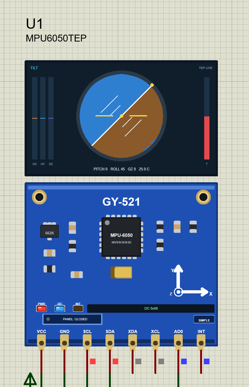
Need room on the sheet? Click the red X: the board button says PANEL: CLOSED with a grey dot, and the sensor keeps running. PANEL brings the panel back. Here, U1 is still at ROLL 45:
MPU6050 Advance: The Pop-Up Sensor Window
The Advance device keeps only the board on the schematic. Here is U2, lying flat:
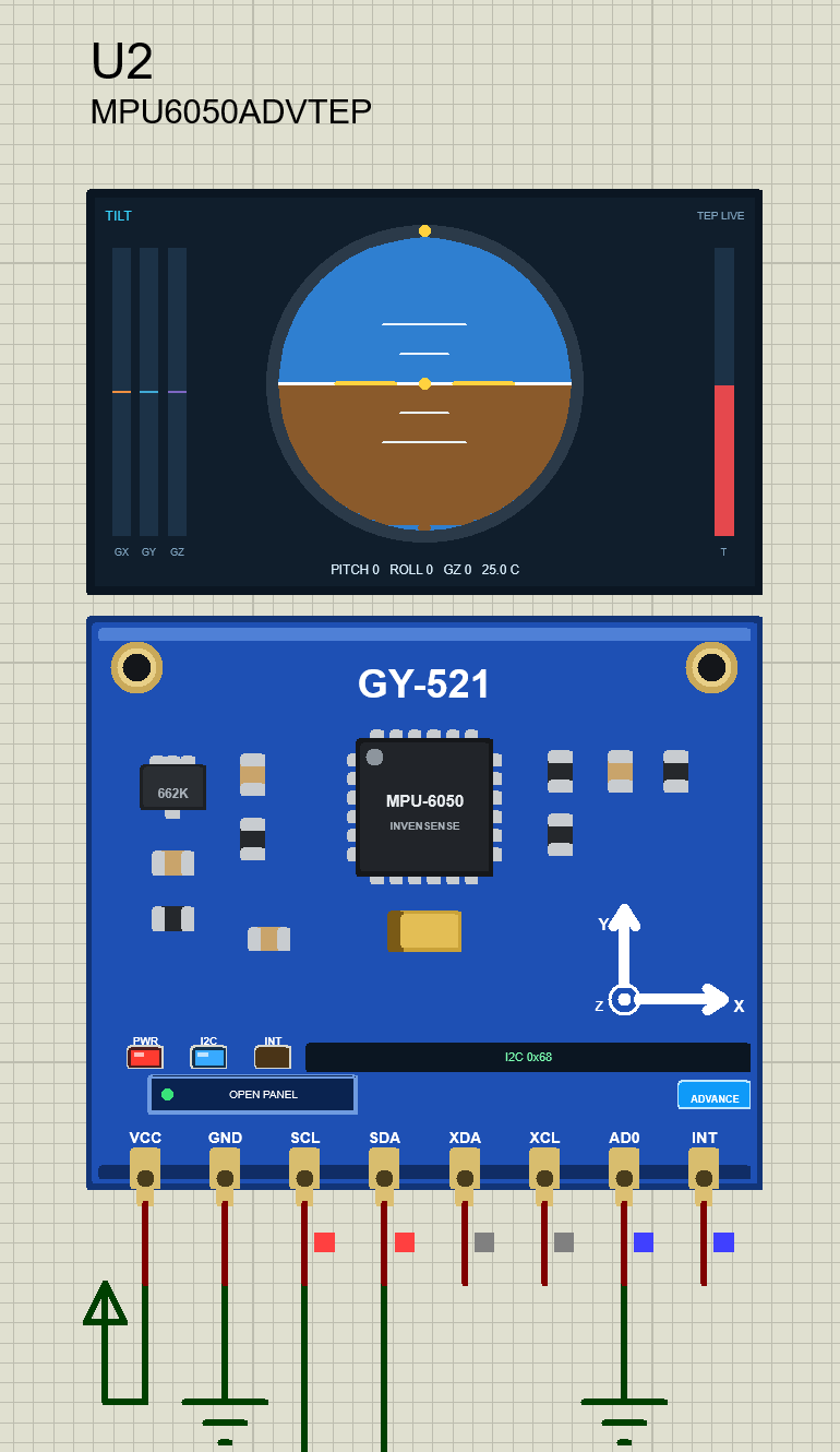
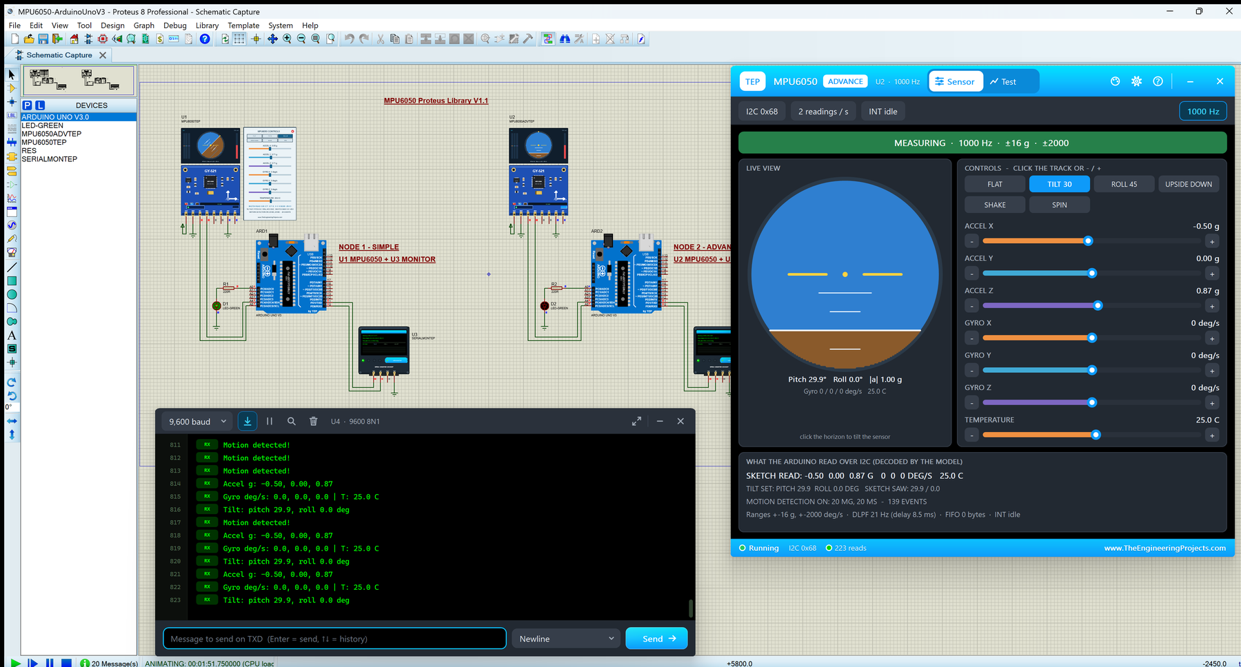
At Run, the "TEP MPU6050 Advance" pop-up opens with the look of our TEP Serial Monitor and no Windows title bar: move it by its header, resize or minimise it, and reopen it with OPEN PANEL. The header shows the state (here U2 · 1000 Hz), the Sensor and Test tabs and the palette (theme), gear (Settings) and ? (Help) icons.
The Sensor Page
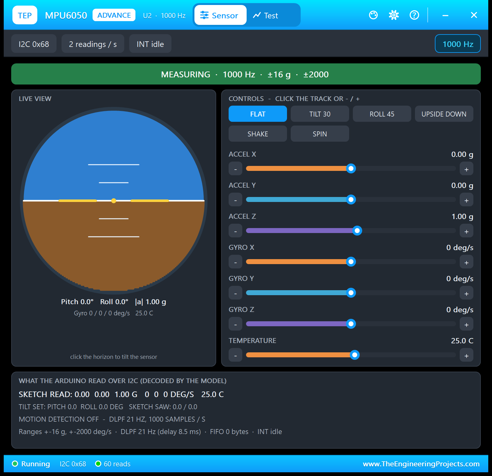
- Toolbar chips: I2C 0x68, 2 readings / s (the demo's 500 ms), INT idle and the sample rate, 1000 Hz.
- Green bar: MEASURING · 1000 Hz · ±16 g · ±2000, the state and the ranges your sketch set.
- LIVE VIEW: a large horizon with pitch, roll, the size of the acceleration |a| (1.00 g at rest), the gyro and the temperature; click it to tilt the sensor.
- CONTROLS: the six presets and a click-slider with - / + for each of the seven inputs.
- WHAT THE ARDUINO READ OVER I2C: SKETCH READ, TILT SET against SKETCH SAW, the motion detector, and the ranges, the DLPF (21 Hz, delay 8.5 ms), the FIFO (0 bytes) and the INT pin.
In the featured image at the top, I clicked TILT 30 on this page. ACCEL X went to -0.50 g and ACCEL Z to 0.87 g, and the horizon reads pitch 29.9°, not 30.0°: cos 30° is 0.866, the preset sets 0.87 g, and atan2(0.50, 0.87) is 29.9°. The model's own TILT SET line says 29.9 too, and so does the sketch. U4 had MOTION ON, so it also printed a few "Motion detected!" lines; while the sensor held still at TILT 30, the readings went on without them. And 29.9 is not more than 30, so the tilt alarm LED D2 stayed off.
The Test Page: Four Measured Sensor Test Tools
The four tools on the Test tab only change the sensor's inputs (and restore them) and watch the I2C reads your Arduino really makes; they never talk to your Arduino. So every number is what the chip and your sketch really did, timed with the simulation clock. Each tool ends with a bold "Good for:" line and a grey line on how it measures. All results below come from U2 with the demo sketch.
1. I2C Check: What Did Your Sketch Write Into the Chip?
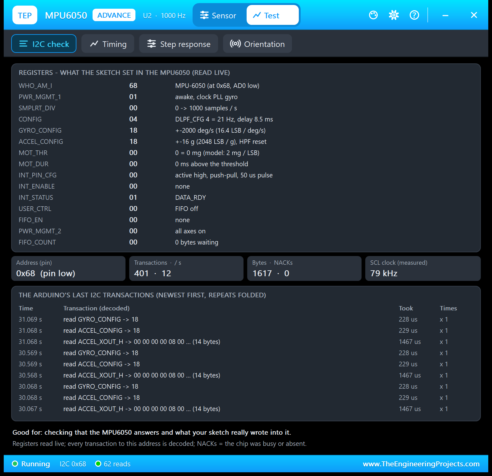
Good for: "checking that the MPU6050 answers and what your sketch really wrote into it." It works live, without a Run button. Read the register table like a checklist:
- WHO_AM_I 68: an MPU-6050, at 0x68 with AD0 low.
- PWR_MGMT_1 01: awake, clocked from the gyro PLL; PWR_MGMT_2 00: all axes on.
- SMPLRT_DIV 00 and CONFIG 04: 1000 samples a second through the 21 Hz filter, delay 8.5 ms.
- GYRO_CONFIG 18 and ACCEL_CONFIG 18: ±2000 deg/s (16.4 LSB per deg/s) and ±16 g (2048 LSB per g).
- MOT_THR, MOT_DUR and INT_ENABLE 00: motion detection was off on U2 at that moment; INT_STATUS 01: the data-ready flag.
- USER_CTRL, FIFO_EN and FIFO_COUNT 00: the FIFO is off and empty.
Below the table: the address 0x68 (pin low), 401 transactions (12 a second), 1617 bytes with 0 NACKs, and the SCL clock, measured on the pin: 79 kHz (the sketch leaves Wire at its default clock). The last transactions show one demo reading every 0.5 s: the 14 data bytes from ACCEL_XOUT_H in 1467 us (accelerometer, temperature and gyro in one burst), then ACCEL_CONFIG and GYRO_CONFIG in about 228 us each, because the Adafruit library reads both ranges again in every getEvent() to scale the raw values. Right after Run, the same list shows the set-up writes, such as "write CONFIG = 04" (21 Hz) and "write ACCEL_CONFIG = 18" (±16 g).
2. Timing: How Often Is There New Data?
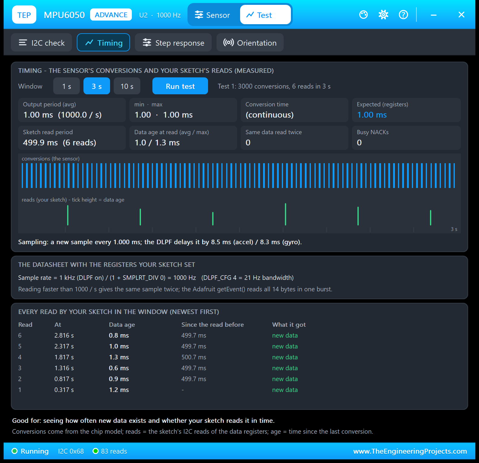
Good for: "seeing how often new data exists and whether your sketch reads it in time." Choose a 1, 3 or 10 s window and click Run test. In 3 s, the sensor made 3000 conversions, one every 1.00 ms (1000.0 a second, min and max 1.00 ms), exactly what the registers expect: 1 kHz / (1 + SMPLRT_DIV 0). The sketch read 6 times, every 499.9 ms. The data it got was 1.0 ms old on average (1.3 ms at most), it never read the same sample twice, and there were no busy NACKs.
The list at the bottom shows every read: at 0.317 s, 0.817 s, 1.316 s and so on, 499.7 to 500.7 ms apart, each one "new data". The line under the timeline adds the filter: the DLPF delays every sample by 8.5 ms (accelerometer) and 8.3 ms (gyroscope). So the demo reads one sample in 500, and a sketch that read more than 1000 times a second would get the same sample twice.
3. Step Response: How Quickly Does a Change Reach Your Sketch?
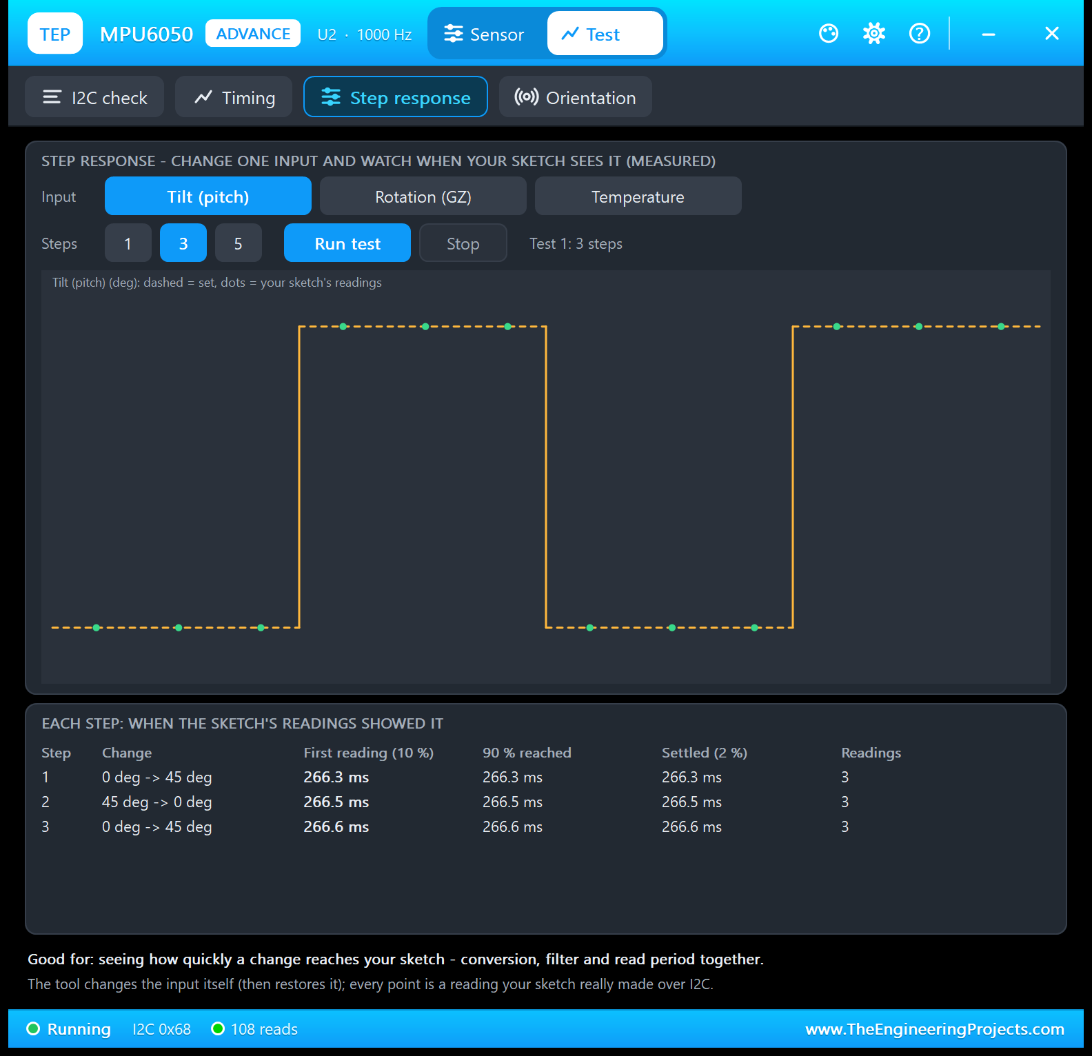
Good for: "seeing how quickly a change reaches your sketch - conversion, filter and read period together." Choose the tilt (pitch 0 to 45 degrees), the rotation (GZ 0 to 250 deg/s) or the temperature (25 to 40 C), and 1, 3 or 5 steps of 1.5 s each. The tool steps the input itself, restores it afterwards, and plots every reading your sketch made: the dashed line is the set value, the dots are the readings.
| Step | Change | First reading (10 %) | 90 % reached | Settled (2 %) | Readings |
|---|---|---|---|---|---|
| 1 | 0 to 45 deg | 266.3 ms | 266.3 ms | 266.3 ms | 3 |
| 2 | 45 to 0 deg | 266.5 ms | 266.5 ms | 266.5 ms | 3 |
| 3 | 0 to 45 deg | 266.6 ms | 266.6 ms | 266.6 ms | 3 |
The three columns are the same in every step: the first reading after the step already had the whole change. The 8.5 ms filter delay is tiny next to the demo's 500 ms reads, so the 266 ms is simply how long the sketch waited for its next read. To see the filter itself, type FILTER 5 (19 ms delay) and RATE 200 on U4 and run it again.
4. Orientation: Does Your Pitch and Roll Maths Work Everywhere?
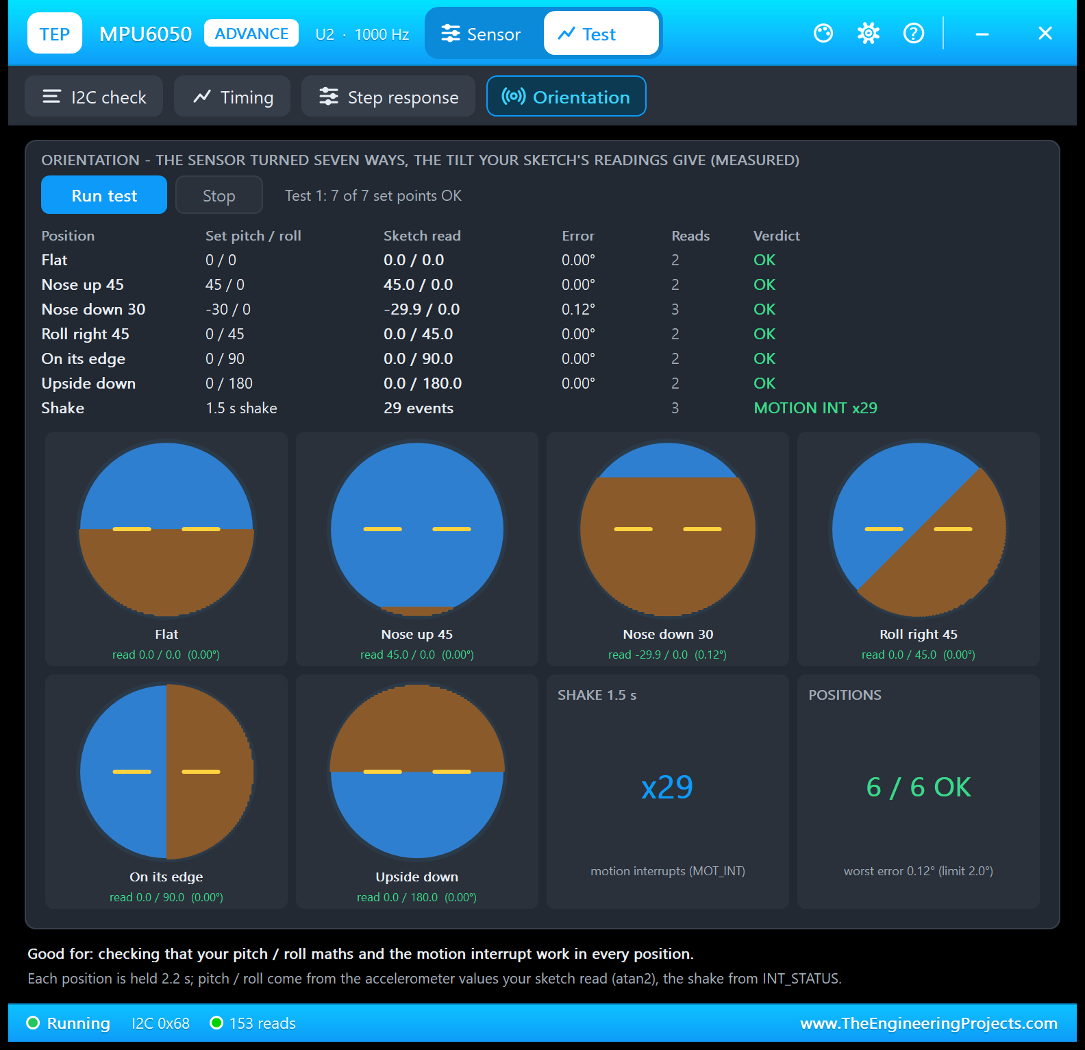
Good for: "checking that your pitch / roll maths and the motion interrupt work in every position." The tool holds the sensor flat, nose up 45, nose down 30, rolled right 45, on its edge and upside down, 2.2 s each, and computes pitch and roll from the accelerometer values your sketch read (atan2), with a small horizon for each. Then it shakes the sensor for 1.5 s and counts the motion interrupts in INT_STATUS.
The result: 7 of 7 set points OK. Five positions read exactly (error 0.00°); nose down 30 read -29.9 (0.12°), like TILT 30 on the Sensor page, far inside the 2.0° limit. The shake fired 29 motion interrupts. Type MOTION ON on U4 first: without it, the shake cell says "motion INT off (type MOTION ON)".
Settings and Help
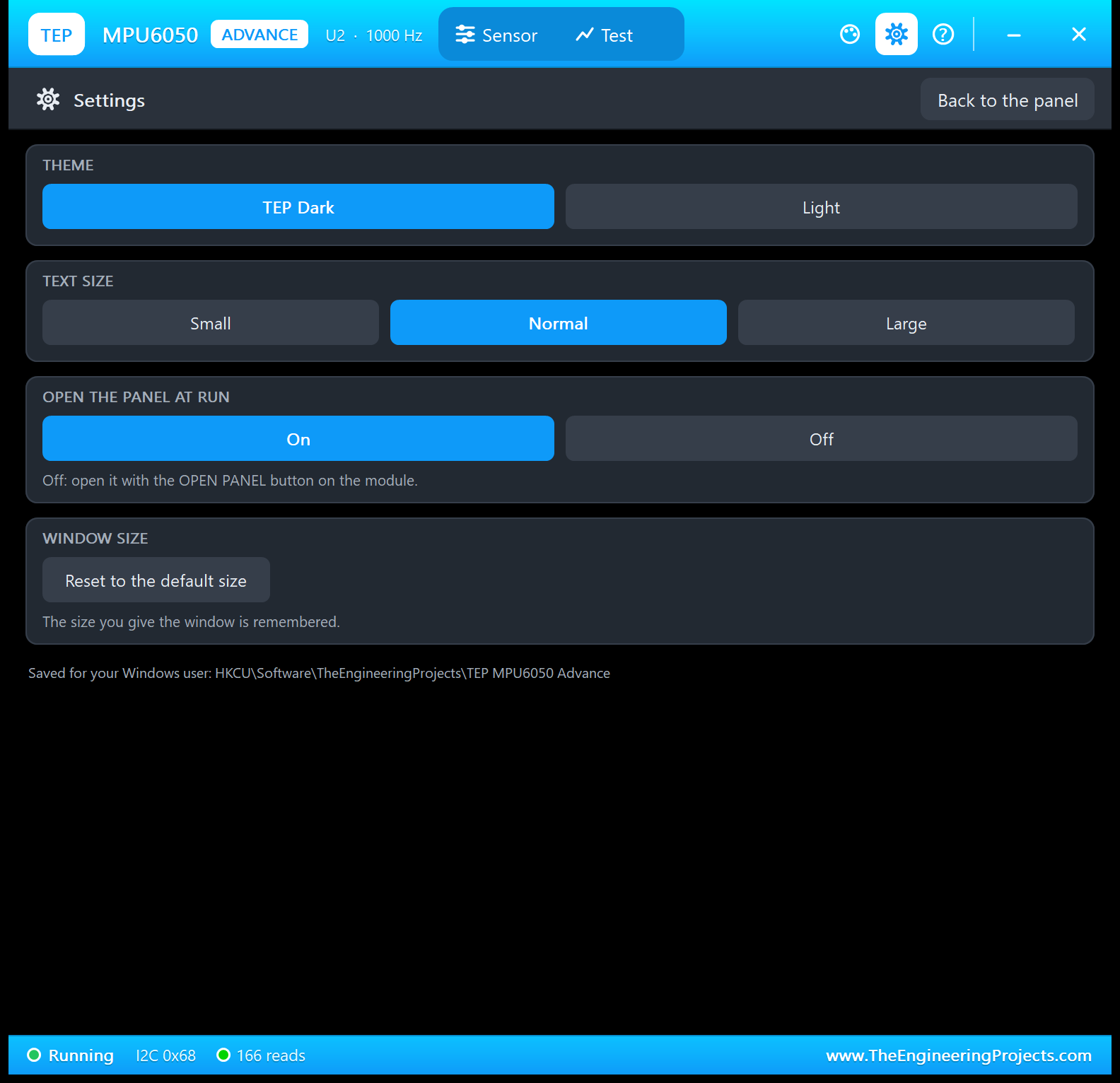
The gear opens Settings: theme (TEP Dark or Light), text size, open the panel at Run, and the window size, saved for your Windows user.
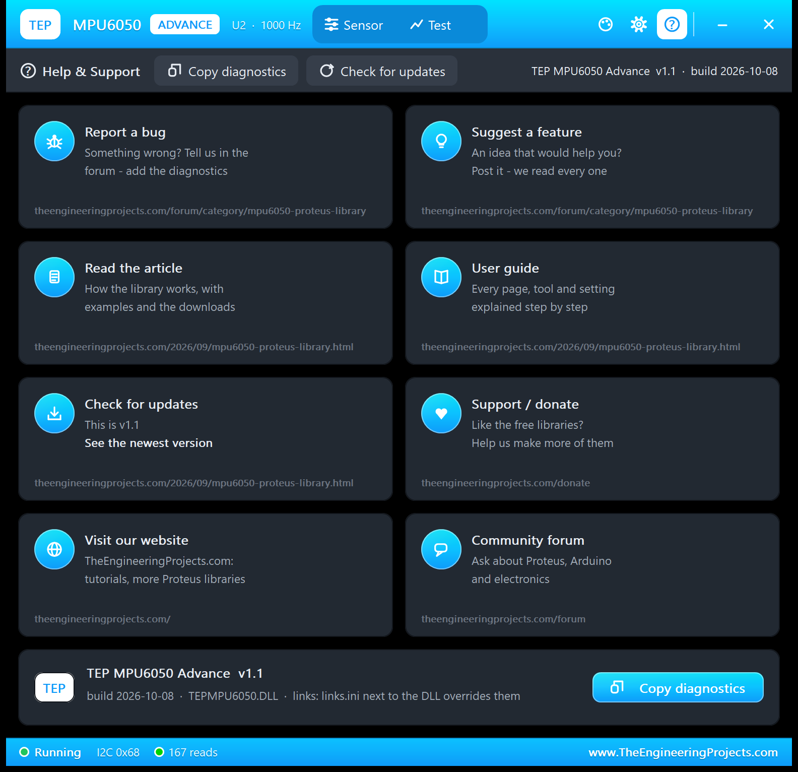
The ? icon opens Help & Support: eight cards with their links (the MPU6050 forum board for bugs and ideas, this article, updates, donate, website, forum), Check for updates, and Copy diagnostics for a bug report: the inputs, what was read, the registers, the last transactions and the test results. A links.ini next to the DLL can change the links.
MPU6050 Tilt Alarm with Arduino in Proteus
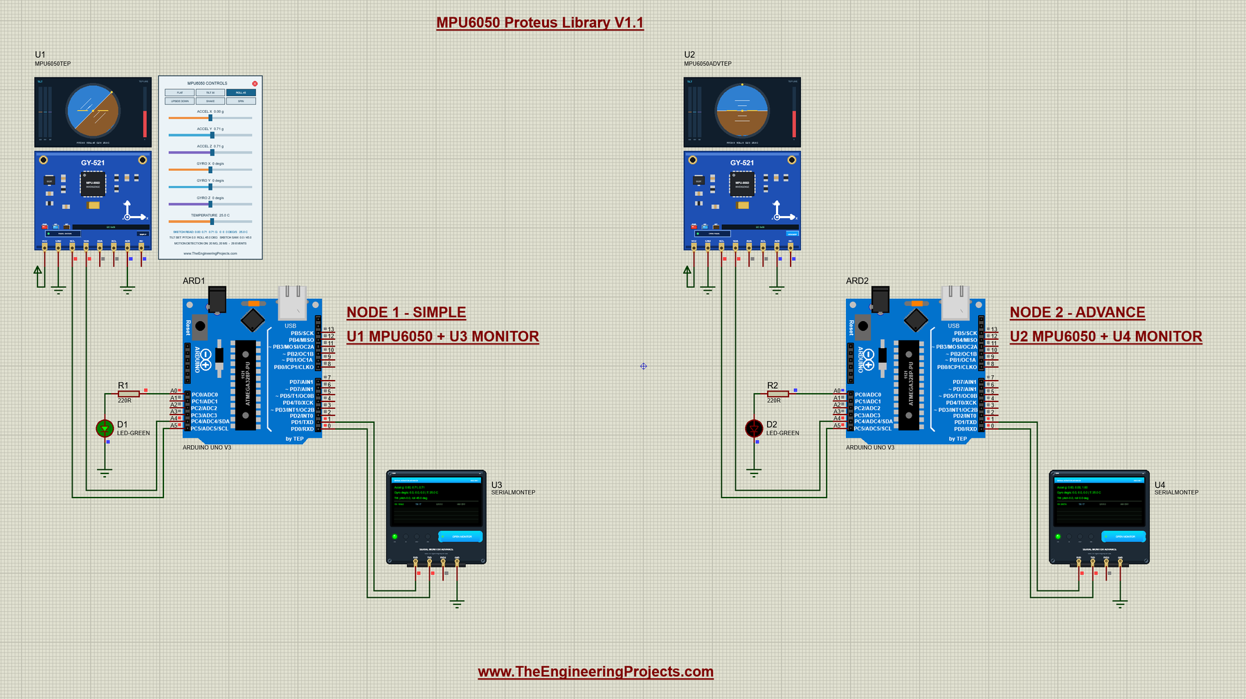
Open MPU6050-ArduinoUnoV3.pdsprj from the Proteus Simulation folder, with MPU6050_Demo.hex and both DLLs beside it. Its two Arduino UNOs from our Arduino Library for Proteus V3.0 run the same HEX file:
- NODE 1 - SIMPLE: UNO 1 (ARD1) with the MPU6050 Simple (U1), the tilt alarm LED D1 on A0 and Serial Monitor U3.
- NODE 2 - ADVANCE: UNO 2 (ARD2) with the MPU6050 Advance (U2), the tilt alarm LED D2 on A0 and Serial Monitor U4.
Both sensors have AD0 to ground (0x68); each UNO has its own I2C bus, so that is no conflict.
Wiring
| From | To | Why |
|---|---|---|
| MPU6050 VCC / GND | Supply / ground | Power (the PWR LED lights) |
| MPU6050 SCL / SDA | Arduino A5 / A4 | I2C clock and data |
| MPU6050 AD0 | GND | Address 0x68 |
| MPU6050 XDA / XCL / INT | Not connected | INT is optional: it drives the INT LED and can go to D2 for attachInterrupt |
| LED + 220 Ω | A0 to GND | The tilt alarm LED |
| Serial Monitor RXD / TXD / GND | Arduino D1 / D0 / ground | Shows what the Arduino prints, sends what you type |
| Serial Monitor RXD2 | Not connected | I2C has no serial line to watch |
A4 and A5 are the UNO's I2C pins (see our Introduction to Arduino UNO). The Wire library turns on the UNO's internal pull-ups, so the simulation needs no external pull-up resistors; a real GY-521 has its own on board.
The Arduino Code
The sketch uses the unmodified Adafruit MPU6050 library (with Adafruit BusIO and Adafruit Unified Sensor), like v1.0:
#include <Wire.h>
#include <Adafruit_MPU6050.h>
Adafruit_MPU6050 sensor;
bool ready=false;
The new v1.1 variables: the LED pin, the print period (RATE), the motion detector and the tilt alarm:
const uint8_t LED_PIN=A0;
unsigned long readEvery=500, lastRead=0, lastPoll=0, ledUntil=0;
bool motionOn=false, tiltLine=true, alarmOn=false;
uint8_t motionThreshold=10;
In setup(), begin(0x68) finds the sensor at the AD0-low address, and the sketch sets the widest ranges and the 21 Hz filter, as in v1.0:
  Serial.begin(9600); Wire.begin(); Wire.setWireTimeout(25000,true);
  pinMode(LED_PIN,OUTPUT); digitalWrite(LED_PIN,LOW);
  ready=sensor.begin(0x68);
  if(!ready) { Serial.println(F("MPU6050 not found. Check power, A4/SDA, A5/SCL and AD0.")); return; }
  sensor.setAccelerometerRange(MPU6050_RANGE_16_G);
  sensor.setGyroRange(MPU6050_RANGE_2000_DEG);
  sensor.setFilterBandwidth(MPU6050_BAND_21_HZ);
The loop reads every RATE ms. getEvent() fills three events; the acceleration comes in m/s², so the sketch divides by 9.80665 to print g:
  if(now-lastRead>=readEvery) {
    lastRead=now;
    sensors_event_t a,g,t; sensor.getEvent(&a,&g,&t);
    Serial.print(F("Accel g: ")); Serial.print(a.acceleration.x/9.80665,2);
The gyro comes in rad/s, so it is multiplied by 57.29578 (180 / π) to print deg/s:
Serial.print(F("Gyro deg/s: ")); Serial.print(g.gyro.x*57.29578,1);Then the new tilt line, with the atan2 formulas from above:
    const float ax=a.acceleration.x, ay=a.acceleration.y, az=a.acceleration.z;
    const float pitch=atan2(-ax,sqrt(ay*ay+az*az))*57.29578, roll=atan2(ay,az)*57.29578;
The tilt alarm switches at more than 30 degrees, and its message comes only when it changes:
    const bool tilted=fabs(pitch)>30 || fabs(roll)>30;
    if(tilted!=alarmOn) { alarmOn=tilted; Serial.println(alarmOn ? F("Tilt alarm: ON (more than 30 deg)") : F("Tilt alarm: off")); }
MOTION ON sets up the motion detector with the 0.63 Hz high-pass filter, the threshold (10 by default), 20 ms, and a latched, active-high INT pin:
    sensor.setHighPassFilter(MPU6050_HIGHPASS_0_63_HZ);
    sensor.setMotionDetectionThreshold(motionThreshold);
    sensor.setMotionDetectionDuration(20);
    sensor.setInterruptPinLatch(true);
    sensor.setInterruptPinPolarity(false);
    sensor.setMotionInterrupt(true);
The loop asks the chip every 50 ms if the motion bit is set, and keeps the LED on for 1 s after each event:
  if(motionOn && now-lastPoll>=50) {
    lastPoll=now;
    if(sensor.getMotionInterruptStatus()) { Serial.println(F("Motion detected!")); ledUntil=now+1000; }
  }
digitalWrite(LED_PIN,(alarmOn || millis()<ledUntil) ? HIGH : LOW);HELP prints two lines, so it fits the Serial Monitor's Simple interface:
void help() {
  Serial.println(F("Commands: HELP, STATUS, RANGE 2|4|8|16, GYRO 250|500|1000|2000,"));
  Serial.println(F("  FILTER 260|184|94|44|21|10|5, RATE ms, MOTION ON [thr] | OFF, TILT ON | OFF"));
}
The settings live in the chip and in RAM, so a reset brings back the start values. To change the sketch, export a new HEX file and load it into both UNOs; see How to get the HEX file from Arduino. New to Arduino? Start with our Arduino Tutorial for Beginners.
Serial Monitor Commands
| Command | What it does |
|---|---|
| HELP | The command list (two lines) |
| STATUS | Two lines: the ranges, the filter and the print period; the motion detector and the tilt alarm |
| RANGE 2 | 4 | 8 | 16 | The accelerometer range in ±g |
| GYRO 250 | 500 | 1000 | 2000 | The gyroscope range in ±deg/s |
| FILTER 260 | 184 | 94 | 44 | 21 | 10 | 5 | The digital low-pass filter in Hz |
| RATE ms | The print period, 100 to 10000 ms (default 500) |
| MOTION ON [thr] / MOTION OFF | The motion interrupt: high-pass 0.63 Hz, threshold 10 by default, 20 ms, latched |
| TILT ON / TILT OFF | The tilt line under each reading |
How to Run the Demo
- Press Run. Both Serial Monitors (9600 baud) and U2's pop-up open; the PWR LEDs light, and the I2C LEDs flash with every reading.
- On U1's panel, click TILT 30, ROLL 45 (D1 lights), UPSIDE DOWN and FLAT, or click the horizon.
- Click STATUS on U3, then MOTION ON, and click SHAKE on U1's panel.
- On U2's Sensor page, try the presets; type MOTION ON on U4, then run the four tools on the Test tab.
- Close U2's window and open it again with OPEN PANEL; close U1's panel with its red X and open it with PANEL.
MPU6050 Proteus Simulation Results
The Serial Monitor in Its Simple Interface
Both monitors in this demo run in the Simple interface of our TEP Serial Monitor, as in every monitor screenshot here. Only the log, the send box and one slim toolbar row stay visible (baud rate, follow, pause, search and clear), so the window stays small.
- Switch to it: right-click the log and choose Simple interface, or press Ctrl+Shift+U.
- Back to the full view: click the corner button (the expand arrows at the top right), press Esc or Ctrl+Shift+U, or right-click and choose Full interface.
- Your choice is remembered.
Type commands such as STATUS or MOTION ON in the send box and press Enter; the quick buttons (STATUS, MOTION ON, RATE 200, HELP) come back with the full view. Every line of the v1.1 sketch is 80 characters or less, so it fits this small window. Read all about the monitor in TEP Serial Monitor Advance for Proteus.
Start-Up
After Run, U3 prints the v1.0 line, the new v1.1 line and then a reading every 500 ms: the v1.0 accelerometer and gyro lines plus the new tilt line:
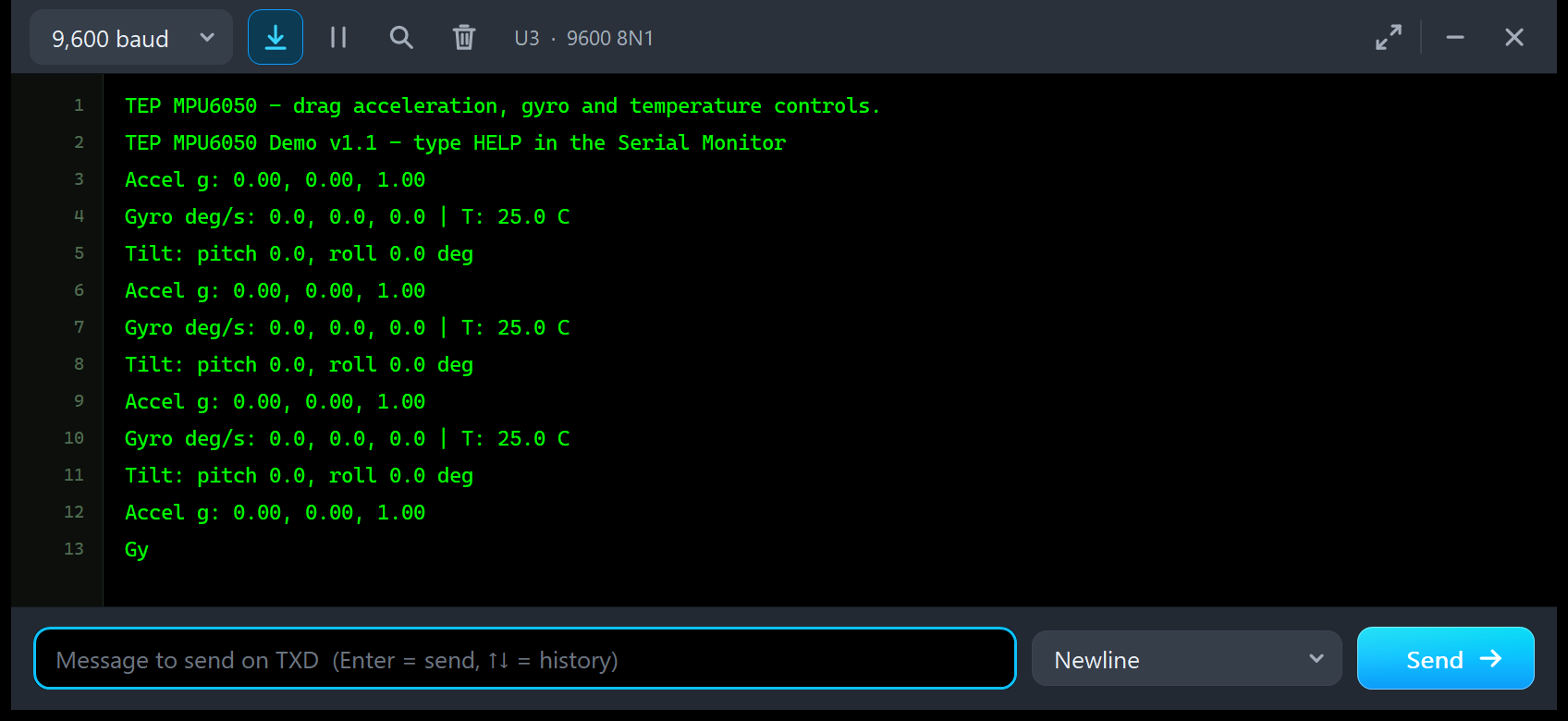
TEP MPU6050 - drag acceleration, gyro and temperature controls.
TEP MPU6050 Demo v1.1 - type HELP in the Serial Monitor
Accel g: 0.00, 0.00, 1.00
Gyro deg/s: 0.0, 0.0, 0.0 | T: 25.0 C
Tilt: pitch 0.0, roll 0.0 deg
Accel g: 0.00, 0.00, 1.00
Gyro deg/s: 0.0, 0.0, 0.0 | T: 25.0 C
Tilt: pitch 0.0, roll 0.0 deg
Flat at 25 C: 0, 0 and 1 g, no rotation, pitch and roll 0.0. The "Gy" at the bottom of the screenshot is the next reading, still on its way at 9600 baud.
ROLL 45: The Tilt Alarm
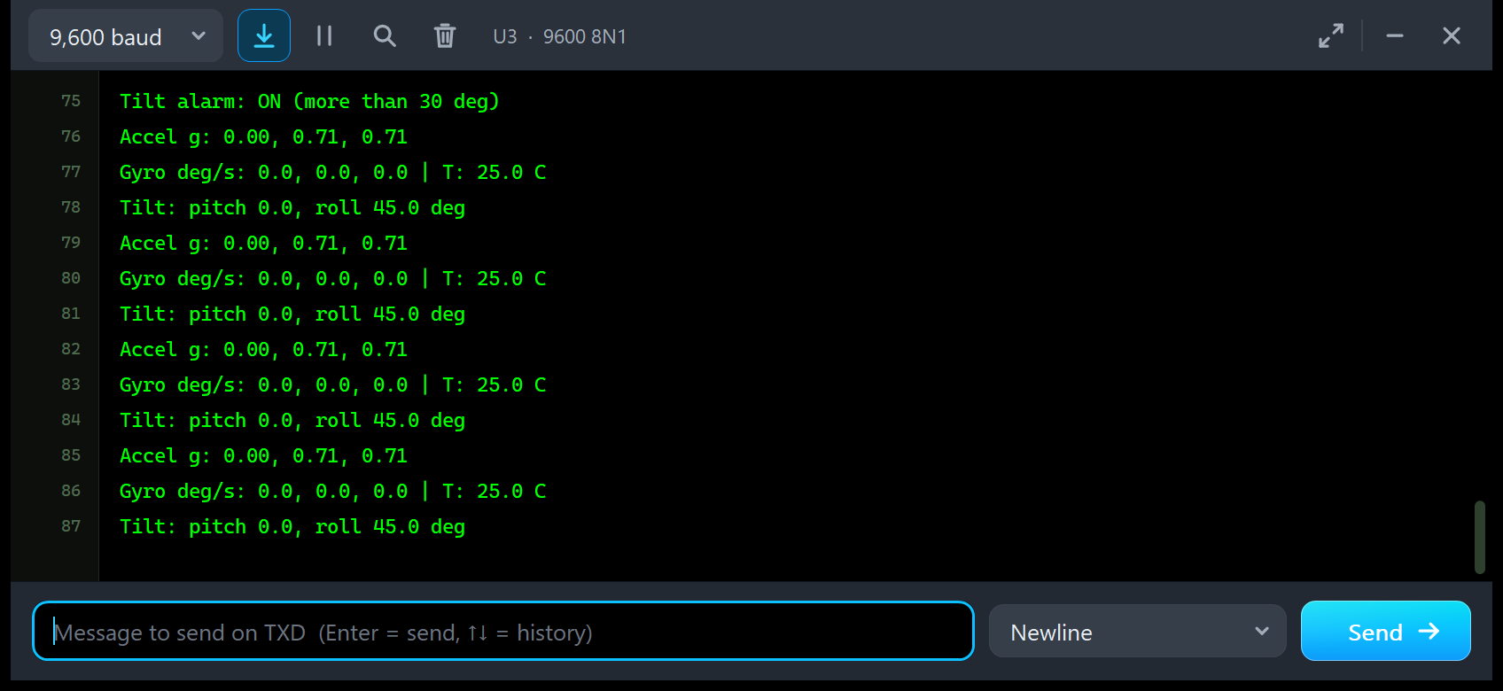
Tilt alarm: ON (more than 30 deg)
Accel g: 0.00, 0.71, 0.71
Gyro deg/s: 0.0, 0.0, 0.0 | T: 25.0 C
Tilt: pitch 0.0, roll 45.0 deg
One click on ROLL 45, and the sketch prints "Tilt alarm: ON (more than 30 deg)" once and lights D1; then the readings go on with 0.00, 0.71, 0.71 g and a roll of 45.0. The alarm line comes only when the alarm changes, so it does not fill the log; FLAT prints "Tilt alarm: off".
STATUS
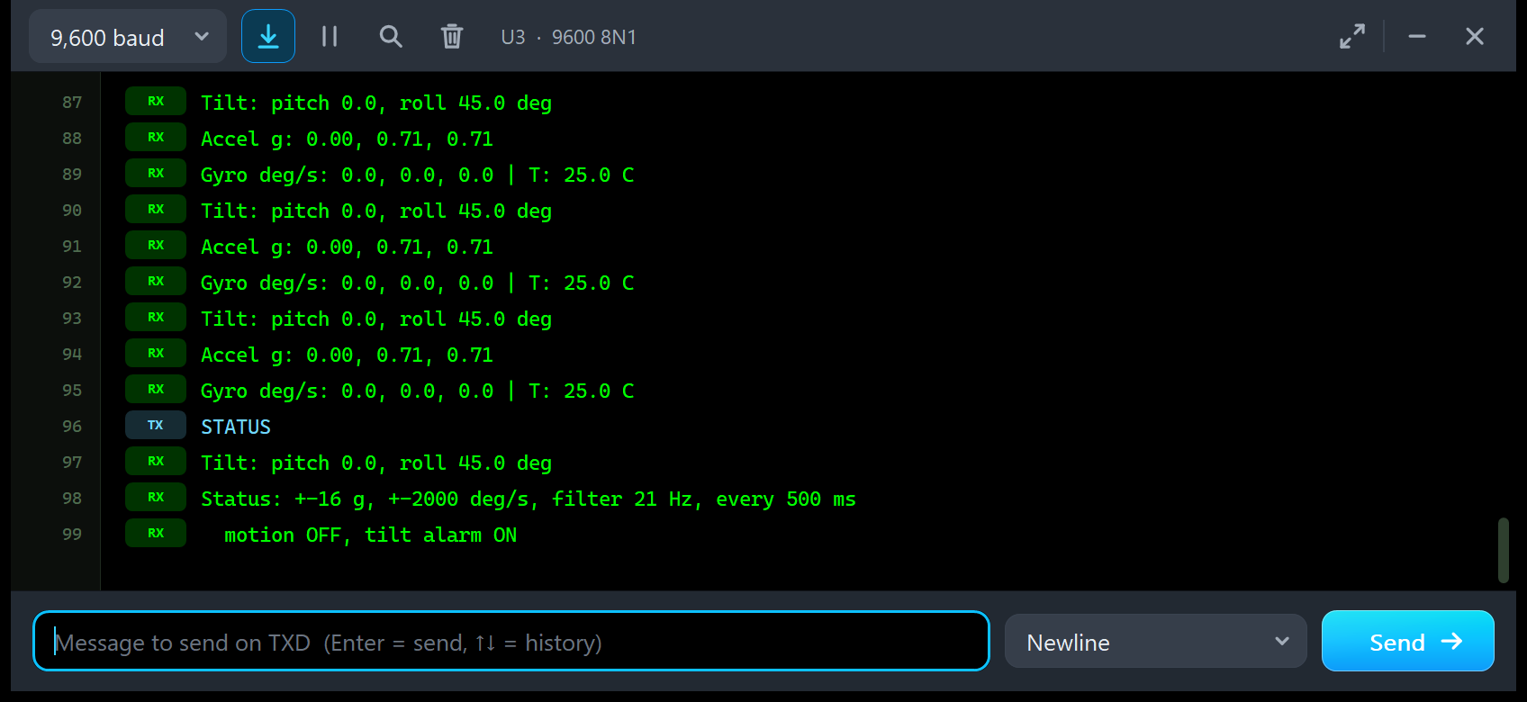
Gyro deg/s: 0.0, 0.0, 0.0 | T: 25.0 C
STATUS
Tilt: pitch 0.0, roll 45.0 deg
Status: +-16 g, +-2000 deg/s, filter 21 Hz, every 500 ms
  motion OFF, tilt alarm ON
STATUS gives the ranges, the filter and the print period, then the motion detector and the alarm (here OFF and ON). The reading the sketch was printing finishes first, so its Tilt line comes before the answer.
MOTION ON
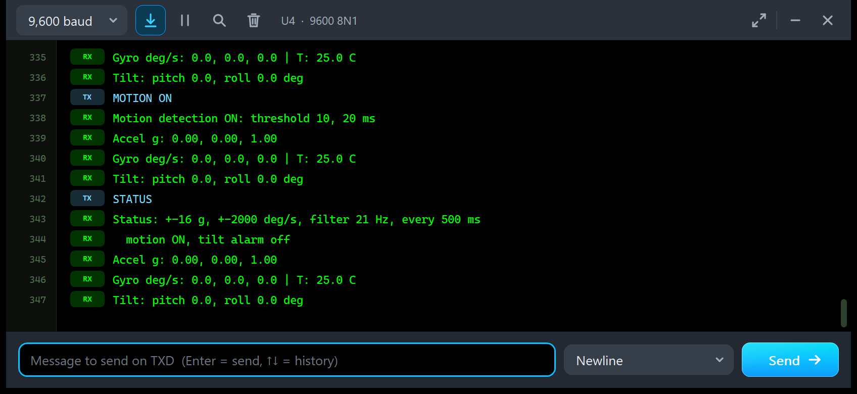
Tilt: pitch 0.0, roll 0.0 deg
MOTION ON
Motion detection ON: threshold 10, 20 ms
Accel g: 0.00, 0.00, 1.00
Gyro deg/s: 0.0, 0.0, 0.0 | T: 25.0 C
Tilt: pitch 0.0, roll 0.0 deg
STATUS
Status: +-16 g, +-2000 deg/s, filter 21 Hz, every 500 ms
  motion ON, tilt alarm off
Threshold 10 means 10 counts of 2 mg, that is 20 mg, for 20 ms, as the Sensor page showed. Lying flat, nothing happens: a steady position is not motion.
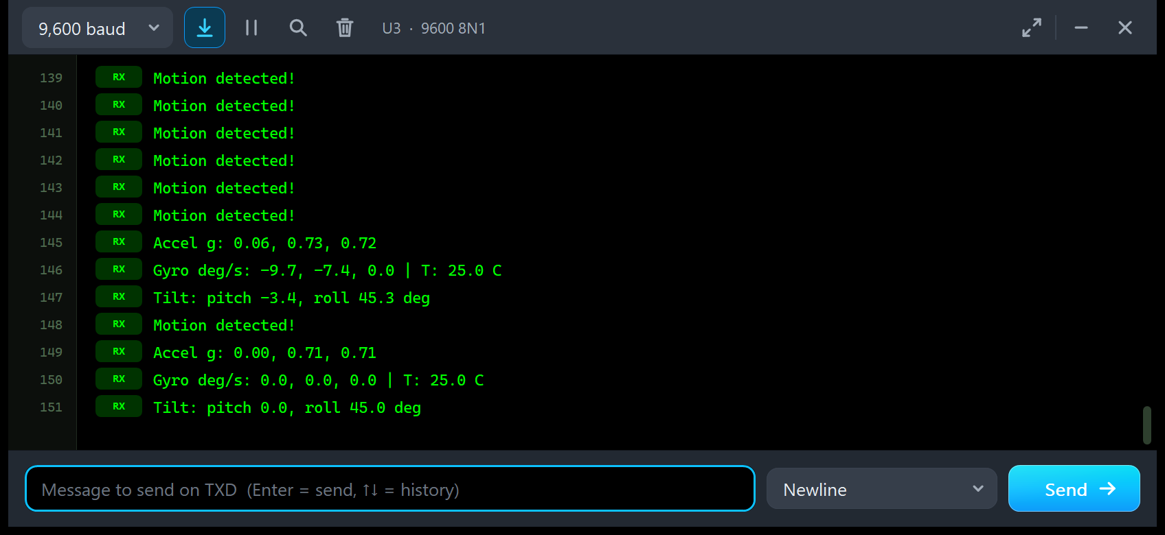
SHAKE: Motion Detected!
Motion detected!
Motion detected!
Motion detected!
Motion detected!
Motion detected!
Motion detected!
Accel g: 0.06, 0.73, 0.72
Gyro deg/s: -9.7, -7.4, 0.0 | T: 25.0 C
Tilt: pitch -3.4, roll 45.3 deg
Motion detected!
Accel g: 0.00, 0.71, 0.71
Gyro deg/s: 0.0, 0.0, 0.0 | T: 25.0 C
Tilt: pitch 0.0, roll 45.0 deg
With MOTION ON on U3, I clicked SHAKE at ROLL 45. The sketch asks the chip every 50 ms, so a shake prints a row of "Motion detected!" lines. A reading in the middle of the shake shows the extra movement: 0.06, 0.73, 0.72 g, -9.7 and -7.4 deg/s, and a tilt of -3.4 / 45.3. When the shake ends, the readings are back at 0.00, 0.71, 0.71 g and a roll of 45.0.
Troubleshooting
- "MPU6050 not found. Check power, A4/SDA, A5/SCL and AD0.": check VCC / GND (the PWR LED must be lit and the board must show I2C 0x68), SDA on A4, SCL on A5, and that AD0 matches the address in
begin()(0x68 = AD0 low); then restart the simulation. - The values do not change: the blue I2C LED must flash with every read. A slider change shows at the sketch's next read, and through the low-pass filter (FILTER 5 delays it by 19 ms).
- Z reads 1 g although nothing moves: correct, that is gravity. AX = AY = AZ = 0 is free fall.
- "Motion detected!" never comes: type MOTION ON first; the motion detector only sees changes, so a steady tilt is not motion. Click SHAKE.
- TILT 30 does not light the LED: correct; it reads 29.9 degrees, and the alarm needs more than 30.
- The part is not simulated, no panel or no monitor window: TEPMPU6050.DLL or TEPSERIALMON.DLL is missing from MODELS and the project folder; click OPEN MONITOR on a closed monitor.
- The Advance pop-up does not appear: click OPEN PANEL on the board, or turn "Open the panel at Run" back on in Settings.
- No red X, or the board looks like v1.0: the design still holds the v1.0 symbol; replace TEPMPU6050.LIB, delete TEPMPU6050.IDX and re-pick the part.
- Your own sketch uses SoftwareSerial to receive: Proteus 8.5 cannot receive with SoftwareSerial; use the hardware Serial, as the demo does, or AltSoftSerial.
Things to Know Before Using a Real GY-521
The demo sketch uses only Wire and the Adafruit libraries, so it runs on a real UNO and GY-521, too. Keep in mind:
- Supply: the GY-521 has a 3.3 V regulator (662K), so feed VCC with 5 V or 3.3 V from the Arduino. The MPU-6050 itself is a 3.3 V part. In the simulation, VCC goes to a supply terminal.
- Pull-ups: the GY-521 has its own I2C pull-ups (2.2 k or 10 k to 3.3 V on most boards), so A4 / A5 need nothing else, and a 5 V UNO reads the 3.3 V levels correctly.
- Address: AD0 has a 4.7 k pull-down on the board (0x68); tie AD0 to VCC for 0x69. Two MPU6050s on one bus need different AD0 levels.
- XDA / XCL are the MPU-6050's auxiliary I2C master, for a magnetometer; they are not simulated.
- INT is optional; wire it to D2 if your sketch uses
attachInterrupt. - Noise, offsets and drift: a real sensor has them, so calibrate it, and expect an angle summed from the gyro to drift; the model gives exact values.
Limitations of the Simulation
- Not modelled: the DMP (motion processing firmware), the auxiliary I2C master, the self-test, the offset registers, the cycle and low-power wake-up modes, zero-motion and free-fall detection, noise, offsets and drift. The MOT_THR scale (2 mg per count) is a model value.
- The model is our own implementation, written from the MPU-6000 / MPU-6050 product specification and register map; it contains no InvenSense code.
- Licences: BSD for the Adafruit MPU6050 library 2.2.9, MIT for Adafruit BusIO 1.17.4 and Apache License 2.0 for Adafruit Unified Sensor 1.1.15. The HEX file also contains the Arduino AVR core 1.8.6, which includes LGPL-licensed code; its source code is on GitHub.
- Tested in Proteus 8.5 on 8 Oct 2026 (the demo, both panels, the four tools, a v1.0 design and every screenshot here) and with 4,928 automatic PC checks, all passed, 27 of them with the real demo sketch and the unmodified Adafruit library on two UNOs; the unchanged v1.0 test passed too. Proteus 7 is not supported.
Need temperature, humidity and pressure next to the motion? See our BME280 Sensor Library for Proteus. Measuring light? Try our BH1750 Light Sensor Library for Proteus. To send your readings to another Arduino by radio, add our HC-12 Library for Proteus.
So, that was all about the MPU6050 Sensor Library for Proteus V1.1. I hope the live horizon, the presets, the motion interrupt and the four test tools make the MPU6050 much easier to understand, so your tilt alarm or motion project works the first time you wire a real GY-521. If you use the MPU6050 Sensor Library for Proteus in a project, please share your feedback in the comments or in our forum, and if you have any questions, ask in the comments and I will help you out. Till the next tutorial, take care and have fun!