Hello friends, I hope you are doing well. This is the thirteenth tutorial in our series on how to create a Proteus library. In the previous tutorial, Proteus Simulation Models Explained, we met the four kinds of simulation model and saw that our Traffic Light Module still has none: Pick Devices labels it No Simulator Model, and a simulation stops with "No model specified". Today, we give it its first working model. Our topic is how to add a SPICE model in Proteus.
We will write a small SPICE subcircuit for the module, attach it to our part with four properties in the Make Device wizard, copy the model file to the right folder and test the result with ammeters at 5 V and at 3.3 V. Then we make three typical mistakes on purpose and read the messages Proteus gives for each, pack the model into a SPICE model library with Labcenter's own tool, and look at the other ways Proteus accepts SPICE models.
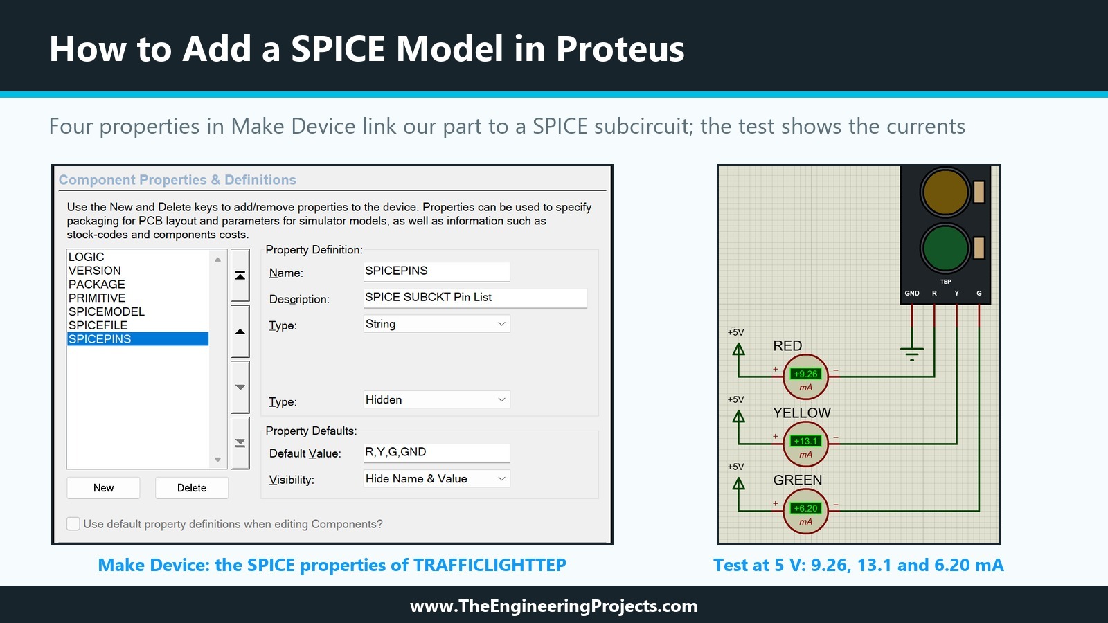
Everything shown here was done in Proteus 8.5 Professional on our PC, and every number in this tutorial was read from the simulation. The picture below shows the two halves of the job: the SPICE properties in Make Device on the left, and the test circuit with the currents our model draws on the right.
What Is a SPICE Model in Proteus?
PROSPICE, the simulator inside Proteus, is based on Berkeley SPICE3F5. That means it understands the same text format as other SPICE programs: a netlist of resistors, capacitors, diodes, transistors and sources, written one element per line. A SPICE model is a piece of such text that describes how a part behaves electrically.
The help points out the consequence: a SPICE model contains no graphics at all, so it cannot be placed on a schematic by itself. Every SPICE part in Proteus is therefore two things working together, a library part with a symbol and pins, which we built in the earlier tutorials, and a model file, which tells the simulator what happens between those pins. A handful of properties connect the two.
SUBCKT Models and MODEL Cards
SPICE models come in two forms. A SUBCKT block is a small circuit with numbered connection nodes, opened by a .SUBCKT line and closed by .ENDS. Manufacturers publish op-amps, regulators and many other chips this way. A MODEL card is a single .MODEL line that lists the parameters of one SPICE primitive, such as a diode or a transistor. Our module is a small circuit with four connections, so it gets a SUBCKT. We will come back to MODEL cards near the end.
Why Our Module Gets a SPICE Model First
Electrically, the Traffic Light Module is simple: each of the pins R, Y and G drives a series resistor and an LED that returns to GND. That is exactly the kind of circuit SPICE handles perfectly. With a SPICE model, an Arduino pin or a power rail connected to our part sees a realistic load, and the simulation can tell us how much current each lamp draws. What a SPICE model cannot do is change the drawing on the screen; we return to that limit after the test.
The Four SPICE Properties of a Proteus Part
As we saw in the previous tutorial, Proteus chooses the model of a part by its property names. A part with a SUBCKT model needs four of them:
| Property | What it holds | Our value |
|---|---|---|
| PRIMITIVE | Tells PROSPICE that the part is simulated by a SPICE subcircuit | ANALOG,SUBCKT |
| SPICEMODEL | The name of the subcircuit, exactly as written on its .SUBCKT line | TLM_TEP |
| SPICEFILE or SPICELIB | Where the model text is: a plain text file, or a SPICE model library (.SML) | SPICEFILE=TRAFFICLIGHT.CIR |
| SPICEPINS | The pin names of the part, in the order of the subcircuit's nodes | R,Y,G,GND |
PRIMITIVE=ANALOG,SUBCKT
This value is always the same for a part modelled by a SPICE subcircuit. The help writes it as ANALOGUE,SUBCKT in one place and as analog,subckt in another, where it warns that there must be no space after the comma and that the value must be in lower case. The supplied libraries show that the case does not matter: they use ANALOG,SUBCKT and ANALOGUE,SUBCKT in capitals, with ANALOG far more common, and the LM323K regulator from the previous tutorial uses ANALOG,SUBCKT. We used the same spelling, and it worked. The rule about the space is the one to remember.
SPICEMODEL: The Subcircuit Name
SPICEMODEL names the subcircuit, and the name must match the .SUBCKT line character for character. It is not the file name and not the part name. A good example is the LF411 op-amp: in the NATOA library of our installation, its SPICEMODEL is LF411/NS, because that is how National Semiconductor named the subcircuit in its model file. Our subcircuit is called TLM_TEP, short for Traffic Light Module, while our part is TRAFFICLIGHTTEP and our file is TRAFFICLIGHT.CIR. The three names are different on purpose, so that you can see which name goes where.
SPICEFILE or SPICELIB: Where the Model Text Lives
SPICEFILE names a plain text file with the model. SPICE files come with many extensions, such as .TXT, .CIR, .LIB or .MOD; the extension does not matter, but it must be part of the property value. SPICELIB names a SPICE model library instead, a binary .SML file that holds many models, and is given without the extension.
The parts supplied with Proteus use SPICELIB throughout: in the libraries of our installation, we did not find a single supplied part that sets SPICEFILE. For a model of your own, though, SPICEFILE is the natural start, because you can open the file in Notepad, change a value and simulate again. The help says that model files are searched for in the model folders set in System Settings and in the current directory. The Graph Based Simulation samples of Proteus 8.5 follow the second route: their SPICEMOD.LIB sits in the same folder as the Spice1 and Spice2 projects. We used the Models folder, which is where the first tutorial showed Proteus looking for model files.
SPICEPINS: Matching Pins to Nodes
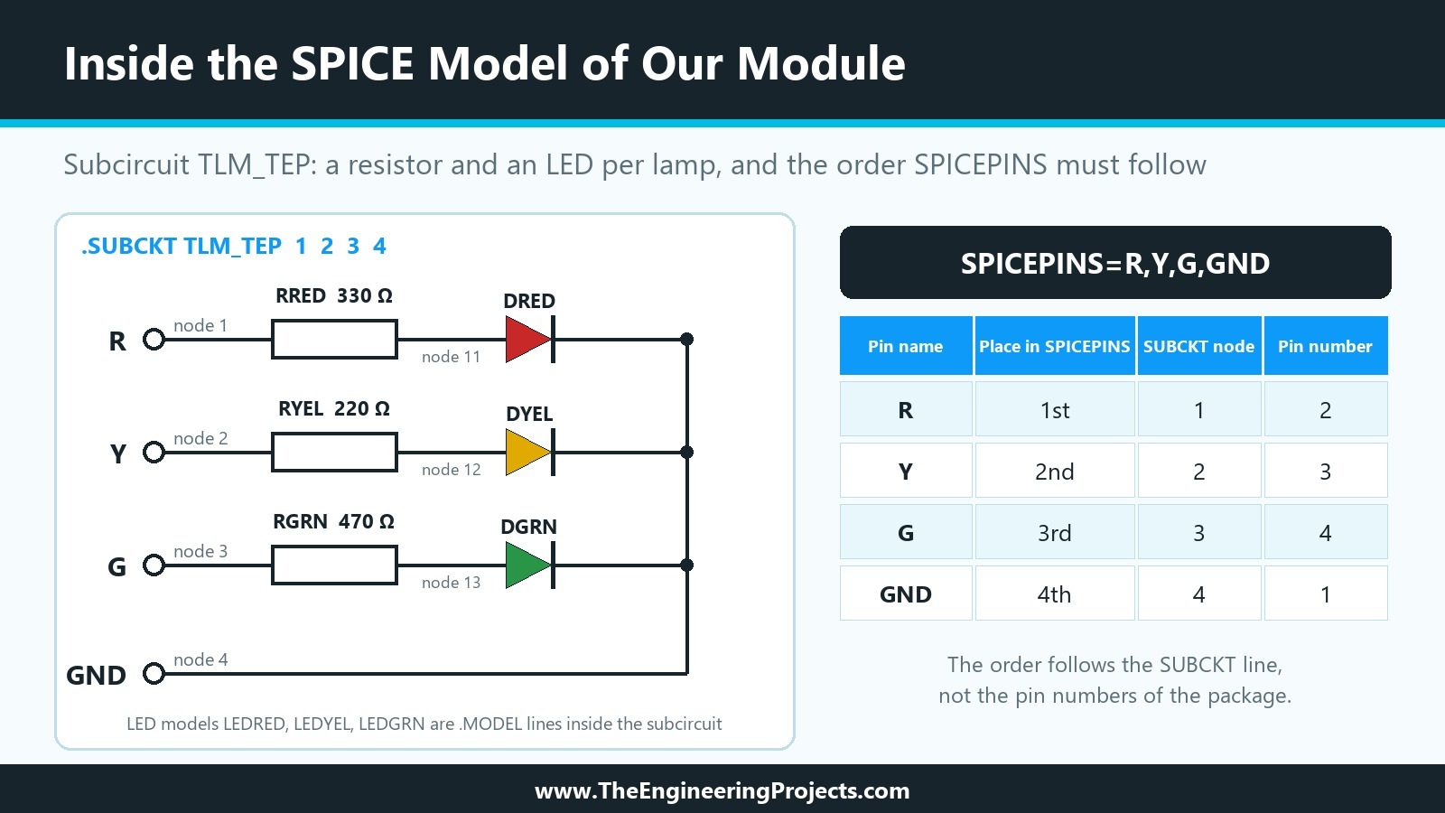
This property needs the most care. In SPICE, a subcircuit's connections are numbers, and they are matched by position: the first node on the .SUBCKT line is connection one, the second is connection two, and so on. The help explains why Proteus cannot simply use the pin numbers: a real package may have pins that the model ignores, and the model's node numbers are rarely in the order of the package pins. SPICEPINS solves this by listing the part's pin names in the order of the subcircuit's nodes.
Our module shows the trap clearly. GND is pin number 1 on the real header, but in our subcircuit it is the fourth node. So SPICEPINS is R,Y,G,GND, not GND,R,Y,G. The help adds two details: pin names may contain spaces, but there must be no space before a comma, and a pin name that itself contains a comma must be put in quotes.
How to Add a SPICE Model in Proteus: Step by Step
Adding the model took six steps: write the model file, open Make Device on the placed part, add the four properties, store the part, copy the model file into the Models folder, and test the result in a circuit.
Step 1: Write the SPICE Model File
Here is our complete model file, TRAFFICLIGHT.CIR. Lines that begin with an asterisk are comments. We copied the style of the comment block from the model files that manufacturers publish, where a small diagram above the .SUBCKT line shows which node is which connection. Write such a diagram into your own files; it is exactly the information you need for SPICEPINS.
* Traffic Light Module (TEP) - SPICE model for the Proteus library tutorial series
* The Engineering Projects, 2026
*
* Each channel is a series resistor and an LED to the GND pin, like the real board.
* Resistors: red 330 ohm, yellow 220 ohm, green 470 ohm.
* LEDs: simple diode fits, about 1.96 V (red), 2.07 V (yellow) and 2.16 V (green)
* at 10 mA. They are teaching values, not manufacturer models.
*
* connections:   R (red input)
*                |   Y (yellow input)
*                |   |   G (green input)
*                |   |   |   GND
*                |   |   |   |
.SUBCKT TLM_TEP  1   2   3   4
RRED  1 11 330
DRED 11  4 LEDRED
RYEL  2 12 220
DYEL 12  4 LEDYEL
RGRN  3 13 470
DGRN 13  4 LEDGRN
.MODEL LEDRED D(IS=4E-13 N=3 RS=10)
.MODEL LEDYEL D(IS=1E-13 N=3 RS=10)
.MODEL LEDGRN D(IS=3E-14 N=3 RS=10)
.ENDS TLM_TEP
The subcircuit has three branches. RRED connects node 1, the R pin, to an inner node 11, and the diode DRED connects node 11 to node 4, the GND pin. The yellow and green branches follow the same pattern with nodes 2, 12 and 3, 13. The three .MODEL lines inside the subcircuit describe the LEDs.
The Resistor Values
In the second tutorial, we noted that one published description of the module gives about 330 ohm for red, 220 ohm for yellow and 470 ohm for green, and that boards from other makers may use other values. The model uses exactly these values. If your board differs, change the three numbers; nothing else in the model or the part depends on them.
The LED Models
An LED is a diode, so each lamp uses a SPICE diode model with three parameters: the saturation current IS, the emission coefficient N and the series resistance RS. The forward voltage of such a diode is N times the thermal voltage, about 25.9 mV at SPICE's default temperature of 27 degrees Celsius, times the natural logarithm of the current divided by IS, plus the current times RS. With N=3 and RS=10 ohm, the three values of IS give forward voltages of about 1.96 V for red, 2.07 V for yellow and 2.16 V for green at 10 mA, typical figures for small indicator LEDs.
These are teaching values that we fitted ourselves, not models from an LED manufacturer, and the comment in the file says so. For a part that only has to load a microcontroller pin realistically, they are good enough. If you need a specific LED, put its published model in place of our .MODEL lines.
Why GND Is Node 4 and Not Node 0
In SPICE, node 0 is always ground, even inside a subcircuit. It would have been easy to connect the LEDs to node 0 and leave GND out of the subcircuit. We did not, because then the LEDs would light in the simulation even with the GND pin unconnected, while the real module would stay dark. With GND as a proper node, the model only works when the GND pin is wired, like the real board.
Step 2: Open Make Device on the Placed Part
As in the tutorial on component properties, we right-clicked our placed part U1 and chose Make Device. The first two pages, Device Properties and Packagings, stay as they are; Next brings us to Component Properties and Definitions, where LOGIC, VERSION and PACKAGE are already listed.
Step 3: Add PRIMITIVE, SPICEMODEL, SPICEFILE and SPICEPINS
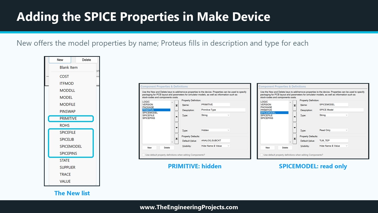
A click on New opens a list of property names that Proteus knows, and the four we need are all in it: PRIMITIVE, SPICEFILE, SPICELIB, SPICEMODEL and SPICEPINS sit next to MODFILE and MODDLL, the properties of the other model kinds. For each one, we picked the name from the list and typed its value into the Default Value field: ANALOG,SUBCKT, TLM_TEP, TRAFFICLIGHT.CIR and R,Y,G,GND.
Hidden or Read Only?
When we picked a name from the list, Proteus filled in the description and the type by itself: PRIMITIVE and SPICEPINS became Hidden, SPICEMODEL and SPICEFILE Read Only, all four with the visibility Hide Name and Value. These are exactly the definitions of Labcenter's own SPICE parts; the AD8014 amplifier in the ANALOGD library, for example, carries the same types. We kept them. Users of the part can see which model and file it uses, but they cannot change them by accident, and the pin list stays out of their way.
Raise the Version
A new model changes how the part behaves, so we also raised the VERSION property from 1.1 to 1.2, as planned in the tutorial on editing and updating parts. Anyone who opens a design can now tell whether a placed part already has the SPICE model.
Step 4: Store the Part and Update the Design
On the last page, TEPTUTORIAL was already selected as the library. Proteus asked whether to replace the existing TRAFFICLIGHTTEP, and we answered Yes; then it asked whether to update all instances of the device on the schematic, and we confirmed with OK. TEPTUTORIAL.LIB grew from 26,308 to 31,042 bytes, as each store adds a new version of the part to the file. These are the property lines that Make Device stored, read directly from the library file:
; TRAFFICLIGHTTEP version 1.2, read from TEPTUTORIAL.LIB after Make Device
{*PROPDEFS}
{LOGIC="Lamps light when the pin is",HILOW}
{VERSION="Library version",READONLY STRING}
{PACKAGE="PCB Package",PACKAGE,1,TRAFFICLIGHT-TEP}
{PRIMITIVE="Primitive Type",HIDDEN STRING}
{SPICEMODEL="SPICE Model",READONLY STRING}
{SPICEFILE="SPICE Model File",READONLY STRING}
{SPICEPINS="SPICE SUBCKT Pin List",HIDDEN STRING}
{*COMPONENT}
{LOGIC=1}
{VERSION=1.2}
{PACKAGE=TRAFFICLIGHT-TEP}
{PRIMITIVE=ANALOG,SUBCKT}
{SPICEMODEL=TLM_TEP}
{SPICEFILE=TRAFFICLIGHT.CIR}
{SPICEPINS=R,Y,G,GND}
Two things are worth noticing. LOGIC is stored as 1, the internal value of High. And the new properties sit in the same {*PROPDEFS} and {*COMPONENT} sections as the properties we added by hand in the eighth tutorial; a model is attached with nothing more than properties.
Step 5: Copy the Model File into the Models Folder
The part now knows the name of its model file, but the file itself must be where PROSPICE looks for it. We copied TRAFFICLIGHT.CIR into the MODELS folder of the Proteus 8.5 installation, next to the supplied .SML libraries. To check the folder on your own PC, open System Settings and look at Simulation Model and Module Folders on the Simulator Settings tab. On many PCs, writing into the Program Files folder needs administrator rights; on ours, the MODELS folder was writable for all users.
In fact, we did this step last and pressed Run first, to see what happens when the file is missing. You will find the result in the section on errors below.
Step 6: Build a Test Circuit and Run It
To see the model at work, we need something that measures it. We used the DC ammeter from the Virtual Instruments mode, one per lamp.
The Test Circuit
Each ammeter sits between a power terminal labelled +5V and one of the pins R, Y and G, with its plus side towards the supply, so that the current into the module reads positive. We named the ammeters RED, YELLOW and GREEN and set their Display Range to Milliamps. The GND pin goes to a ground terminal. Proteus reads the voltage from the label of a power terminal, so +5V is all it takes to get a 5 V supply.
The Results
After Run, the simulation started without any error, and the ammeters showed 9.26 mA for red, 13.1 mA for yellow and 6.20 mA for green. These are the values the model predicts. For the red lamp, the LED takes about 1.94 V at that current, and the remaining 3.06 V across 330 ohm give 9.26 mA. The yellow lamp draws the most current because it has the smallest resistor, and the green lamp the least.
With the simulation paused, a right-click on U1 offers Operating Point Info. For our part, it showed the voltages at its terminals: 5.000 V on R, Y and G and 0.00 V on GND. The nodes inside the subcircuit are not listed there; the ammeters are the better tool for a part like ours.
What the SPICE Model Shows and What It Does Not
A model is only useful if it behaves like the real part when the circuit changes, and if we know where its limits are.
Testing at 3.3 V
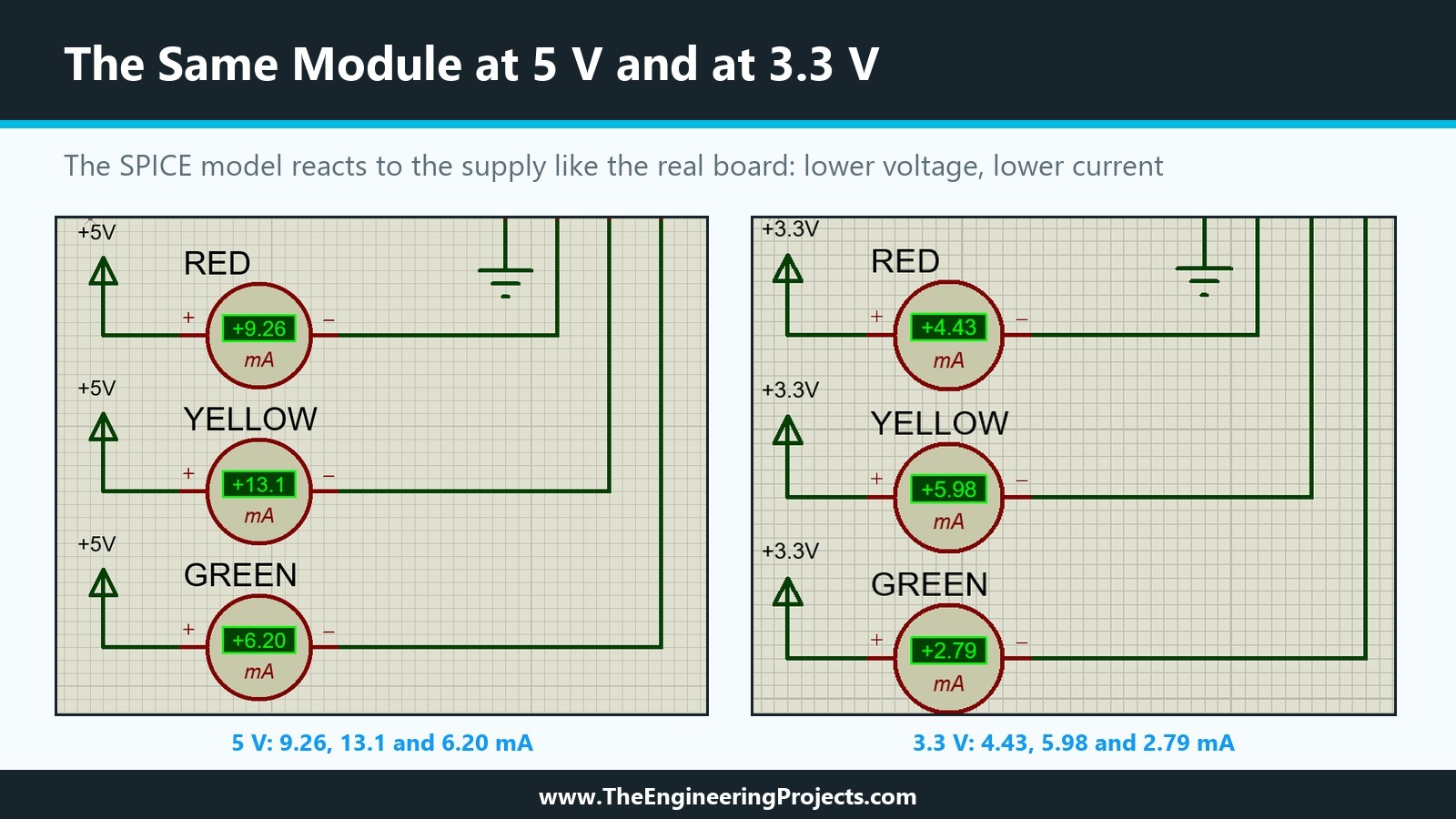
Many boards today, such as the ESP32 or the Raspberry Pi Pico, drive their pins at 3.3 V. We changed the three terminal labels to +3.3V and ran the simulation again. The currents dropped to 4.43 mA for red, 5.98 mA for yellow and 2.79 mA for green, again exactly what the model predicts. On a real module, the lamps would be noticeably dimmer at 3.3 V, and the green one the dimmest, and the simulation now shows that in numbers.
The Lamps Stay Dark
During both tests, the three lamps of our part stayed in their dark off colours. That is expected. A SPICE model only calculates voltages and currents; it has no way to change the drawing of the part. The LOGIC property is not used by the model either: our subcircuit describes the real board, where a high pin lights a lamp, and nothing in it reads LOGIC. Lighting the lamps is a job for the animation tutorials later in the series.
SPICE Model Errors and How to Read Them
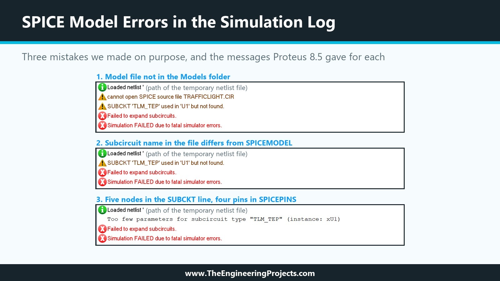
To learn the messages, we made three mistakes on purpose and pressed Run each time. Every time, Proteus showed a box with Fatal simulation error(s) encountered! and, after OK, opened the Simulation Log with the details.
Cannot Open SPICE Source File
Our first run happened before the model file was in the Models folder. The log said "cannot open SPICE source file TRAFFICLIGHT.CIR", followed by "SUBCKT 'TLM_TEP' used in 'U1' but not found.", "Failed to expand subcircuits." and "Simulation FAILED due to fatal simulator errors.". The first line is the important one: it names the file Proteus looked for. Check the spelling of SPICEFILE and the folder.
SUBCKT Used but Not Found
For the second test, we changed the name on the .SUBCKT line in the copied file to TLM_TEP1, as if we had made a typing mistake. The file was found this time, so the first message disappeared, but "SUBCKT 'TLM_TEP' used in 'U1' but not found." remained. This message alone means that the file opened but the name in SPICEMODEL does not match any .SUBCKT line in it.
Too Few Parameters for Subcircuit
For the third test, we added a fifth node to the .SUBCKT line, so that the subcircuit expected five connections while SPICEPINS listed four. The log said "Too few parameters for subcircuit type "TLM_TEP" (instance: xU1)". The xU1 is the SPICE name of our part in the netlist: an X line calls a subcircuit, followed by the reference. Whenever you see this message, count the nodes on the .SUBCKT line and the names in SPICEPINS.
A model can also load without errors and still behave wrongly, for example when two names in SPICEPINS are swapped. No message warns about that, which is why a test with meters, as in Step 6, belongs to every new model. For models from manufacturers, the help gives two more hints: a model written for PSpice may use syntax that PROSPICE does not accept, so check that it was written for SPICE 2 or SPICE 3, and a simulation that does not converge can be made more stable by raising GMIN from its default of 1E-14 to 1E-13 or 1E-12.
Other Ways to Supply a SPICE Model
SPICEFILE with a plain text file is not the only route. Here are the others, one of which we tested.
A SPICE Model Library (.SML) with SPICELIB
Labcenter keeps its own models in binary SPICE model libraries, the .SML files of the Models folder. The help gives two reasons: many tiny model files waste disk space, and when one text file holds many models, PROSPICE has to read the whole file to find one. Proteus 8.5 includes two command line tools for these libraries in its BIN folder: PUTSPICE puts models into a library, and GETSPICE gets them out again.
Our first attempts failed with a box saying "Cannot open library", even when we only tried to read one of Labcenter's own libraries. The cause was the folder: our working folder had a path of 133 characters, and these old tools could not handle it. From the same folder addressed by its short 8.3 path, both tools worked at once:
PUTSPICE -L=TEPTUTORIAL.SML -C TRAFFICLIGHT.CIR
PUTSPICE - Put SPICE model files into library.
Processing TRAFFICLIGHT.CIR.
Storing TLM_TEP

GETSPICE -L=TEPTUTORIAL.SML TLM_TEP
GETSPICE - Get SPICE model files from library.
Created SPICE file TEPTUTORIAL.MOD
Writing TLM_TEP.
The -C switch creates the library. PUTSPICE stores each subcircuit under its own name, TLM_TEP, and the extracted file showed that it keeps only the subcircuit itself, from .SUBCKT to .ENDS; the comment lines outside it are not stored. Our library file has 321 bytes.
Testing SPICELIB on One Placed Part
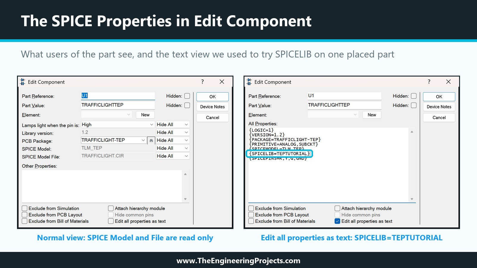
To try the library without changing our library part, we copied TEPTUTORIAL.SML into the Models folder, renamed TRAFFICLIGHT.CIR there for the test so that Proteus could not use it, and edited U1 alone. In the Edit Component dialogue, the box Edit all properties as text shows every property of the placed part as text, the hidden and read-only ones included. We replaced the SPICEFILE line with {SPICELIB=TEPTUTORIAL}. The simulation gave the same 4.43, 5.98 and 2.79 mA at 3.3 V, so the model now came from the .SML library. Afterwards, we restored SPICEFILE on U1 and the file name in the Models folder.
For a model that you are still changing, the plain file is more practical. A library pays off when you have many models or want to ship them as one file, a question we return to in the last tutorial of the series.
A MODEL Card for a Diode or Transistor
For diodes, transistors, JFETs and MOSFETs, a manufacturer's model is usually one .MODEL line. The help explains that this case is simpler, because there is no pin order to translate: the generic parts in the ASIMMDLS library already have the right PRIMITIVE, such as ANALOGUE,NPN for an NPN transistor, and you only add SPICEMODEL with the model name and the file. The help's example is a 2N2222 with SPICEMODEL=Q2N2222,SPICEMOD.LIB, the name and the file in one property. In ASIMMDLS on our PC, several generic parts also define SPICEFILE as a file-name property for .INC and .LIB files, ready for such a model file.
A SPICE Model in a Script on the Schematic
Finally, the help describes typing a model straight onto the schematic in a script block that starts with *SCRIPT SPICE and ends with *ENDSCRIPT. The part's SPICEMODEL then gives only the model name, without a file. The help suggests this for models obtained on paper or for trying parameter values interactively. It keeps the model inside one design, though, so it is not a way to build a library part.
Common Mistakes When Adding a SPICE Model in Proteus
| Problem | Cause | Solution |
|---|---|---|
| cannot open SPICE source file | The file is not in a model folder, or SPICEFILE is misspelt | Copy the file to the Models folder and check the name and extension |
| SUBCKT used but not found | SPICEMODEL does not match the .SUBCKT line | Copy the name from the file, including suffixes such as /NS |
| Too few parameters for subcircuit | The node count and the SPICEPINS count differ | Count the nodes and the pin names |
| Wrong currents, no error | Pin names in SPICEPINS are in the wrong order | Follow the node diagram in the model's comments |
| Simulation breaks on PRIMITIVE | A space after the comma | Write ANALOG,SUBCKT without spaces |
| The part works without its GND pin | The model uses node 0 instead of a GND node | Give GND its own node in the subcircuit |
| Cannot open library from PUTSPICE or GETSPICE | A long working folder path | Run the tools from a short path |
In the Next Tutorial
Our part now has a working SPICE model with realistic currents, but its lamps still stay dark. In the next tutorial, How to Create a Schematic Simulation Model (MDF) in Proteus, we build a model from a drawn circuit instead of text, compile it into a model file and see what a schematic model can do for our module that a SPICE subcircuit cannot.
FAQ
How do I add a SPICE model to a part in Proteus?
Open Make Device on the part, add PRIMITIVE=ANALOG,SUBCKT, SPICEMODEL with the subcircuit name, SPICEFILE with the model file (or SPICELIB with an .SML library) and SPICEPINS with the pin names in node order, store the part, and copy the model file into the Models folder.
What is SPICEPINS in Proteus?
A property that lists the part's pin names in the order of the nodes on the .SUBCKT line, so that each pin connects to the right node of the model. The order has nothing to do with the pin numbers.
Where should I put a SPICE model file for Proteus?
In one of the folders listed under Simulation Model and Module Folders in System Settings, normally the Models folder of the installation. According to the help, the current directory is also searched.
Can I use a PSpice model in Proteus?
Often, but not always. PROSPICE is based on SPICE3F5, and models written for PSpice may use syntax it does not accept. If a model fails, check that it was written for SPICE 2 or SPICE 3.
Does a SPICE model animate a Proteus part?
No. A SPICE model only calculates voltages and currents. Lamps, LEDs and displays that change on the screen need a schematic model or a VSM DLL with animation states.
What are PUTSPICE and GETSPICE?
Command line tools in the BIN folder of Proteus that put models into a SPICE model library (.SML) and get them out again. In our test, they worked only when started from a folder with a short path.
That is all for today. Our Traffic Light Module now simulates like the real board, at least electrically. If you have any questions, ask in the comments. Take care.