Hello friends, I hope you all are doing great. Today, I am going to share our new Joystick Module Library for Proteus. The KY-023 is the small black thumb joystick module, the same kind of stick you find on a game controller: two 10 k potentiometers measure where the stick is, and a push switch sits under it. With this Joystick Module Library for Proteus, you click or drag the stick in Proteus, and your Arduino reads it with analogRead() and digitalRead(), exactly as it reads a real board.
This is version 1.0, the first joystick library from our team. You get two devices: Joystick Simple, with a big control panel on the schematic, and Joystick Advance, with a pop-up window and four measured joystick test tools. The model behaves like a real cheap stick: it does not rest at exactly 512, it springs back to the centre, and its button bounces. The Joystick Arduino Proteus demo runs on two Arduino UNOs and prints the direction ("UP", "DOWN-LEFT", "CENTER" ...) in the compact Simple interface of our TEP Serial Monitor.
NOTICE: This library is very special to our team. Our joystick model is a real analog part in Proteus's simulator: two pot dividers with the drift, the spring and the round gate of a real stick, and a push switch that bounces like a real tact switch. It took our team a lot of hard work, many test runs and many design changes. Your feedback is the fuel that keeps us going, so please tell us what you think in the comments below or in the Joystick Module Library board of our forum. And if our free libraries help you, you can buy us a coffee. So, let's get started with the Joystick Module Library for Proteus:
What is a Joystick Module (KY-023)?
A joystick module is a small board with a thumb stick on a gimbal. The stick turns two potentiometers (pots), one for each axis, set at 90 degrees to each other. Each pot is a voltage divider between +5V and GND, so its middle pin, the wiper, gives a voltage that follows the stick: about half the supply at rest, the full supply at one end and 0 V at the other. When you press the stick down, a small tact switch under it connects the SW pin to GND.
The common board is called KY-023, or the "PS2 joystick module". Makers use it to steer robots and RC cars, to move a cursor or a game character, or as a five-way menu button.
The KY-023 at a Glance
| Feature | Value |
|---|---|
| Outputs | VRx and VRy: two analog voltages; SW: a switch to GND |
| Potentiometers | Two 10 k pots, one per axis |
| At rest | About half the supply on both axes; a real stick reads a few counts off 512 |
| Push switch | A tact switch under the stick; SW is shorted to GND while you press |
| Pull-up on SW | None on the board: the sketch uses the Arduino's internal pull-up |
| Pins | GND, +5V, VRx, VRy, SW (a 5-pin header) |
| Supply | 3.3 to 5 V; VRx and VRy follow the supply (ratiometric) |
| Board | About 34 x 26 mm, black, with the header on a short edge |
From Stick Position to ADC Count
The Arduino UNO measures 0 to 5 V with its 10-bit ADC (analog-to-digital converter) and gives a number from 0 to 1023, the count: count = 1024 x V / 5 V. A stick exactly in the middle (2.5 V) reads 512. In our Proteus run, VRx at rest was 2.541 V: 1024 x 2.541 / 5 = 520.4, and the sketch read 520. The UNO in Proteus rounds to the nearest count; a real UNO truncates, so it may read one count lower.
Two things surprise most people. First, a real stick never comes back to exactly 512: ours rests at 520 / 506, with a count or two of jitter. Second, the pots reach 0 and 1023 before the end of the travel, at about 71 %, and on a diagonal each axis gets only about 0.7 of the push (a round gate).
Joystick Terms You Will See in This Article
| Term | Meaning |
|---|---|
| VRx, VRy | The two pot outputs: VRx for up / down, VRy for left / right (as the module is held here) |
| SW | The push switch under the stick: LOW while pressed |
| Count | The ADC result of analogRead(), 0 to 1023 |
| Rest value / drift | Where a released stick really sits (520 / 506 here), with a count or two of jitter |
| CENTER zone / dead zone | The counts your sketch treats as "not pushed"; the demo uses 300 to 700 |
| Travel | How far the stick is pushed, from -100 % to +100 % |
| Round gate | The round opening that limits the stick: a diagonal push is about 0.7 of the travel on each axis |
| Bounce | A switch contact closing and opening a few times in the first milliseconds of a press |
| Debounce | Ignoring those quick edges: count a press only after the level stays (the demo waits 50 ms) |
| INPUT_PULLUP | The Arduino's internal pull-up resistor, so SW reads HIGH when the button is free |
Features of the Joystick Module Library for Proteus
Here is what you get in version 1.0:
- Two devices in
TEPJOYSTICK.LIB: Joystick Simple (JOYSTICKTEP) and Joystick Advance (JOYSTICKADVTEP), one model,TEPJOYSTICK.DLL. - A real analog part: VRx and VRy are pot dividers in Proteus's SPICE simulator and SW is a contact to GND, so analogRead, digitalRead and attachInterrupt work as on a real board.
- Real stick behaviour: rails at about 71 % of the travel, rest values 520 / 506 with jitter, a 60 ms move, a spring return in about 0.15 s and a round gate.
- Contact bounce: 0.4 to 2.6 ms at every press, so your sketch has to debounce (BOUNCE OFF removes it).
- An animated board: a moving thumb cap, an X-Y screen and PWR / SW LEDs.
- The panels show what your sketch reads: the same rounded ADC counts and the same direction word as the demo sketch.
- An event log, a 10 s chart and four measured test tools on the Advance.
- A two-UNO demo with the TEP Serial Monitor: the direction word, a debounced press counter, INT0 edge counting and commands.
- A small package: about 1.42 MB, without the C++ source code.
Joystick Module Library for Proteus: Simple vs Advance
Both devices run the same model with the same properties; only the panel differs:
| Feature | Simple | Advance |
|---|---|---|
| Full joystick model (two pots, the switch with its bounce, the spring, the drift, the round gate) | ✔ | ✔ |
| Black KY-023 board: moving thumb cap, X-Y screen, PWR / SW LEDs | ✔ | ✔ |
| JOYSTICK SCENE panel on the schematic: big top view, X-Y plot, mini game, D-pad, PRESS / HOLD, SPRING, DRIFT | ✔ | ✘ |
| Pop-up window you can move, resize and minimise | ✘ | ✔ |
| Stick page: push sliders, rest values, BOUNCE switch, live 10 s chart, event log | ✘ | ✔ |
| Axis sweep, Centre return, SW press timing and D-pad map | ✘ | ✔ |
| TEP Dark / Light theme, text size, Help page with Copy diagnostics | ✘ | ✔ |
| Close the panel and open it again (red X and PANEL / OPEN PANEL) | ✔ | ✔ |
Choose Simple to keep the stick and the controls beside your circuit, and Advance when your sheet is full or you want hard numbers: the real centre, the dead zone and the bounce. The demo has one of each.
Download Joystick Module Library for Proteus
Click the button below to download Joystick-Module-Library-for-Proteus-v1.0.zip (about 1.42 MB, without the C++ source code):
Joystick Module Library for Proteus V1.0- README.txt: a detailed guide to the files, the wiring, the model, the test tools and real hardware.
- Proteus Library Files:
TEPJOYSTICK.LIB(both devices),TEPSERIALMON.LIBand our Arduino UNO libraryArduinoV3TEP.LIB/ArduinoV3TEP.IDX. - Proteus Model Files:
TEPJOYSTICK.DLLandTEPSERIALMON.DLL. - Proteus Simulation:
Joystick-Module-ArduinoUnoV3.pdsprj,Joystick_Direction_Demo.hex(both UNOs run it) and copies of both DLLs. - Arduino Code:
Joystick_Direction_Demo.ino, the source of the HEX file. It needs no extra Arduino library.
No Proteus yet? Read How to Download and Install Proteus 7 and 8. New to libraries? Follow How to Install a New Library in Proteus.
How to Install Joystick Module Library for Proteus
- Close Proteus and extract the whole zip file to a normal folder, for example your Desktop.
- Copy the four files from Proteus Library Files into the LIBRARY folder, usually
C:\Program Files (x86)\Labcenter Electronics\Proteus 8 Professional\LIBRARY(on some PCsC:\ProgramData\Labcenter Electronics\Proteus 8 Professional\LIBRARY; use the folder that already holds Proteus's own .LIB files). - Copy
TEPJOYSTICK.DLLandTEPSERIALMON.DLLinto the MODELS folder. - If a
TEPJOYSTICK.IDXfile is in the LIBRARY folder, delete it. - Start Proteus, press P and search for JOYSTICK. You get the Simple and the Advance device, in the category Sensors > Joysticks.
Tip: keep Joystick_Direction_Demo.hex and the two DLLs beside the demo project when you copy it somewhere else. The library was tested in Proteus 8.5; Proteus 7 is not supported.
The Joystick Module in Proteus
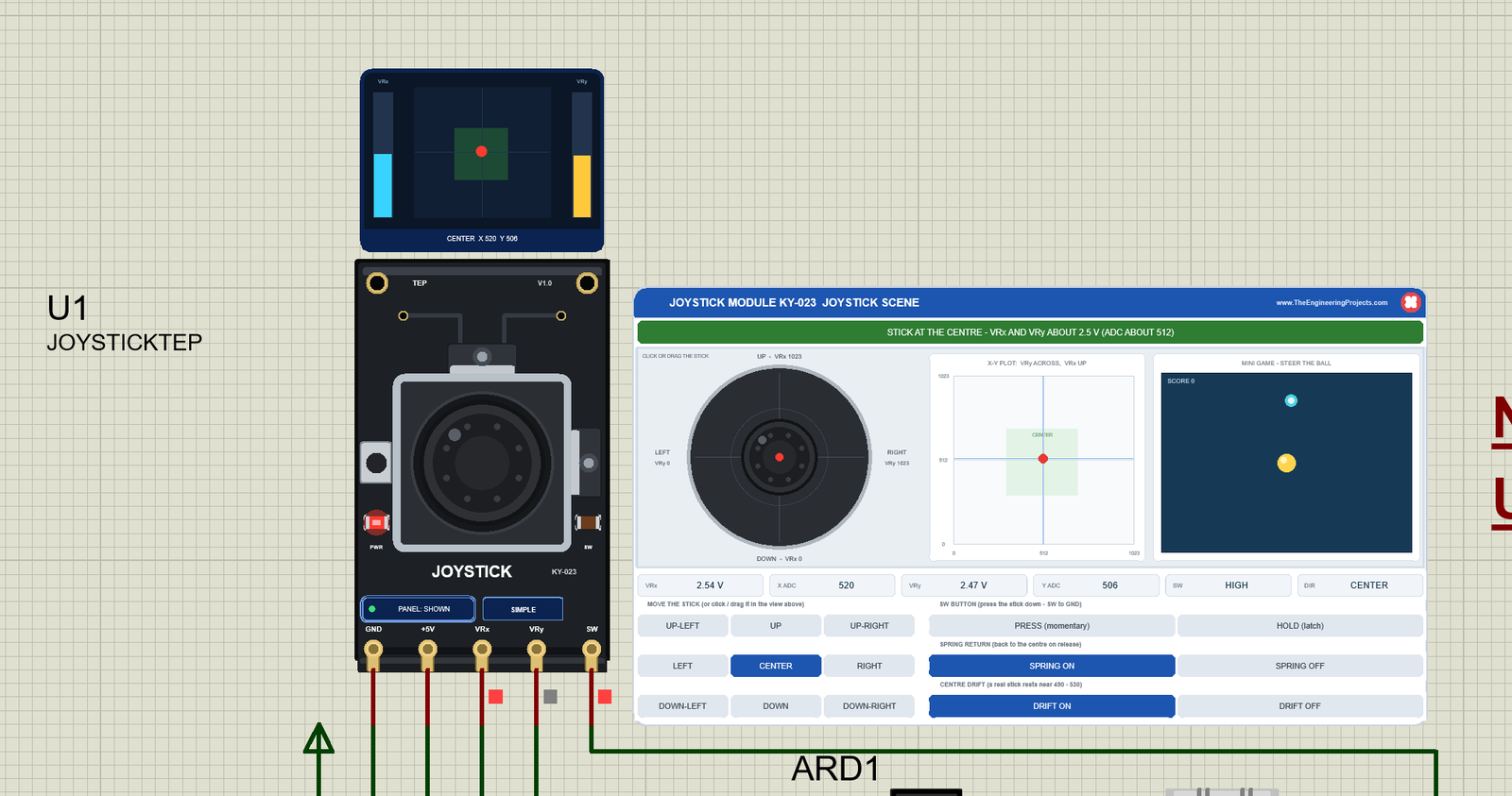
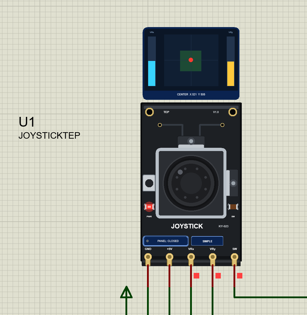
We drew the KY-023 as a clean TEP board in the real module's black colour and shape: the board stands upright, with the 5-pin header on its bottom edge, four gold mounting holes, the silver gimbal housing with the round thumb cap, the two pots beside the housing and the "JOYSTICK KY-023" print. Here is U1, the Simple device, at rest:
The Thumb Cap
The cap on the board moves with the stick, and you can drag it right there on the board. When you press the stick, the cap sinks and gets an orange ring (see HOLD below).
The X-Y Screen
Above the board sits a small screen: the VRx bar (blue) on the left, the VRy bar (amber) on the right, and in the middle the stick as a red dot with a short trail over the green CENTER zone of the demo sketch. The bottom line gives the word and both counts: CENTER X 520 Y 506. The screen is a TEP addition.
Pinout
The pins are in the order of the KY-023 header:
| Pin | What it does | Demo connection |
|---|---|---|
| GND | Ground | GND |
| +5V | Supply of both pots (3.3 to 5 V on a real board) | Power terminal |
| VRx | Up / down pot: 0 V DOWN, about 2.5 V at rest, 5 V UP | Arduino A1 |
| VRy | Left / right pot: 0 V LEFT, 5 V RIGHT | Arduino A0 |
| SW | Push switch to GND, active low; no pull-up on the board | Arduino D2 (INT0), with INPUT_PULLUP |
Which Way Is Up?
With the pins pointing down, as the symbol is drawn, a push UP takes VRx to 1023 and a push RIGHT takes VRy to 1023. Many tutorials hold the module with the pins to the left; then VRx is left / right. Which axis is "X" only depends on how you hold the board.
LEDs and Indicators
| Indicator | What it shows |
|---|---|
| Thumb cap | Moves with the stick; sinks with an orange ring while the stick is pressed |
| PWR LED (red) | Lit while the board has power |
| SW LED (orange) | Lit while the switch is pressed |
| X-Y screen | VRx / VRy bars, the CENTER zone, the stick as a dot with a trail, the word and both counts |
| PANEL / OPEN PANEL, SIMPLE / ADVANCE | The panel button and the device badge |
The real KY-023 has no LED at all: the PWR and SW LEDs, the X-Y screen and the panel button are TEP additions. The small squares under the pins are Proteus's own logic-state markers (red high, blue low, grey in between).
Component Properties
| Property | Meaning | Default |
|---|---|---|
| SPRING | Spring return to the centre on release, ON or OFF | ON |
| DRIFT | Centre drift and ADC noise like a real stick, ON or OFF | ON |
| XCENTRE | VRx rest value with DRIFT ON, ADC 400 to 624 | 520 |
| YCENTRE | VRy rest value with DRIFT ON, ADC 400 to 624 | 506 |
| POSITION | The stick at the start: CENTER, UP, DOWN, LEFT, RIGHT or a diagonal; it stays there until you move it | CENTER |
| BOUNCE | SW contact bounce like a real tact switch, ON or OFF | ON |
| PANEL | Simple only: the panel at the start, OPEN or CLOSED | OPEN |
Every Run starts again from these properties; the panel clicks last until the simulation stops. An extra property, REDRAW=FULL (Other Properties), redraws the whole part on every frame; use it only if Proteus ever leaves a stale picture.
Joystick Simple: The JOYSTICK SCENE Panel
Beside the Simple board sits the JOYSTICK MODULE KY-023 JOYSTICK SCENE panel (on the right of the image above). It is the joystick's playground:
| Part | What it does |
|---|---|
| Header, red X | The panel's name; the X closes the panel |
| Status banner | STICK AT THE CENTRE (green), STICK MOVED (blue) or BUTTON PRESSED (red), with a short explanation |
| Big top view | CLICK OR DRAG THE STICK: the cap seen from above; UP = VRx 1023, DOWN = VRx 0, LEFT = VRy 0, RIGHT = VRy 1023; SW PRESSED while the button is down |
| X-Y plot | VRy across, VRx up, from 0 to 1023, with the sketch's CENTER zone and a dot at the stick |
| Mini game | STEER THE BALL: the stick rolls the ball; steer it onto the coins for SCORE |
| Readouts | VRx (volts), X ADC, VRy (volts), Y ADC, SW (HIGH / LOW) and DIR (the demo's word) |
| D-pad | UP-LEFT, UP, UP-RIGHT, LEFT, CENTER, RIGHT, DOWN-LEFT, DOWN, DOWN-RIGHT: a full push that way |
| PRESS (momentary), HOLD (latch) | The SW button: pressed while you hold the mouse button, or latched until you click HOLD again |
| SPRING ON / OFF | Back to the centre on release, or the stick stays where you leave it |
| DRIFT ON / OFF | The real rest values 520 / 506 with jitter, or an ideal 512 / 512 stick |
In the start image, the banner says "STICK AT THE CENTRE - VRx AND VRy ABOUT 2.5 V (ADC ABOUT 512)", but the readouts show VRx 2.54 V = 520 and VRy 2.47 V = 506: the centre drift of a real stick ("a real stick rests near 490 - 530"). DRIFT OFF gives an ideal 512 / 512 stick. A D-pad button keeps the stick pushed while you hold the mouse button and 0.5 s after it; then the spring brings it back.
UP-RIGHT with the Spring Off
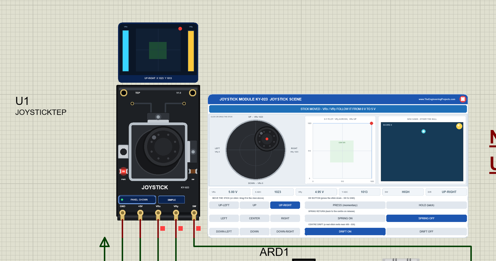
Click SPRING OFF, then UP-RIGHT. The cap moves to the upper right, in the big view and on the board, and the banner turns blue: "STICK MOVED - VRx / VRy FOLLOW IT FROM 0 V TO 5 V". VRx reads 5.00 V = 1023 and VRy 4.95 V = 1013. Why not 1023? On a diagonal each axis gets only about 0.7 of the push, and VRy starts lower (506), so it stops just short of the rail: the round gate. With the spring off, the stick stays here, and the mini game's ball has rolled into the top right corner.
HOLD: Pressing the Button
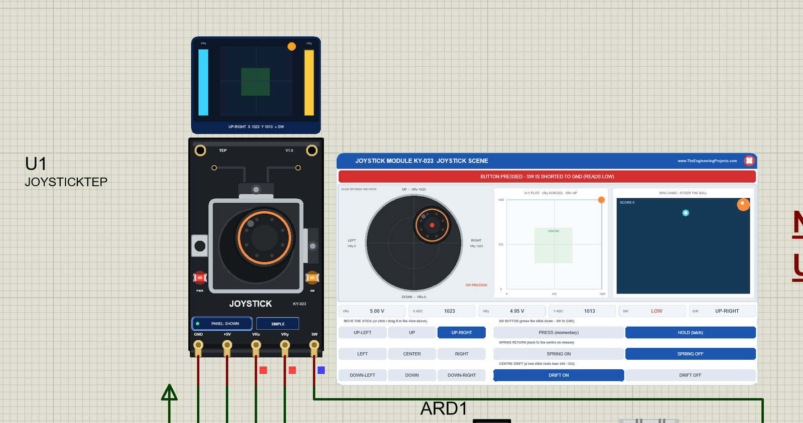
Now click HOLD (latch). The banner turns red: "BUTTON PRESSED - SW IS SHORTED TO GND (READS LOW)". The cap sinks and gets an orange ring, the orange SW LED lights, the big view says "SW PRESSED", the screen adds "+ SW", SW reads LOW, and Proteus's marker under the SW pin turns blue. The stick is still at UP-RIGHT: like a real thumb, you can push and press at once.
PRESS (momentary) keeps the switch closed only while you hold the mouse button; HOLD stays closed until you click it again. The demo's green LED on A3 and the UNO's LED on D13 light while the sketch sees the button pressed.
Closing the Panel
Click the red X in the panel's header: the board button says PANEL: CLOSED, and the joystick keeps running. PANEL on the board brings the panel back. Here, U1 is back at the centre:
Joystick Advance: The Pop-Up Window
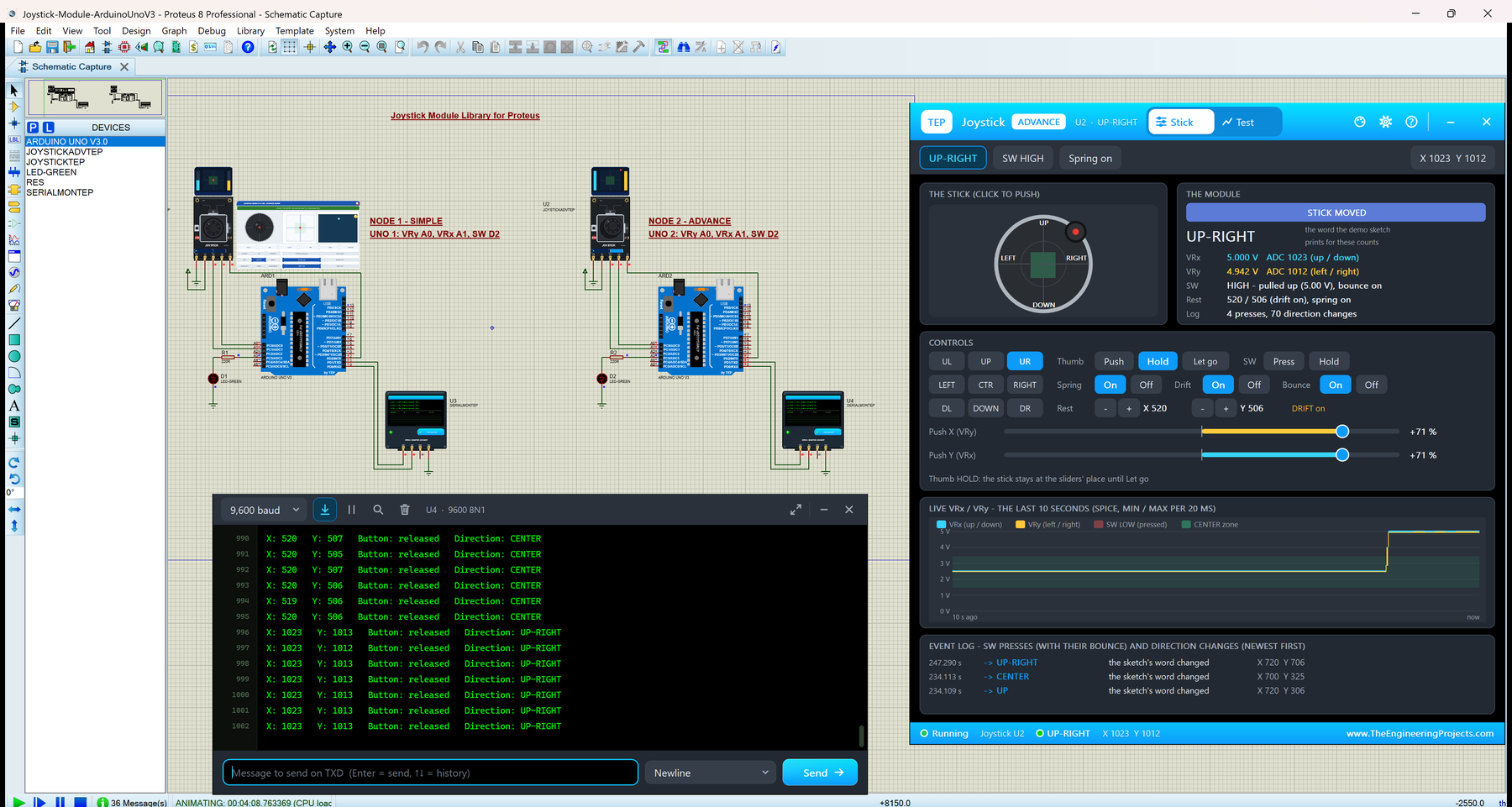
The Advance device keeps only the board on the schematic. Here is U2, at rest:
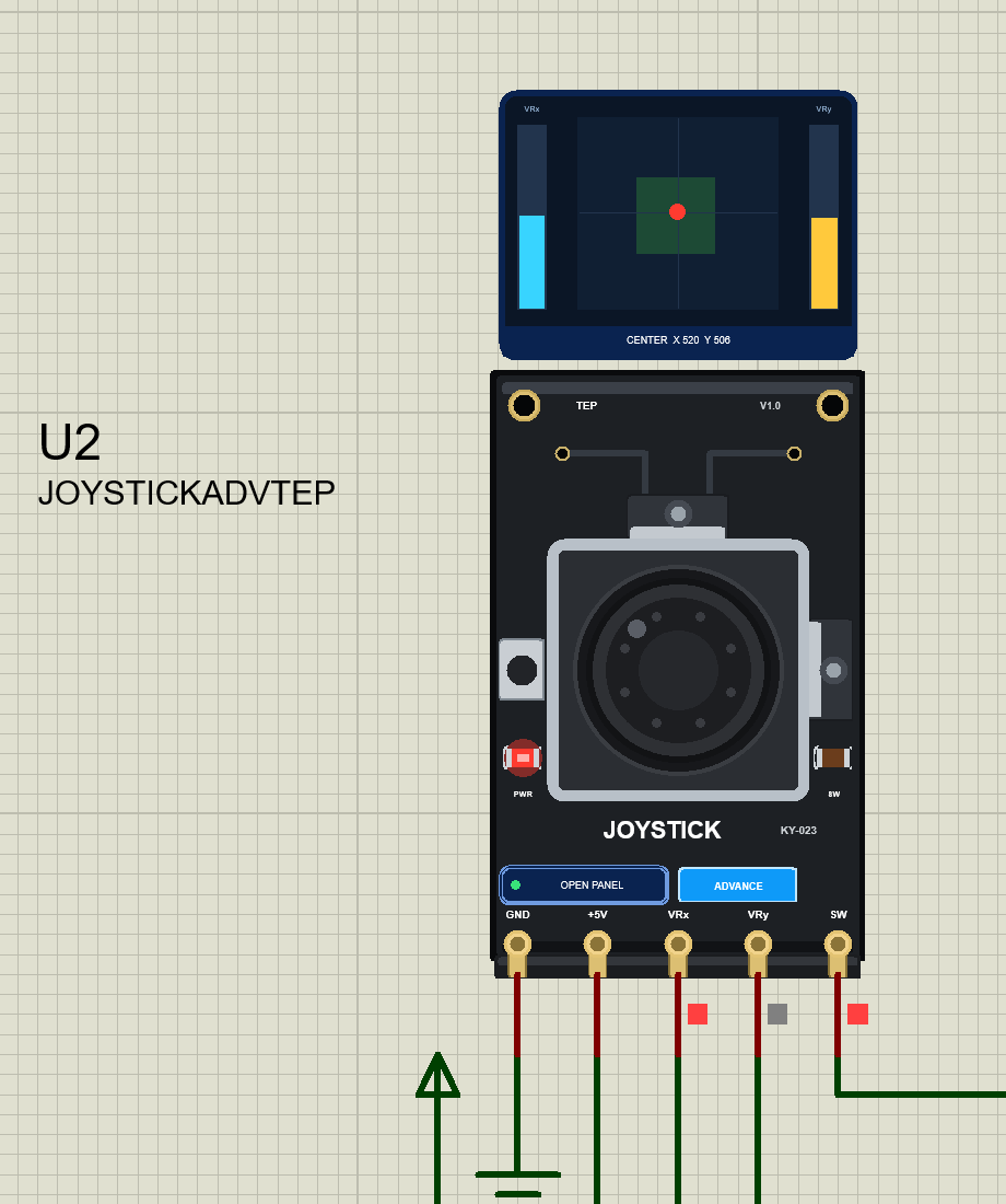
At Run, the "TEP Joystick Module Advance" pop-up opens, with the look of our TEP Serial Monitor and no Windows title bar: move it by its header, resize or minimise it, and reopen it with OPEN PANEL. The header shows the state (here U2 · UP-RIGHT), the Stick and Test tabs, and the palette (theme), gear (Settings) and ? (Help) icons; four chips below it repeat the word, SW, the spring and both counts.
The Stick Page
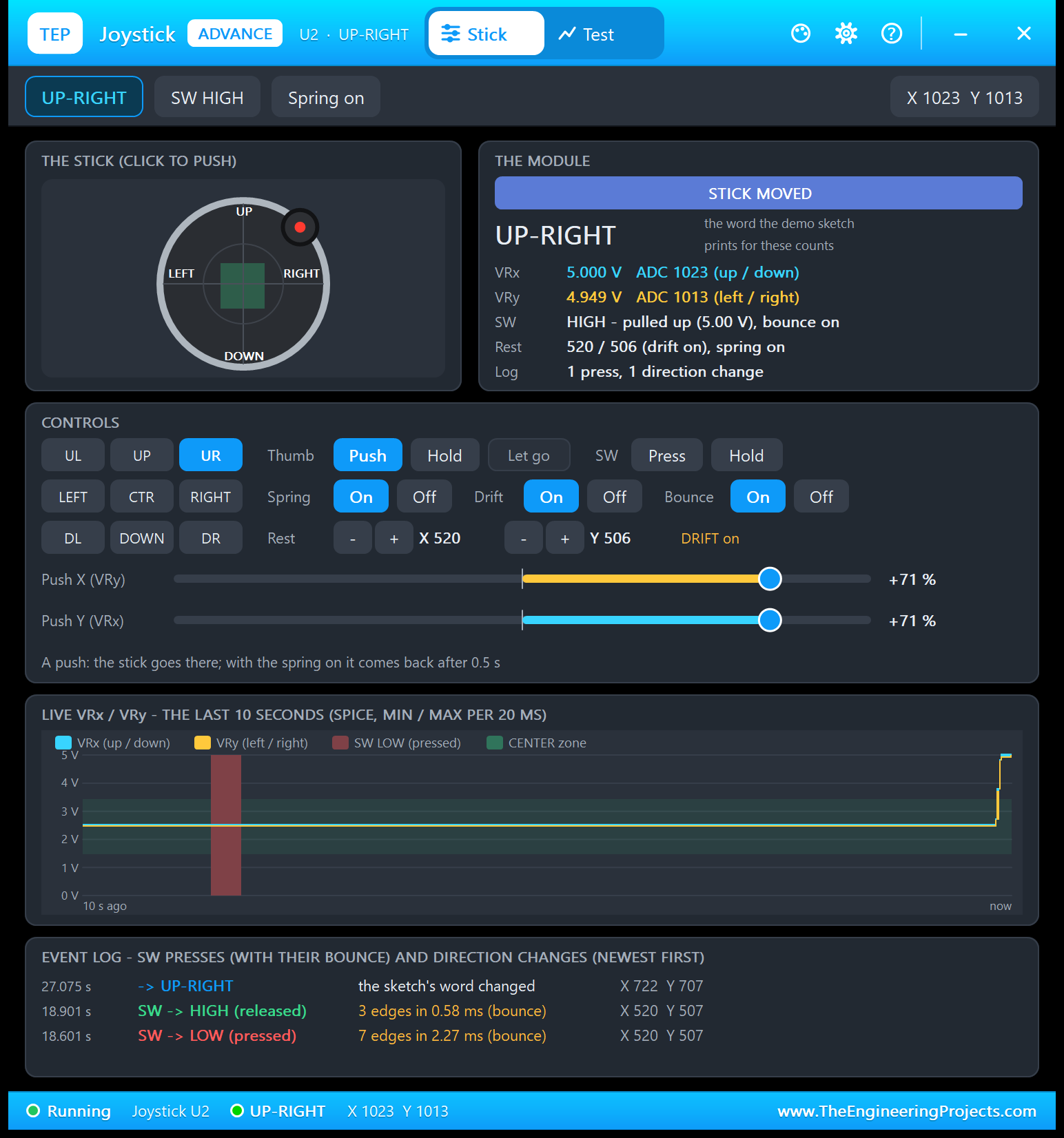
- THE STICK (CLICK TO PUSH): click anywhere in the ring to push the stick there. The green square is the sketch's CENTER zone where it really is (the drift shifts it a little).
- THE MODULE: the banner, the word the demo sketch prints for these counts (UP-RIGHT), VRx 5.000 V = ADC 1023, VRy 4.949 V = ADC 1013, "SW HIGH - pulled up (5.00 V), bounce on", the rest values and the log counts.
- CONTROLS: the D-pad (UL to DR), Thumb Push / Hold / Let go, SW Press / Hold, Spring, Drift and Bounce On / Off, the rest values with - / +, and two sliders, Push X (VRy) and Push Y (VRx), from -100 to +100 % of the travel.
- LIVE VRx / VRy - THE LAST 10 SECONDS: min / max per 20 ms, the CENTER zone as a band, red shading while SW is LOW.
- EVENT LOG: every press with its bounce and every change of the sketch's word, newest first.
Push X moves VRy and Push Y moves VRx: with the pins down, left / right is the X direction on the screen, but the VRy pot measures it. Here I clicked UR with the thumb on Push: "A push: the stick goes there; with the spring on it comes back after 0.5 s". The D-pad set both sliders to +71 %, because a full diagonal push is 71 % of the travel on each axis. In the chart, both traces jump from about 2.5 V to 5 V at the right edge.
The event log is the most useful part of this page. A few seconds earlier I clicked Press: at 18.601 s SW went LOW with "7 edges in 2.27 ms (bounce)", and at 18.901 s HIGH again with "3 edges in 0.58 ms". Seven edges at a press are four falling edges, and in this run U4 printed "Press 1 - the pin fell 4 times (contact bounce)". The newest line: the word changed to UP-RIGHT at X 722 Y 707, the moment both counts passed 700, while the stick was still moving.
The Push Sliders: "(base)" and "now"
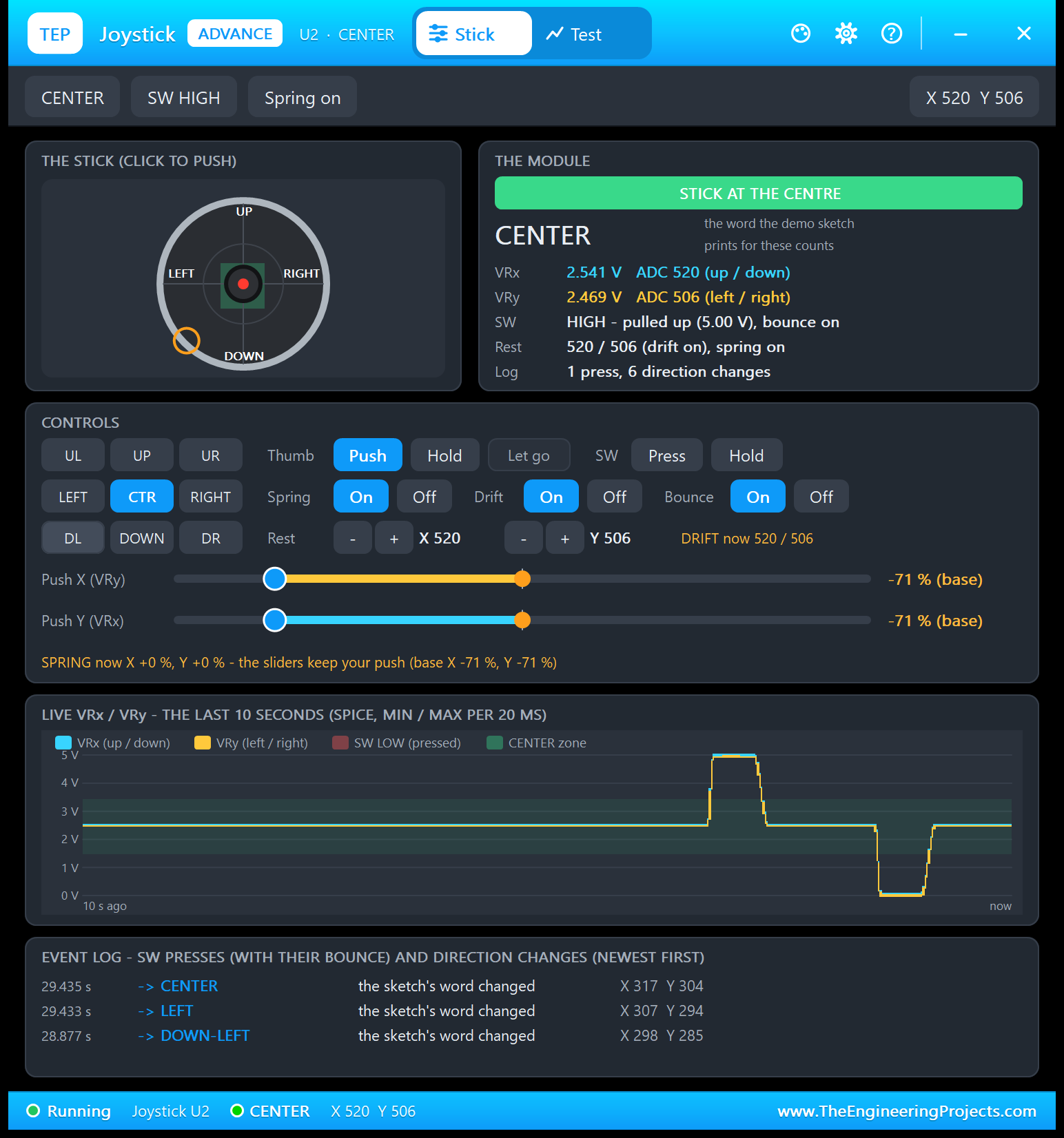
The spring moves the stick on its own, so the sliders keep the push you set. Here I clicked DL with the thumb on Push, which set both sliders to -71 %. After 0.5 s the spring took the stick back. The sliders still say "-71 % (base)", their amber marks sit at 0, where the stick is now, an amber ring in the stick view marks the base, and the line below says "SPRING now X +0 %, Y +0 % - the sliders keep your push". THE MODULE is back at STICK AT THE CENTRE: 2.541 V = 520 and 2.469 V = 506. With the thumb on Hold, the stick stays at the sliders' place until you click Let go.
The chart shows both moves: up to 5 V and back (UP-RIGHT), then down to 0 V and back (DOWN-LEFT). The event log caught a detail: on the way back from DOWN-LEFT, the word was LEFT for 2 ms (X 307 Y 294) before CENTER (X 317 Y 304). VRx rests higher than VRy (520 against 506), so it left the DOWN side first. A real sketch can catch such short in-between words too.
The Test Page: Four Measured Joystick Test Tools
The four tools on the Test tab answer the questions you have when you write a joystick sketch: where is the centre, how big must the dead zone be, how much does the button bounce, and does my direction table work? A tool takes the stick over, measures the VRx, VRy and SW node voltages of the running circuit at every simulation step, and puts the scene back when it ends. Each tool ends with a bold "Good for:" line. A tool refuses to start, with the reason, when the joystick has no power or another test is running. All results below come from U2, with the demo sketch running.
1. Axis Sweep: Centre, Slope and Where It Saturates
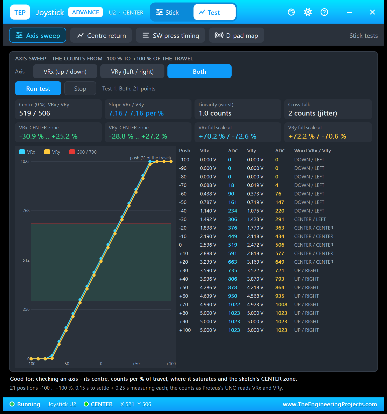
Good for: "checking an axis - its centre, counts per % of travel, where it saturates and the sketch's CENTER zone." Choose VRx, VRy or Both and click Run test. The tool waits for a flat reading at -100 %, then pushes the stick to 21 positions from -100 to +100 % of the travel, with 0.15 s to settle and 0.25 s of measuring at each. With Both:
- Centre (0 %): 519 / 506; slope: 7.16 / 7.16 counts per % of the travel, linear within 1.0 count.
- Cross-talk: 2 counts (jitter): pushing one axis does not move the other.
- Full scale: VRx reaches 1023 at +70.2 % and 0 at -72.6 %; VRy at +72.2 / -70.6 %.
- CENTER zone: VRx -30.9 .. +25.2 %, VRy -28.8 .. +27.2 % of the travel.
| Push | VRx | ADC | VRy | ADC | Word VRx / VRy |
|---|---|---|---|---|---|
| -80 % | 0.000 V | 0 | 0.000 V | 0 | DOWN / LEFT |
| -70 % | 0.088 V | 18 | 0.019 V | 4 | DOWN / LEFT |
| -30 % | 1.492 V | 306 | 1.423 V | 291 | CENTER / LEFT |
| 0 % | 2.536 V | 519 | 2.472 V | 506 | CENTER / CENTER |
| +20 % | 3.239 V | 663 | 3.169 V | 649 | CENTER / CENTER |
| +30 % | 3.590 V | 735 | 3.522 V | 721 | UP / RIGHT |
| +70 % | 4.990 V | 1022 | 4.923 V | 1008 | UP / RIGHT |
| +80 % | 5.000 V | 1023 | 5.000 V | 1023 | UP / RIGHT |
Why is the CENTER zone not symmetric? VRx rests at about 520: 180 counts below 700 but 220 above 300. At 7.16 counts per %, the word turns UP after 25 % of the travel, but DOWN only after 31 %. At -30 %, VRx (306) is still CENTER, while VRy (291) is already LEFT.
2. Centre Return: How Big a Dead Zone Do You Need?
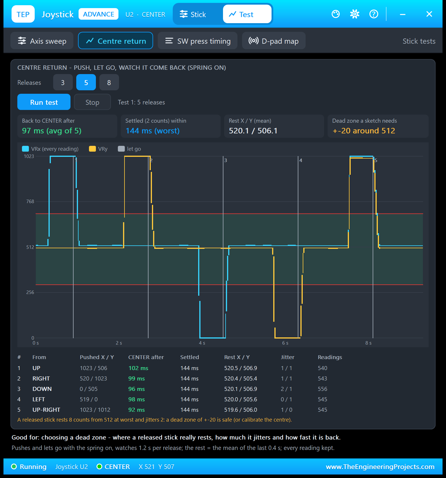
Good for: "choosing a dead zone - where a released stick really rests, how much it jitters and how fast it is back." Choose 3, 5 or 8 releases. The tool pushes the stick for 0.6 s, lets go with the spring on, and keeps every reading for 1.2 s after each release. The grey lines in the chart mark the moments it lets go.
| # | From | Pushed X / Y | CENTER after | Settled | Rest X / Y | Jitter |
|---|---|---|---|---|---|---|
| 1 | UP | 1023 / 506 | 102 ms | 144 ms | 520.5 / 506.9 | 1 / 1 |
| 2 | RIGHT | 520 / 1023 | 99 ms | 144 ms | 520.4 / 505.4 | 1 / 1 |
| 3 | DOWN | 0 / 505 | 96 ms | 144 ms | 520.1 / 506.9 | 2 / 1 |
| 4 | LEFT | 519 / 0 | 98 ms | 144 ms | 520.0 / 505.6 | 0 / 1 |
| 5 | UP-RIGHT | 1023 / 1012 | 92 ms | 144 ms | 519.6 / 506.0 | 1 / 0 |
The stick is back in the CENTER zone after 97 ms on average and settled within 144 ms; the mean rest is 520.1 / 506.1. The verdict: "A released stick rests 8 counts from 512 at worst and jitters 2: a dead zone of +-20 is safe (or calibrate the centre)." So a sketch that treats ±20 counts around 512 as "not pushed" never sees a ghost movement from this stick. The demo's much wider zone (300 to 700) is safe too, but needs a push of about 25 to 31 %.
3. SW Press Timing: Bounce and Debounce
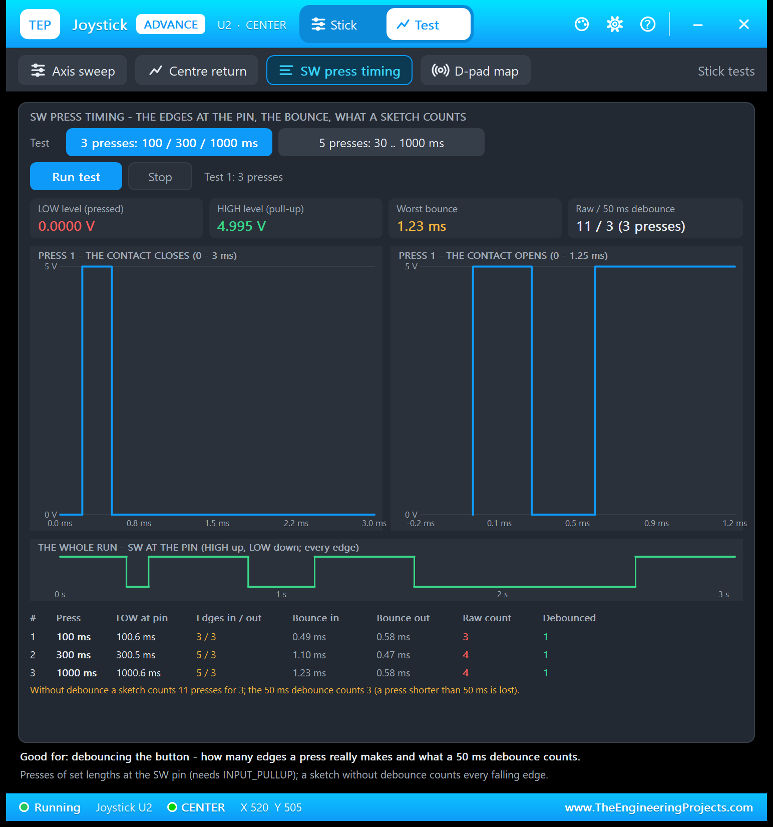
Good for: "debouncing the button - how many edges a press really makes and what a 50 ms debounce counts." First the tool checks the pull-up: if SW floats, it stops with "the sketch needs pinMode(SW, INPUT_PULLUP)". Then it presses the button for set times, 3 presses (100 / 300 / 1000 ms) or 5 (30 .. 1000 ms), and records every edge at the pin. The tiles give LOW 0.0000 V, HIGH 4.995 V (the UNO's pull-up) and the worst bounce, 1.23 ms.
The two zoom charts show press 1 sample by sample. THE CONTACT CLOSES: SW falls to 0 V, jumps back to 5 V for a moment, and falls again for good at 0.49 ms. THE CONTACT OPENS: SW rises to 5 V, drops back to 0 V, and rises for good at 0.58 ms. THE WHOLE RUN chart below shows SW low for 100, 300 and 1000 ms.
| # | Press | LOW at pin | Edges in / out | Bounce in | Bounce out | Raw count | Debounced |
|---|---|---|---|---|---|---|---|
| 1 | 100 ms | 100.6 ms | 3 / 3 | 0.49 ms | 0.58 ms | 3 | 1 |
| 2 | 300 ms | 300.5 ms | 5 / 3 | 1.10 ms | 0.47 ms | 4 | 1 |
| 3 | 1000 ms | 1000.6 ms | 5 / 3 | 1.23 ms | 0.58 ms | 4 | 1 |
Read press 1 like this: the contact made 3 edges when it closed (2 of them falling) and 3 edges when it opened (1 more falling), exactly what the zooms show. A sketch that counts falling edges without debounce sees 3 presses for one; presses 2 and 3, with 5 edges in, count 4 each. Over the whole run, that is 11 presses for 3, while a 50 ms debounce counts exactly 3; the catch is that a press shorter than 50 ms is lost. The demo's INT0 interrupt counts the same falling edges (type PRESSES).
4. D-pad Map: Does Your Direction Table Work?
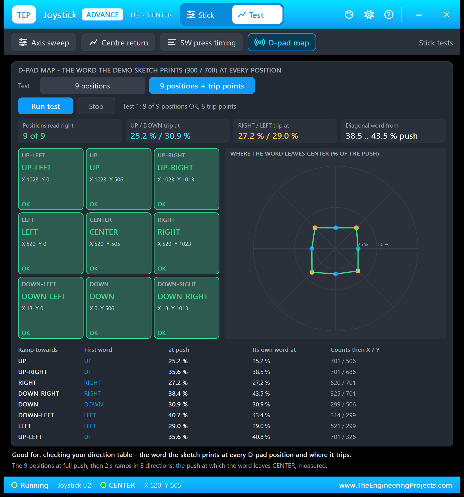
Good for: "checking your direction table - the word the sketch prints at every D-pad position and where it trips." The tool sets the 9 positions at full push and checks the word the demo sketch would print: 9 of 9 tiles are green, from UP-LEFT (X 1023 Y 0) to DOWN-RIGHT (X 13 Y 1013). With "9 positions + trip points", it then ramps the stick from the centre in the 8 directions for 2 s each and measures the push at which the word leaves CENTER:
| Ramp towards | First word | At push | Its own word at | Counts then X / Y |
|---|---|---|---|---|
| UP | UP | 25.2 % | 25.2 % | 701 / 506 |
| UP-RIGHT | UP | 35.6 % | 38.5 % | 701 / 686 |
| RIGHT | RIGHT | 27.2 % | 27.2 % | 520 / 701 |
| DOWN-RIGHT | RIGHT | 38.4 % | 43.5 % | 325 / 701 |
| DOWN | DOWN | 30.9 % | 30.9 % | 299 / 506 |
| DOWN-LEFT | LEFT | 40.7 % | 43.4 % | 314 / 299 |
| LEFT | LEFT | 29.0 % | 29.0 % | 521 / 299 |
| UP-LEFT | UP | 35.6 % | 40.8 % | 701 / 326 |
The diagonals are the interesting rows. On a diagonal, each axis gets 0.707 of the push (the cosine of 45 degrees), so VRx needs 25.2 / 0.707 = 35.6 % before it passes 700, and VRy needs 27.2 / 0.707 = 38.5 %. That is why a push towards UP-RIGHT first prints UP and only later UP-RIGHT. If your game needs clean diagonals, make the zone narrower, or decide the direction from the angle instead of two separate limits.
Settings and Help
The gear icon opens Settings:
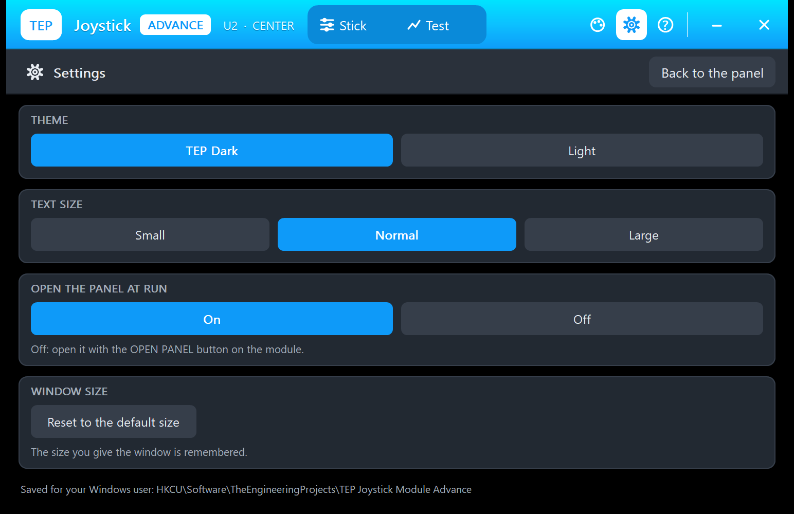
Choose the theme (TEP Dark or Light), the text size (Small, Normal or Large) and whether the window opens at Run. With Off, you open it with the OPEN PANEL button on the module. "Reset to the default size" undoes your resizing; the size you give the window is remembered. Everything is saved for your Windows user, and "Back to the panel" returns to the Stick or Test page.
The ? icon opens Help & Support, like the TEP Serial Monitor's:
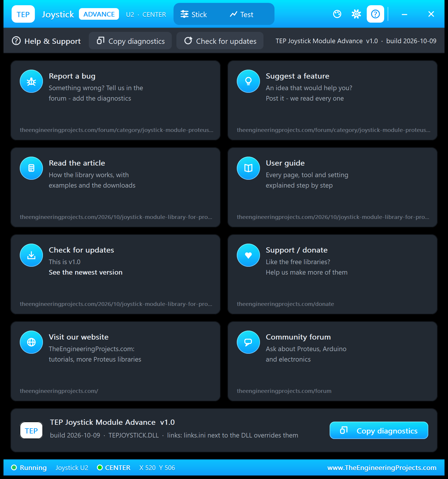
Eight cards: Report a bug and Suggest a feature open the Joystick Module board of our forum, Read the article, User guide and Check for updates ("This is v1.0") open this article, and the others open the donate page, our website and the forum. Copy diagnostics copies the stick, the log and the test results for a bug report, and a links.ini next to the DLL can change the links.
Joystick Direction Demo with Arduino in Proteus
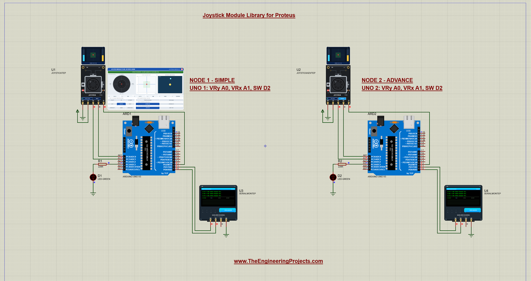
Open Joystick-Module-ArduinoUnoV3.pdsprj from the Proteus Simulation folder, with Joystick_Direction_Demo.hex and both DLLs beside it. Its two Arduino UNOs from our Arduino Library for Proteus V3.0 run the same HEX file:
- NODE 1 - SIMPLE: UNO 1 (ARD1) with the Joystick Simple (U1), the green LED D1 on A3 and Serial Monitor U3.
- NODE 2 - ADVANCE: UNO 2 (ARD2) with the Joystick Advance (U2), the green LED D2 on A3 and Serial Monitor U4.
Wiring
| From | To | Why |
|---|---|---|
| Joystick GND / +5V | Ground / power terminal | Power for both pots (the PWR LED lights) |
| Joystick VRy | Arduino A0 | Left / right |
| Joystick VRx | Arduino A1 | Up / down |
| Joystick SW | Arduino D2 (INT0) | The button, with the UNO's INPUT_PULLUP; INT0 counts every falling edge |
| LED + 220 Ω | A3 to GND | Lights while the stick is pressed (the UNO's D13 LED too) |
| Serial Monitor RXD / TXD / GND | Arduino D1 / D0 / ground | Shows what the Arduino prints, sends what you type |
| Serial Monitor RXD2 | Not connected | The joystick has no serial line to watch |
Many tutorials wire VRx to A0 and VRy to A1. In our demo, VRx goes to A1 and VRy to A0: the joystick sits left of the UNO, its pins run GND, +5V, VRx, VRy, SW, and A0 is above A1, so this way the wires do not cross. Any analog pins work; just change PIN_X and PIN_Y. SW goes to D2, the UNO's external interrupt INT0 (see our Introduction to Arduino UNO for the pin map).
The Arduino Code
The demo sketch, Joystick_Direction_Demo.ino, uses no extra library. It starts with the pins. Note VRx on A1 and VRy on A0, as wired:
const int PIN_X = A1;          // VRx (up / down)
const int PIN_Y = A0;          // VRy (left / right)
const int PIN_SW = 2;          // SW (push button, active LOW) - D2 is also INT0
const int PIN_LED = 13;        // the UNO's on-board LED
const int PIN_LED2 = A3;       // the demo's green LED (220 ohm to GND)
The CENTER zone is two limits. Between them, an axis counts as "not pushed":
int lowLimit = 300;            // below this an axis counts as pushed to its 0 side
int highLimit = 700;           // above this an axis counts as pushed to its 1023 side
                               // (300 .. 700 = the CENTER zone: a real stick never rests at exactly 512)
In setup(), the sketch switches on the UNO's own pull-up for SW, because the module has none, and attaches the INT0 interrupt to every falling edge of SW. Then it prints the three start lines:
void setup() {
  Serial.begin(9600);
  pinMode(PIN_SW, INPUT_PULLUP);       // no pull-up on the module: use the UNO's own
  pinMode(PIN_LED, OUTPUT);
  pinMode(PIN_LED2, OUTPUT);
  attachInterrupt(digitalPinToInterrupt(PIN_SW), onFall, FALLING);
  Serial.println("Joystick Direction Demo - The Engineering Projects");
  Serial.println("Move the stick (click / drag it in the Proteus panel) and press it.");
  Serial.println("Joystick Module Library for Proteus - type HELP for the commands");
}
The interrupt only counts; the main code reads the counter with interrupts briefly off:
void onFall() { fallEdges++; }

unsigned long edgesNow() {
  noInterrupts();
  unsigned long n = fallEdges;
  interrupts();
  return n;
}
The heart of the demo turns the two counts into a word. With CAL on, the counts are first shifted so that the calibrated centre becomes 512:
const char* directionWord(int x, int y) {
  if (calibrated) { x = x - calX + 512; y = y - calY + 512; }
  static char word[16];
  const char* vertical = "";
  const char* horizontal = "";
  if (x > highLimit) vertical = "UP";
  if (x < lowLimit) vertical = "DOWN";
  if (y > highLimit) horizontal = "RIGHT";
  if (y < lowLimit) horizontal = "LEFT";

  if (vertical[0] == 0 && horizontal[0] == 0) return "CENTER";
  if (vertical[0] == 0) return horizontal;
  if (horizontal[0] == 0) return vertical;
  strcpy(word, vertical);                // a diagonal, e.g. "UP-LEFT"
  strcat(word, "-");
  strcat(word, horizontal);
  return word;
}
The button is polled in every loop, with the debounce of the Arduino "Debounce" example: a new level counts only after it stayed for debounceMs (50 ms):
void pollButton() {
  bool reading = digitalRead(PIN_SW) == LOW;
  unsigned long now = millis();
  if (reading != swReading) { swReading = reading; swChangedAt = now; }
  if (swReading != swPressed && now - swChangedAt >= debounceMs) {
    swPressed = swReading;
When a press is accepted, the sketch also says how many falling edges INT0 counted since the last release. That is the bounce you saw in the event log:
    if (swPressed) {
      presses++;
      unsigned long edges = edgesNow() - fallsAtRelease;
      Serial.print("Press ");
      Serial.print(presses);
      if (edges > 1) {
        Serial.print(" - the pin fell ");
        Serial.print(edges);
        Serial.println(" times (contact bounce)");
      } else {
        Serial.println();
      }
    } else {
      fallsAtRelease = edgesNow();
    }
A reading is two analogRead() calls and one line on the Serial Monitor:
void printReading() {
  int x = analogRead(PIN_X);            // 0 .. 1023
  int y = analogRead(PIN_Y);            // 0 .. 1023
  lastX = x; lastY = y;
  readings++;
  Serial.print("X: ");
  Serial.print(x);
  Serial.print("   Y: ");
  Serial.print(y);
  Serial.print("   Button: ");
  Serial.print(swPressed ? "PRESSED " : "released");
  Serial.print("   Direction: ");
  Serial.println(directionWord(x, y));
}
The loop never waits with delay(), so no press is missed; it prints a reading every 250 ms:
void loop() {
  pollButton();
  serialCommands();
  if (every && millis() - lastPrint >= every) {   // print 4 times a second (EVERY changes it)
    lastPrint = millis();
    printReading();
  }
}
CAL takes the centre from 16 readings of the stick at rest, rounded, so the CENTER zone moves with your stick's real rest values:
  if (!strcmp(s, "CAL")) {
    long sx = 0, sy = 0;
    for (int i = 0; i < 16; i++) { sx += analogRead(PIN_X); sy += analogRead(PIN_Y); }
    calX = (sx + 8) / 16; calY = (sy + 8) / 16;
    calibrated = true;
    Serial.print("Centre calibrated: X ");
    Serial.print(calX);
    Serial.print("  Y ");
    Serial.print(calY);
    Serial.println(" - the zone moves with it");
    return;
  }
HELP prints two short lines, so they fit the Serial Monitor's Simple interface:
void help() {
  Serial.println("Commands: HELP, STATUS, READ, EVERY ms (0 = pause), PRESSES,");
  Serial.println("  LIMITS lo hi, CAL (centre = now), CAL OFF, DEBOUNCE ms (0 - 500)");
}
To change the sketch, export a new HEX file and load it into both UNOs; see How to get the HEX file from Arduino. New to Arduino? Start with our Arduino Tutorial for Beginners.
Serial Monitor Commands
| Command | What it does |
|---|---|
| HELP | The command list (two lines) |
| STATUS | The reading interval, the CENTER zone, the debounce, CAL, the last reading, the presses and readings so far |
| READ | One reading now |
| EVERY ms | The reading interval, 100 to 10000 ms (0 = pause; start: 250 ms) |
| PRESSES | The debounced presses and every falling edge at the SW pin, counted by INT0 |
| LIMITS lo hi | The CENTER zone (0 < lo < hi < 1023; start: 300 700) |
| CAL / CAL OFF | The centre = the stick's rest now (the zone moves with it) / the zone around 512 again |
| DEBOUNCE ms | The button's debounce, 0 to 500 ms (0 = every edge is a press; start: 50 ms) |
How to Run the Demo
- Press Run. Both Serial Monitors (9600 baud) and U2's pop-up open, and the PWR LEDs light.
- On U1's panel, click UP and UP-RIGHT, drag the cap, then try PRESS, HOLD, SPRING OFF and DRIFT OFF.
- Click the monitors' quick buttons (full view) or type commands: STATUS, PRESSES, DEBOUNCE 0 (then press the stick), DEBOUNCE 50, CAL, HELP.
- On U2, try the Stick page, then the four tools on the Test tab, while U4 shows what the sketch sees.
- Close U2's window and reopen it with OPEN PANEL; close U1's panel with its red X and reopen it with PANEL.
Joystick Proteus Simulation Results
The Serial Monitor in Its Simple Interface
Both monitors in this demo run in the Simple interface of our TEP Serial Monitor, as in every monitor screenshot here. Only the log, the send box and one slim toolbar row stay visible (baud rate, follow, pause, search and clear), so the window stays small.
- Switch to it: right-click the log and choose Simple interface, or press Ctrl+Shift+U.
- Back to the full view: click the corner button (the expand arrows at the top right), press Esc or Ctrl+Shift+U, or right-click and choose Full interface.
- Your choice is remembered.
Type commands in the send box and press Enter; the quick buttons come back with the full view. Every line the demo prints is shorter than 80 characters, so it fits this small window. Read all about the monitor in TEP Serial Monitor Advance for Proteus.
Start-Up and the Drift
After Run, U3 and U4 print the three start lines of setup():
Joystick Direction Demo - The Engineering Projects
Move the stick (click / drag it in the Proteus panel) and press it.
Joystick Module Library for Proteus - type HELP for the commands
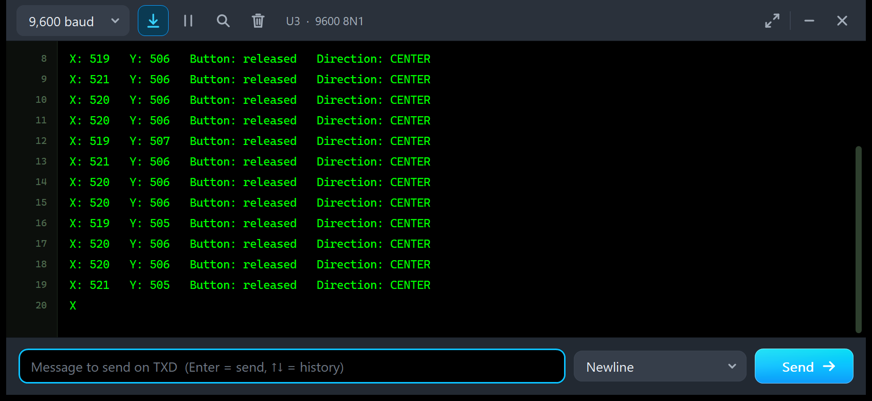
Then a reading comes four times a second. In this picture, the start lines have already scrolled away:
X: 519   Y: 506   Button: released   Direction: CENTER
X: 521   Y: 506   Button: released   Direction: CENTER
X: 520   Y: 506   Button: released   Direction: CENTER
X: 520   Y: 506   Button: released   Direction: CENTER
X: 519   Y: 507   Button: released   Direction: CENTER
X: 521   Y: 506   Button: released   Direction: CENTER
X: 520   Y: 506   Button: released   Direction: CENTER
X: 520   Y: 506   Button: released   Direction: CENTER
X: 519   Y: 505   Button: released   Direction: CENTER
X: 520   Y: 506   Button: released   Direction: CENTER
X: 520   Y: 506   Button: released   Direction: CENTER
X: 521   Y: 505   Button: released   Direction: CENTER
The stick is not touched, but X moves between 519 and 521 and Y between 505 and 507: the drift with its jitter, like a real stick. The word stays CENTER.
UP-RIGHT, the Spring and DOWN-LEFT
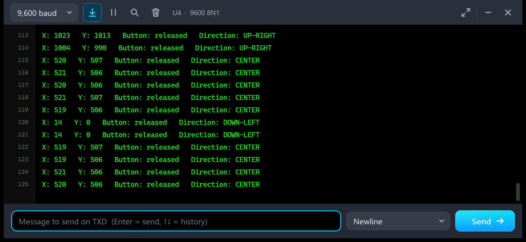
X: 1023   Y: 1013   Button: released   Direction: UP-RIGHT
X: 1004   Y: 990   Button: released   Direction: UP-RIGHT
X: 520   Y: 507   Button: released   Direction: CENTER
X: 521   Y: 506   Button: released   Direction: CENTER
X: 520   Y: 506   Button: released   Direction: CENTER
X: 521   Y: 507   Button: released   Direction: CENTER
X: 519   Y: 506   Button: released   Direction: CENTER
X: 14   Y: 0   Button: released   Direction: DOWN-LEFT
X: 14   Y: 0   Button: released   Direction: DOWN-LEFT
X: 519   Y: 507   Button: released   Direction: CENTER
X: 519   Y: 506   Button: released   Direction: CENTER
X: 521   Y: 506   Button: released   Direction: CENTER
X: 520   Y: 506   Button: released   Direction: CENTER
These are two clicks on U2's D-pad. UR gives X: 1023 Y: 1013, the round gate again. The second line, X: 1004 Y: 990, was read as the spring started to bring the stick back: the outputs follow every simulation step, so a sketch can catch the stick in motion. DL gives X: 14 Y: 0: VRx starts higher (520), so it stops 14 counts short of 0.
Presses, STATUS and PRESSES
Press the stick with PRESS on U1, then click STATUS and PRESSES on U3. The README of the package shows an example of what you get (the counts change by one or two, and the edges per press depend on the bounce):
X: 1023   Y: 506   Button: released   Direction: UP
X: 519   Y: 506   Button: released   Direction: CENTER
Press 1 - the pin fell 2 times (contact bounce)
X: 521   Y: 507   Button: PRESSED    Direction: CENTER
Status: every 250 ms, CENTER zone 300 - 700, debounce 50 ms, no CAL
  last: X 520  Y 506  CENTER, presses 1, readings 25
Presses: 1 counted (debounce 50 ms), 2 falling edges at the pin
In our Proteus run, the press from the Advance pop-up printed "Press 1 - the pin fell 4 times (contact bounce)" on U4: four falling edges, but one press, thanks to the 50 ms debounce. Type DEBOUNCE 0 and press again: every bounce becomes its own "Press" line, just as on a real board when a sketch forgets to debounce.
Troubleshooting
- The button reads LOW all the time, or "PRESSED" flickers: SW floats (no pull-up on the KY-023). Use
pinMode(SW, INPUT_PULLUP); the Simulation Log says "SW is not pulled up" once. - One press is counted 2 to 4 times: the contact bounce. Debounce, or set BOUNCE OFF for clean edges.
- Directions swapped or mirrored: that is how the module is held. Swap the axes or the signs in your sketch.
- The stick at rest does not read 512: the centre drift. Use a dead zone or CAL, or set DRIFT OFF.
- The panel and the sketch differ by one count while the stick moves: the panel shows its last refresh, the sketch its own moment.
- The part is not simulated, no panel or no monitor window: TEPJOYSTICK.DLL or TEPSERIALMON.DLL is missing from MODELS and the project folder; click OPEN MONITOR on a closed monitor.
- The Advance pop-up does not appear: click OPEN PANEL on the board, or turn "Open the panel at Run" back on in Settings.
- Your sketch waits for SW with a pin-change interrupt and nothing happens: Proteus 8.5's ATmega328P does not run pin-change interrupts. Use digitalRead, or attachInterrupt on D2 (INT0) or D3 (INT1).
Things to Know Before Using a Real KY-023 Joystick
The demo sketch uses no extra library, so it runs on a real UNO and KY-023, too. Keep in mind:
- Supply: 3.3 to 5 V; VRx and VRy follow the supply (ratiometric). With 3.3 V on the module and a 5 V UNO, the centre reads about 338, not 512.
- Orientation: with the pins down, UP = VRx 1023 and RIGHT = VRy 1023.
- The centre: a real stick rests a few counts off 512 (often 490 to 530) and jitters: use a dead zone or calibrate (CAL).
- The travel: the pots reach 0 and 1023 well before the end of the travel; a diagonal gives about 0.7 of the full travel on each axis.
- No pull-up on SW: some boards have an empty place for one. Without INPUT_PULLUP, or a 10 k resistor to +5V, SW floats.
- Bounce: one press can make several edges, so debounce (the demo uses 50 ms).
- ADC rounding: a real UNO truncates, so it may read one count lower than Proteus.
Limitations of the Simulation
- Modelled: the two 10 k pot dividers (clipped at the rails), SW as a 1 Ω contact to GND (100 MΩ open, no pull-up), the supply, the 60 ms move, the spring return, the round gate, the drift with its jitter and the bounce.
- Not modelled: the pots' tolerance and wear, a mechanical dead band, the exact gate shape, the stick's friction and the PWR LED's current (the real KY-023 has no LED).
- The model is our own implementation, written from the module's published descriptions. The HEX file contains the Arduino AVR core 1.8.6, which includes LGPL-licensed code; its source code is on GitHub.
- Speed: the demo, with two UNOs, two monitors and the Advance window open, ran at about 0.4x real time in Proteus 8.5 on our PC. The times the tools measure are simulation times and are not affected.
- Tested in Proteus 8.5 in October 2026 (the demo, both panels, the four tools and every screenshot here) and with 5,752 automatic PC checks, all passed, 28 of them with the real demo sketch on two UNOs. Proteus 7 is not supported.
Want a knob instead of a stick? See our Rotary Encoder Library for Proteus. Building the classic joystick RC remote? Send the readings to another Arduino by radio with our nRF24L01 Library for Proteus or our HC-12 Library for Proteus.
So, that was all about the Joystick Module Library for Proteus. I hope the moving stick, the event log and the four test tools make the joystick much easier to understand: where it really rests, how big your dead zone must be and why its button needs a debounce. Then your joystick project works the first time you wire a real KY-023. If you use the Joystick Module Library for Proteus in a project, please share your feedback in the comments or in our forum, and if you have any questions, ask in the comments and I will help you out. Till the next tutorial, take care and have fun!