Hello friends, I hope you all are doing great. Today, I am going to share a new SIM808 Library for Proteus. The SIM808 is a very popular module because it puts a GSM/GPRS modem (GSM is the 2G mobile network for calls and SMS, GPRS is its mobile-data service) and a GPS receiver on one board, which makes it a common choice for GPS trackers, vehicle trackers and anti-theft projects. So, we have designed a complete, working SIM808 model for Proteus from scratch.
This is not just a symbol. The SIM808 in this library actually works: it answers real AT commands, sends and receives SMS, rings on incoming calls, finds satellites and gives you a GPS fix (the GPS has found enough satellites to calculate its position), and you control everything from a virtual smartphone placed right beside the module. With the library, I am also sharing a complete Arduino GPS tracker simulation: you send "LOCATION" by SMS and the Arduino replies with a Google Maps link to the module's position.
So, let's get started with the SIM808 Library for Proteus:
What is SIM808?
SIM808 is a GSM/GPRS module by SIMCom with a built-in GPS receiver (a MediaTek MT3337 GPS engine in today's R14 version; the original R13 SIM808 used the MT3336). It is a quad-band 2G (GSM) module. It is controlled over a serial port (UART) with AT commands, which are short text commands that start with "AT" (for example, AT+CSQ asks for the signal quality), exactly like the famous SIM800L and SIM900. The GPS part is also controlled with AT commands on the same serial port, so a single Arduino serial connection gives you SMS, calls and GPS positions.
- GSM part: SMS, voice calls, network registration, signal quality, network time.
- GPS part: position, altitude, speed, UTC time (world time, the same everywhere on Earth) and satellite information, read with
AT+CGNSINF, or streamed as NMEA sentences (the standard text lines, such as $GPRMC, that GPS modules send). - Typical projects: GPS trackers, vehicle and bike trackers, SMS alarm systems, remote monitoring.
Features of SIM808 Library for Proteus
Here are the main features of our SIM808 Library for Proteus:
- A real working model: the module was written from SIMCom's SIM808 hardware design, GPS application notes and AT command manual (R14.18 firmware). Every answer we could check against a real SIM808 is copied exactly, character for character. For the few answers no real SIM808 recording shows, the model copies the closest SIMCom module (for example "SMS Ready" from the SIM800). It is our own independent model, with no SIMCom or MediaTek code.
- SMS and calls: text-mode SMS (send and receive), incoming and outgoing calls, RING and caller ID (+CLIP), network registration, signal quality (CSQ, a number from 0 to 31; higher is better), operator name and network time.
- GPS: switch the GPS on with
AT+CGNSPWR, read the position withAT+CGNSINF(the real 21-field answer), get automatic position reports withAT+CGNSURC, or get a live stream of NMEA sentences (GGA, GLL, GSA, GSV, RMC, VTG) withAT+CGNSTST. The olderAT+CGPS...commands work too. - GPS satellites: a simplified set of GPS satellites as seen from the selected place, with satellites in view, satellites used, HDOP (a number that shows how accurate the position is; lower is better) and a first fix after a start-up time you can set.
- Real power-on: the SIM808 starts switched OFF and needs a PWRKEY pulse, just like the real module.
- Virtual smartphone: send SMS, make calls, change the network signal, move the module to another city and take it indoors, all with clickable buttons.
- Animations: the PWR, STA, NET and PPS LEDs work like the real board's, and signal waves show when the module is sending, receiving or searching for satellites.
- Tested: 325 automated checks on the PC (217 on the module model, 79 on two complete Proteus models and 29 running the unmodified demo sketch), plus these checks in Proteus 8.5: the start-up, the GPS fix, the LAHORE and TOKYO buttons, the SMS LOCATION, STATUS and LED ON replies, a CALL (rejected by the demo), NETWORK WEAK, NO SIGNAL and back to GOOD, INDOOR and the board's PWRKEY button. The SMS LED OFF reply and switching the module back on with the PWRKEY button were tested on the PC only, and the LONDON and NEW YORK buttons work like TOKYO but were not tested separately.
Download SIM808 Library for Proteus
Click the button below to download SIM808-GSM-GPS-Library-for-Proteus-v1.0.zip. It contains everything you need:
Download SIM808 Library for Proteus- Proteus Library Files:
TEPSIM808.LIBand our Arduino UNO V3 library for Proteus (ArduinoV3TEP.LIBandArduinoV3TEP.IDX). - Proteus Model Files:
TEPSIM808.DLL, the simulation model. - Proteus Simulation: the ready-made GPS tracker project
SIM808-GPS-Tracker-ArduinoUnoV3.pdsprj, the Arduino HEX fileSIM808_GPS_Tracker.hexand a copy ofTEPSIM808.DLL. - Arduino Code: the sketch
SIM808_GPS_Tracker\SIM808_GPS_Tracker.ino, the AltSoftSerial 1.4 library (libraries\AltSoftSerial), the TinyGPS++ 1.0.3a library by Mikal Hart (libraries\TinyGPSPlus, LGPL 2.1 or later licence; for your own NMEA projects, the demo doesn't need it), the source of the Arduino AVR core 1.8.6 (Sources\arduino-avr-core-1.8.6.tar.bz2; it contains LGPL code) and the rebuild scriptbuild-demo.ps1. - Model Source: the C++ source code of the SIM808 model (
proteus_sim808.cppandsim808_chip.hpp) andbuild-model.ps1(rebuilding needs Labcenter's VSM SDK, which is not included). - Documentation:
MODEL-NOTES.md,THIRD-PARTY-NOTICES.txt(all the licences are listed there), the board preview and screenshots. - Main folder: the detailed
README.txtandSHA256SUMS.txt(checksums of all the files).
How to Install SIM808 Library for Proteus
Follow these simple steps to add the SIM808 library in Proteus:
- Extract the whole zip file and close Proteus if it is open.
- Open the Proteus Library Files folder and copy all three files (TEPSIM808.LIB, ArduinoV3TEP.LIB and ArduinoV3TEP.IDX) into the LIBRARY folder of Proteus. On a default installation it is usually
C:\Program Files (x86)\Labcenter Electronics\Proteus 8 Professional\LIBRARY(some installations keep it inC:\ProgramData\Labcenter Electronics\Proteus 8 Professional\LIBRARY). - Open the Proteus Model Files folder and copy TEPSIM808.DLL into the MODELS folder, usually
C:\Program Files (x86)\Labcenter Electronics\Proteus 8 Professional\MODELS(orC:\ProgramData\Labcenter Electronics\Proteus 8 Professional\MODELS). - Start Proteus, open the component list (press the P button) and search for SIM808. You will find SIM808TEP under Peripherals > Wireless.
Note: The library has been tested in Proteus 8.5. If the module appears on your schematic but is not simulated when you press Run (no live phone), TEPSIM808.DLL is missing from the MODELS folder (and from the project folder; the ready-made demo also works with the copy in its own Proteus Simulation folder).
SIM808 Module in Proteus
Once you place the SIM808 in your Proteus workspace, it looks like the image below. We have designed it to look like a real SIM808 breakout board: the SIMCom module, the SIM card holder, the PWRKEY push button, four status LEDs, a GSM rubber-duck antenna and a GPS ceramic patch antenna. The smartphone on the right is part of the same symbol, not a separate component.
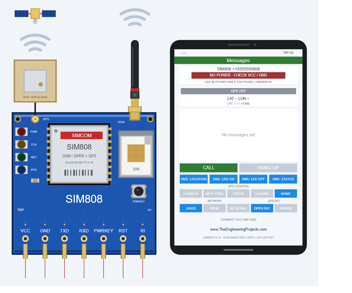
Before you press Run, the phone is only a picture: it says NO POWER - CHECK VCC / GND, GPS OFF and No messages yet, and the tip line says CONNECT VCC AND GND. It comes alive when the simulation runs. If it still says NO POWER - CHECK VCC / GND while the simulation runs, the VCC or GND pin is not connected.
The SIM808 has seven pins in Proteus. They are the signals a SIM808 breakout board gives you, but real boards put them in a different order on their headers, so always follow the labels on your own board:
| Pin | Function | Arduino (demo) |
|---|---|---|
| VCC | Power supply | +5 V terminal (simulation only) |
| GND | Ground | GND |
| TXD | Serial output of the SIM808 (answers, SMS, GPS data) | D8 (AltSoftSerial RX) |
| RXD | Serial input of the SIM808 (AT commands) | D9 (AltSoftSerial TX) |
| PWRKEY | Switches the module on / off (hold LOW for more than 1 s) | D7 |
| RST | Reset (LOW for at least 105 ms) | Not connected |
| RI | Ring indicator: LOW while a call rings, a short LOW pulse for every SMS | D2 (INT0) |
Note: In the simulation, VCC goes to a +5 V terminal. A real SIM808 needs 3.4 - 4.4 V and uses 2.8 V logic, so read "Things to Know Before Using a Real SIM808" below before you wire real hardware.
The four LEDs work like the ones on a real board:
- PWR (red): the board has power.
- STA (amber): the SIM808 is switched on.
- NET (green): blinks fast (every 0.8 s) while searching for the network and slowly (every 3 s) once registered.
- PPS (blue, pulse per second): a short flash at the start of every second while the GPS has a fix.
Above the board, two sets of wave arcs show what the radio parts are doing:
- GSM waves (above the rubber-duck antenna): grey when idle or when the module is off, orange and rippling outwards while the SIM808 sends (for example an SMS), green and rippling inwards while it receives (a new SMS or a ringing call), and both colours in turn during a call.
- GPS waves (between the satellite and the patch antenna): grey when the GPS is off or no satellite is tracked, amber while satellites are tracked but there is no fix yet, and green with a fix.
Double-click the SIM808 to open its properties. They are read when you press Run, so change them while the simulation is stopped:
| Property | Default | What it does |
|---|---|---|
| SIMNUM | +15555550808 | The module's phone number |
| PHONENUM | +15555550191 | The virtual phone's number (the demo replies to it) |
| OPERATOR | TEP MOBILE | Network name (max 20 characters) |
| SIGNAL | GOOD | Starting NETWORK button (GOOD, WEAK or NONE) |
| CLOCK | PC | PC = your PC's local time and time zone, or a fixed YYYY-MM-DD HH:MM:SS |
| POWERON | KEY | KEY = starts OFF like a bare module, AUTO = the board switches it on by itself |
| GPSLAT / GPSLON | 51.47788 / -0.00148 | The HOME position in degrees (+ = north / east) |
| GPSALT | 46 | HOME height above sea level in metres |
| GPSTTFF | 10 | Time to first fix: seconds until the first fix after a cold start (when the GPS starts from scratch); the real module needs about 30 |
Features of the SIM808 Virtual Phone
Beside the module, you will find a smartphone that comes alive when you run the simulation. It talks to the SIM808 through a simulated mobile network: the phone has the number +15555550191 and the SIM808 has +15555550808, so the phone can text and call the module by number. You use it with the mouse: just click a button. All the screenshots in this section were taken in Proteus 8.5 with the ready-made demo project, so the Arduino UNO of the next section is the one answering the phone.
To follow along, open the ready-made demo project SIM808-GPS-Tracker-ArduinoUnoV3.pdsprj from the Proteus Simulation folder of the zip (File > Open Project) and press Run. The complete setup with the Arduino UNO is shown in the section "SIM808 GPS Tracker with Arduino in Proteus" below. Two Virtual Terminals open with it (a Virtual Terminal is the Proteus version of the Arduino Serial Monitor): the Arduino's own terminal shows what the Arduino prints, and the line monitor (AT MONITOR) shows everything the SIM808 sends to the Arduino.
The Phone Screen at a Glance
From top to bottom, the phone shows:
- Top: the network clock (
--:--while the module is off); on the right, TEP 2G (the simulated 2G network), with GPS in front of it while the GPS is on; and a green Messages header that turns into a blue Phone header during a call. - Module card: the SIM808's number, a coloured state bar (for example REGISTERED - TEP MOBILE) and a small line with CSQ (the signal quality from AT+CSQ: 0 to 31, higher is better, 99 = no signal), STORED SMS (messages kept in the module's memory; 0 with the demo, which has every SMS shown directly) and THIS PHONE.
- GPS strip: the GPS state, the latitude and longitude, and a small line with the UTC time, the altitude, the HDOP and the selected place.
- Conversation: blue bubbles on the right are SMS sent by the phone, green bubbles on the left are SMS received by the phone (the Arduino's replies), and call events appear as grey text in the middle.
- Buttons and tip line: the buttons in the table below, and a tip that tells you what to do next, for example TAP A MESSAGE TO TEXT THE SIM808.
| Button | What it does |
|---|---|
| CALL / HANG UP | CALL dials the SIM808 (it reads ANSWER when the SIM808 calls the phone). HANG UP ends or rejects a call |
| SMS: LOCATION, LED ON, LED OFF, STATUS | Sends that text message to the SIM808 |
| GPS LOCATION | Moves the module to London, New York, Tokyo, Lahore or HOME (Greenwich, or your own position set in the properties) |
| NETWORK | Changes the signal: GOOD, WEAK or NO SIGNAL |
| GPS SKY | OPEN SKY or INDOOR (no GPS fix indoors) |
| PWRKEY (on the board) | Switches the module on or off, like the button on a real board |
In the GPS LOCATION, NETWORK and GPS SKY rows, the selected button is blue and the others are light grey.
Start-Up: From OFF to the First GPS Fix
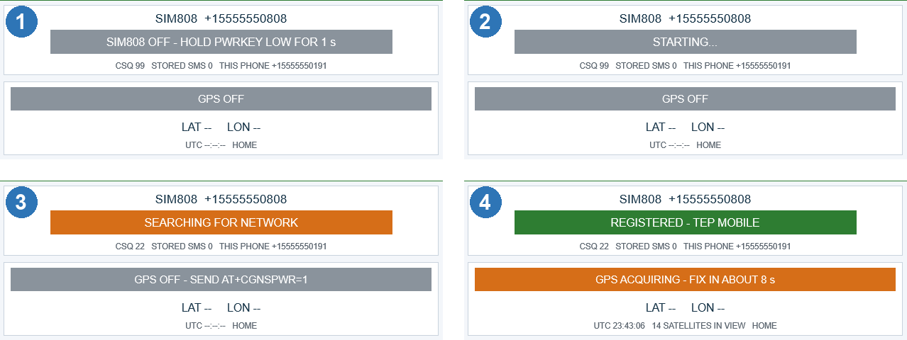
Press Run and watch the module card and the GPS strip. You don't have to click anything, because the Arduino does the work:
- SIM808 OFF - HOLD PWRKEY LOW FOR 1 s (grey), GPS OFF and CSQ 99. The module has power (the red PWR LED is on) but it is switched off, so the Arduino's first "AT" commands get no answer.
- STARTING... The Arduino has pulled PWRKEY LOW for 1.2 s (for about a second before this, the card says PWRKEY PRESSED...), and the module is booting.
- SEARCHING FOR NETWORK (orange). The module is running, the amber STA LED is on and the green NET LED blinks fast. The strip says GPS OFF - SEND AT+CGNSPWR=1, because the GPS part of the SIM808 is always off after power-up. The Arduino finds the module, waits for "SMS Ready" (a message the SIM808 sends by itself when its SMS part is ready) and sends AT+CGNSPWR=1; the strip then shows GPS: SEARCHING FOR SATELLITES for a moment.
- REGISTERED - TEP MOBILE (green) and GPS ACQUIRING - FIX IN ABOUT 8 s (orange). The module is on the network, and the GPS already sees 14 satellites and counts down to its first fix. The GPS waves turn amber, and the Arduino prints the signal, the operator, the time and "GPS: no fix yet".
A few seconds later the strip turns green with GPS 3D FIX - n OF m SATELLITES: n satellites are used for the fix out of m in view (in my first test run at Greenwich it was GPS 3D FIX - 9 OF 13 SATELLITES). A 3D fix gives latitude, longitude and altitude and needs at least 4 satellites. The position appears, the GPS waves turn green and the blue PPS LED flashes once a second. The countdown comes from the GPSTTFF property (10 s by default; a real SIM808 needs about 30 s outdoors). The satellite numbers differ from run to run, because the simulated satellites are calculated for the time of your run. A real SIM808 goes through the same steps, which is why a tracker sketch must switch the module on, then switch the GPS on, and then wait for the first fix.
SMS: LOCATION and SMS: STATUS
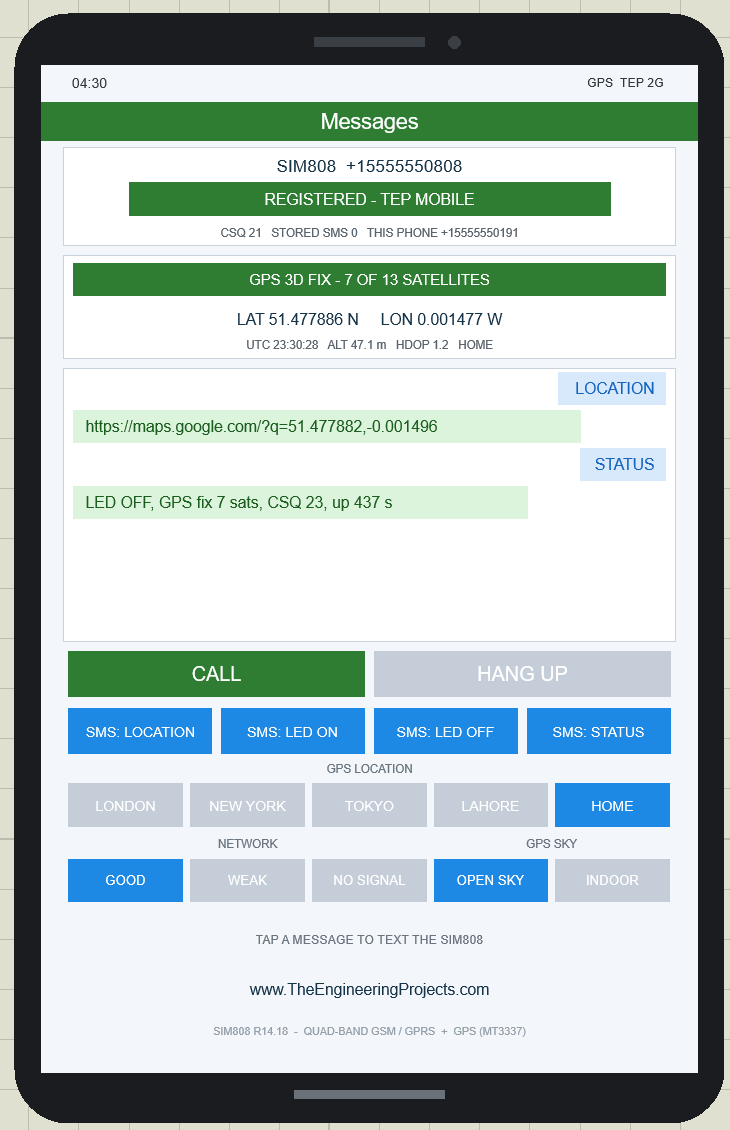
Click SMS: LOCATION. A blue LOCATION bubble appears at once. About 1.5 seconds later the SIM808 receives the text: it passes it to the Arduino as a +CMT line followed by the text, gives a short LOW pulse on its RI pin and flashes its GSM waves green. The Arduino prints "(RI pin went LOW)" and the message, reads the GPS and sends a Google Maps link back. While the SIM808 sends it, the GSM waves ripple outwards in orange, and about 2 seconds later the link appears as a green bubble, here https://maps.google.com/?q=51.477882,-0.001496, the HOME position at Greenwich.
Then click SMS: STATUS. The reply packs everything into one line: LED OFF, GPS fix 7 sats, CSQ 23, up 437 s. The LED on A0 is off, the GPS has a fix with 7 satellites used, the signal quality is 23 and the Arduino has been running for 437 seconds. The card shows CSQ 21: with GOOD signal the CSQ wobbles between 21 and 23, like the bars on a real phone, and the two values were read at slightly different moments. Also notice that the phone writes LON 0.001477 W where the link has a minus sign: W (west) and S (south) mean negative values.
For every SMS button, the Arduino's Virtual Terminal shows three lines: (RI pin went LOW), SMS from +15555550191: STATUS (the text you sent) and -> reply: with the reply, followed by (sent) once the SIM808 has sent it. This is how most SMS trackers work: the owner sends a keyword, the module hands it to the microcontroller as +CMT, and the reply goes back with AT+CMGS (the send-SMS command).
SMS: LED ON and LED OFF
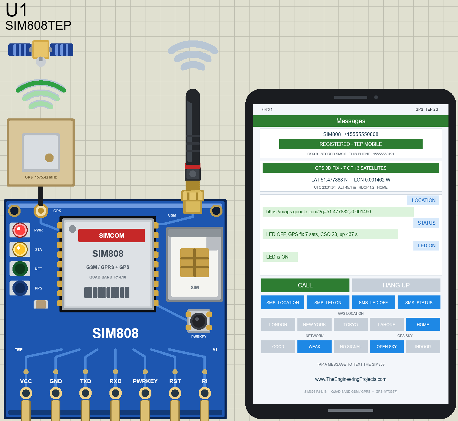
Click SMS: LED ON: the Arduino sets pin A0 HIGH and replies LED is ON. SMS: LED OFF sets it LOW and replies LED is OFF. The demo project has no LED, so add one with a 220 ohm resistor from A0 to GND if you want to see it. Even without it, the Arduino knows the pin state, so the next STATUS reply starts with "LED ON" (you will see it below).
This picture also shows the board up close: the red PWR and amber STA LEDs are on, the NET and PPS LEDs are between two flashes, the GPS waves are green (fix) and the GSM waves are grey, because the reply has already been sent.
NETWORK: GOOD, WEAK and NO SIGNAL
In the picture above (under SMS: LED ON and LED OFF), I have also clicked WEAK in the NETWORK row. The signal drops to CSQ 9 (WEAK gives 7 to 9), like a phone in a basement, but the module stays REGISTERED - TEP MOBILE, so SMS still work. They are just slower: the SIM808 needs about 5 seconds instead of 2 to send each reply, so the orange waves ripple longer, and a STATUS reply now reports a CSQ of 7 to 9. The demo prints nothing when the signal changes, because it only reads CSQ at start-up and for STATUS.
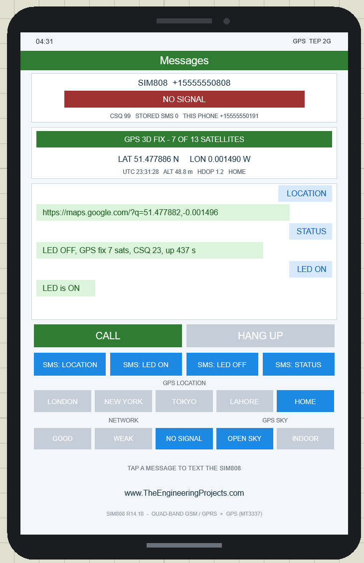
Now click NO SIGNAL. The state bar turns red, NO SIGNAL, and CSQ shows 99. The SIM808 has lost the network, and the NET LED blinks fast again, as while searching. The GPS strip still shows its fix, because the GPS gets its signals from the satellites and doesn't need the mobile network.
While there is no signal, click SMS: STATUS. The blue bubble appears, but no reply comes, and the Arduino's terminal shows nothing, because the message has not reached the SIM808 yet: it waits at the simulated SMS centre, just like a real network keeps a text for a phone that is out of coverage. A CALL fails too: after about 6 seconds the phone shows call failed - no network (this comes from the model's source; I have not tried it in Proteus).
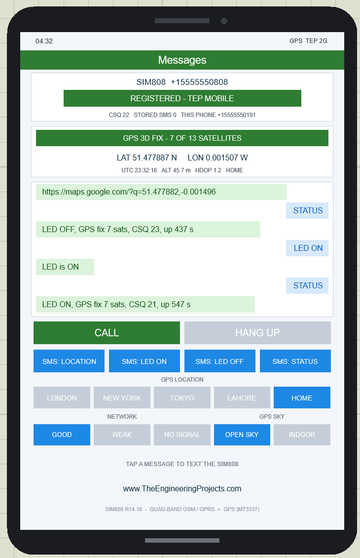
Now click GOOD. A few seconds later the module is REGISTERED again (CSQ 22 here), the waiting STATUS message is delivered and the Arduino answers it: LED ON, GPS fix 7 sats, CSQ 21, up 547 s. The Arduino's terminal now prints the RI line, the STATUS message and its reply. "LED ON" comes from the LED ON message before. The lesson for a real tracker: a text sent while the tracker has no coverage is not lost, it arrives later, so your sketch must be ready for messages at any time.
GPS SKY: OPEN SKY and INDOOR
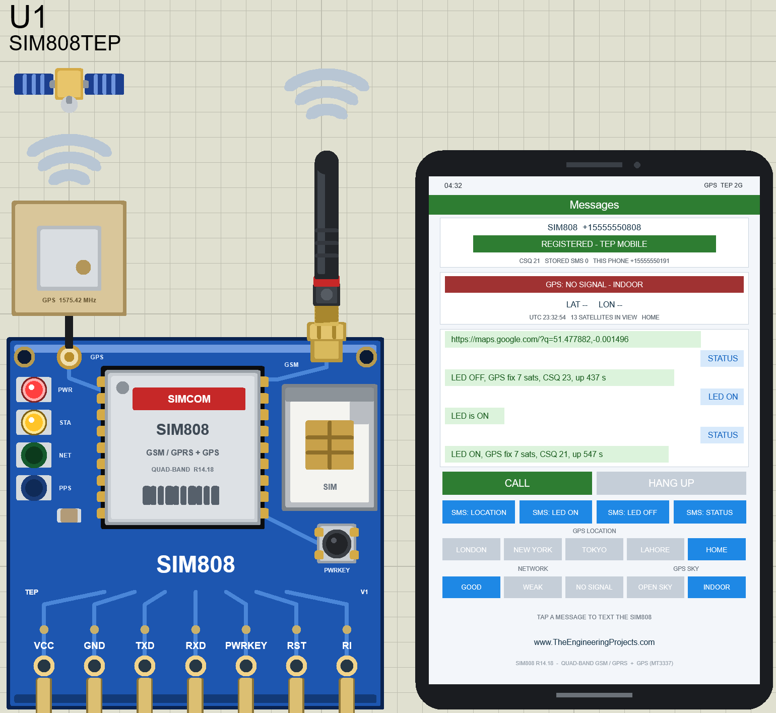
Click INDOOR in the GPS SKY row to take the module into a building. Every satellite signal becomes 40 dB (10,000 times) weaker, so the GPS can't track any satellite and loses its fix within a second. The strip turns red, GPS: NO SIGNAL - INDOOR, the position changes to LAT -- LON --, but the small line still says 13 SATELLITES IN VIEW: the satellites are still above the horizon, the GPS just can't hear them. On the board, the GPS waves turn grey and the PPS LED stops flashing. The GSM side stays REGISTERED, because INDOOR only affects the GPS. The Arduino's next GPS line becomes "GPS: no fix yet, 13 satellites in view".
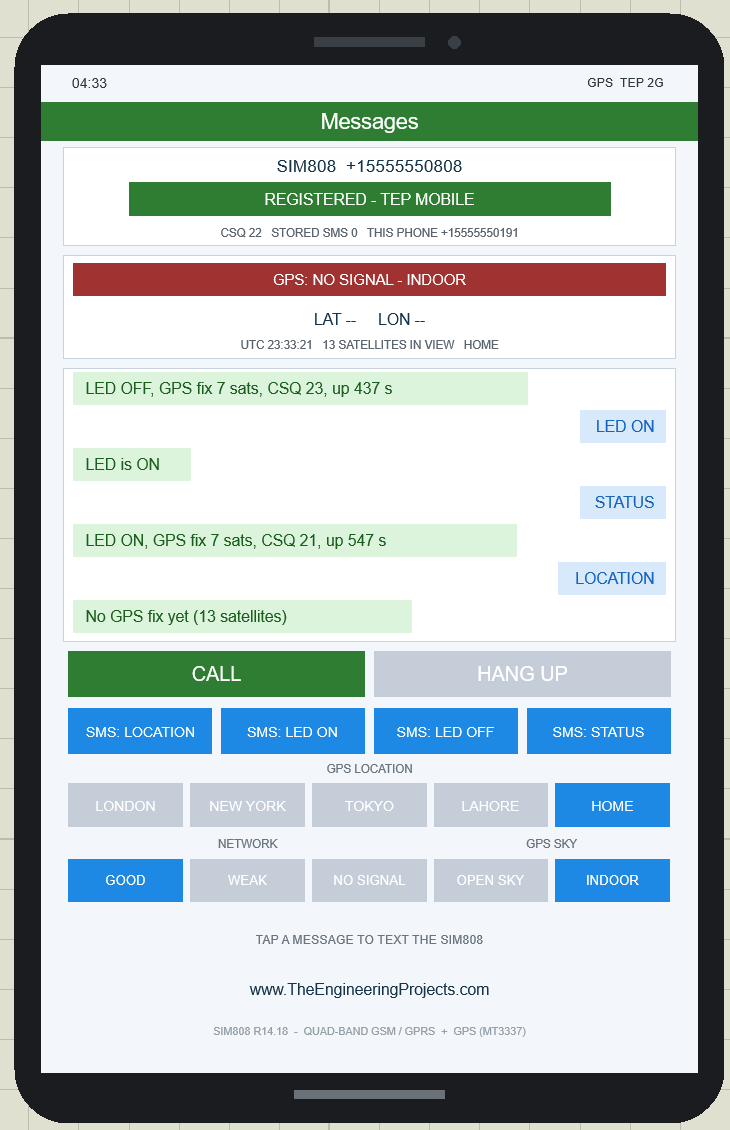
Now click SMS: LOCATION. Without a fix there is no position to send, so the Arduino replies No GPS fix yet (13 satellites). Do the same in your own tracker: always check the fix field of AT+CGNSINF (field 2) before you use the position. A real SIM808 behaves just like this: its GPS antenna needs a clear view of the sky, and there is no fix indoors.
Click OPEN SKY to go outside again, and the satellites are tracked again at once. The fix comes back within a second or two (the PC tests measured less than 3 seconds), because the receiver still knows the time and the satellites, so it is not a new cold start. In my run, I clicked OPEN SKY and then TOKYO, and the fix was already back when I took the next picture.
GPS LOCATION: Moving the Module to Tokyo
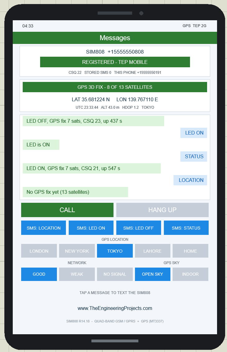
The GPS LOCATION row moves the module to another city. Click TOKYO: the button turns blue and, with a fix, the strip shows GPS 3D FIX - 8 OF 13 SATELLITES, LAT 35.681224 N LON 139.767110 E, ALT 43.0 m, HDOP 1.2 and TOKYO. The satellite numbers change with the place, because other satellites are above the horizon in Tokyo. The Arduino prints the new position in its next GPS line (every 10 seconds).
| Button | Latitude, longitude | Height above sea level |
|---|---|---|
| LONDON | 51.50735, -0.12776 | 11 m |
| NEW YORK | 40.71277, -74.00597 | 10 m |
| TOKYO | 35.68123, 139.76712 | 40 m |
| LAHORE | 31.52037, 74.35875 | 217 m |
| HOME | GPSLAT, GPSLON (default 51.47788, -0.00148, the Greenwich observatory) | GPSALT (default 46 m) |
The shown position and altitude wander a little around these values, like a real receiver's. After Stop and Run, the GPS LOCATION goes back to HOME, so set GPSLAT, GPSLON and GPSALT in the properties if you want to start at your own place.
CALL and HANG UP
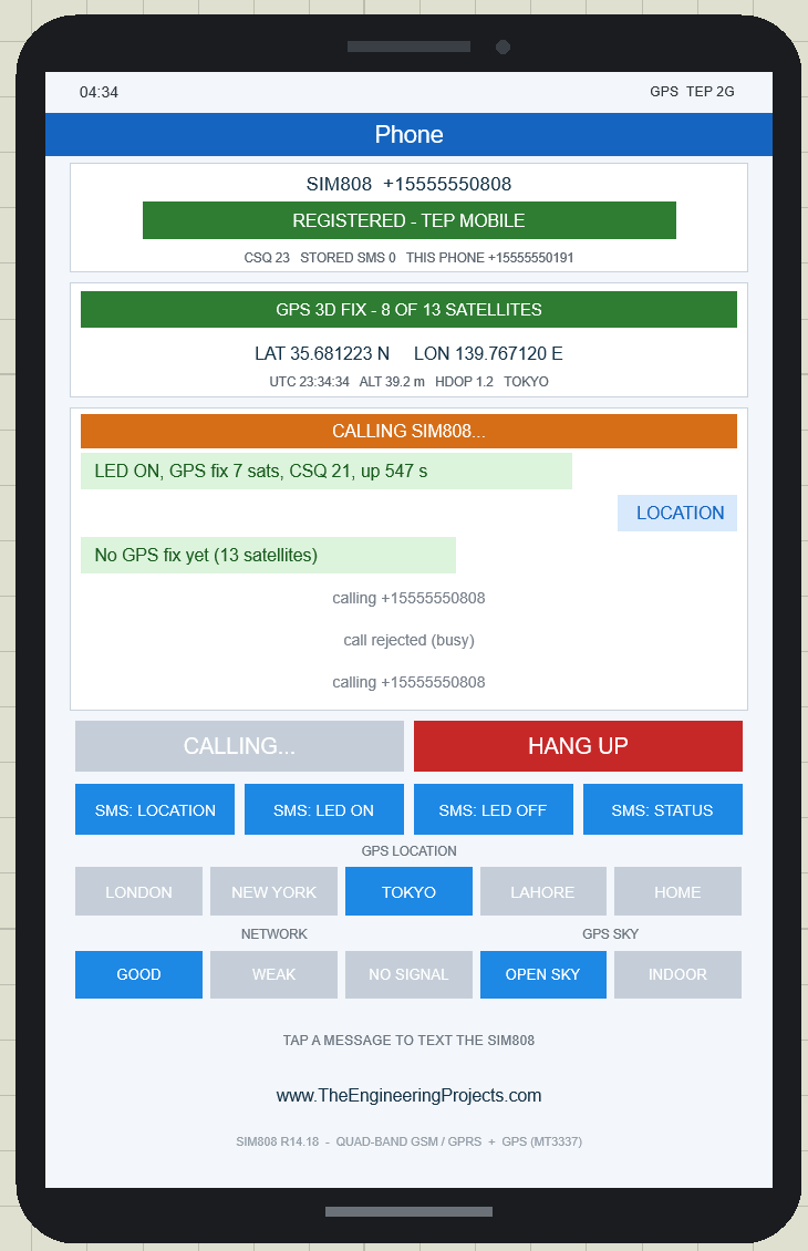
Click CALL. The phone dials the SIM808: the header turns blue and says Phone, an orange CALLING SIM808... bar appears above the messages with the line calling +15555550808, the CALL button turns grey (CALLING...) and HANG UP turns red. In this screenshot it is my second call, so the first call and its end are already in the log.
About 2 seconds later the SIM808 rings: it sends RING and, because the sketch switched the caller ID on with AT+CLIP=1, a +CLIP line with the phone's number (both appear on the line monitor), and its RI pin goes LOW. Our demo is a tracker, not a phone, so it rejects every call at once with ATH (hang up) and prints:
(RI pin went LOW)
Incoming call from +15555550191 - rejected (ATH)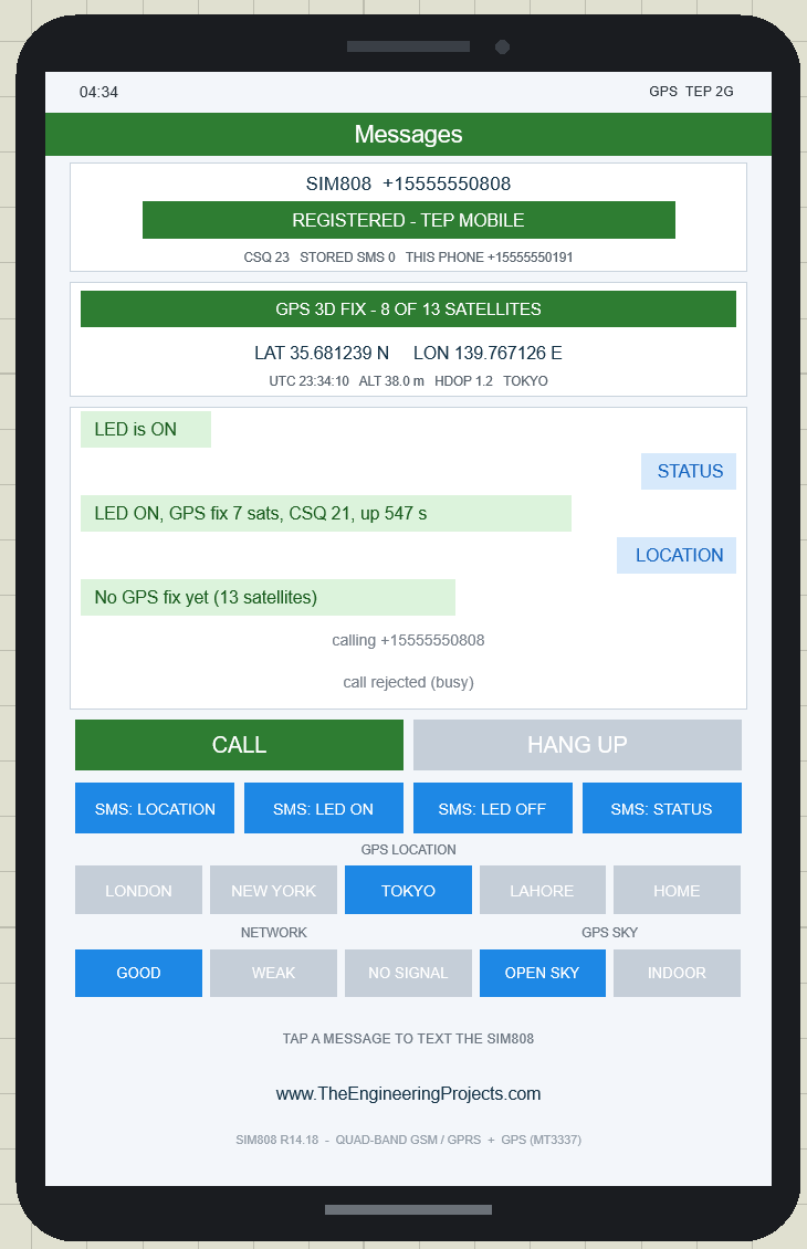
A moment later the phone shows call rejected (busy), the orange bar disappears, the header is a green Messages bar again and CALL turns green. (The picture above shows the end of my first call, so its log has only one call; the second one ended the same way.) A real SIM808 works the same way: RING and +CLIP tell your sketch who is calling, and ATH rejects the call. HANG UP ends or rejects a call from the phone side. The ANSWER button only appears when a sketch makes the SIM808 call the phone (ATD+15555550191;), and the IN CALL timer only when a call is really connected. The demo does neither, so these were tested on the PC.
The PWRKEY Button on the Board
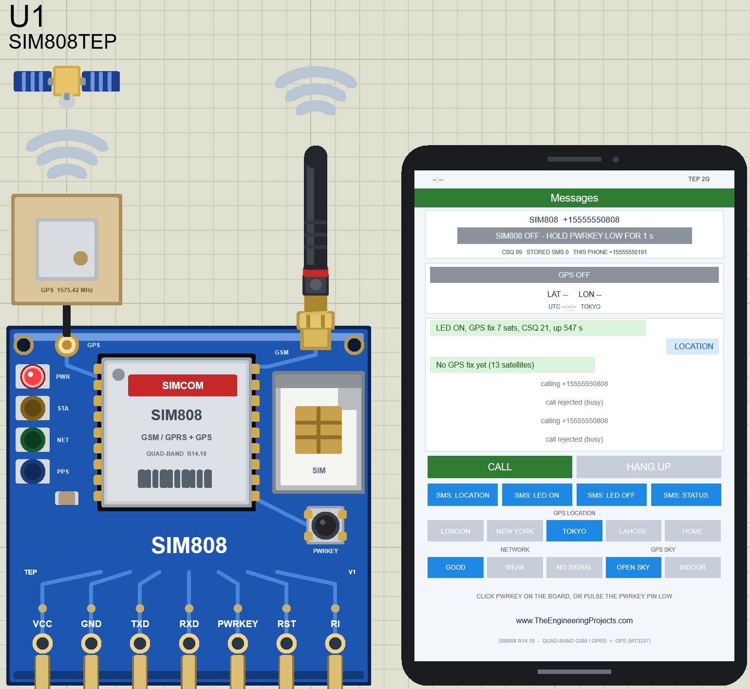
The small PWRKEY push button on the board can be clicked too. A click holds the PWRKEY pin LOW for 1.5 seconds, like pressing the button of a real board. If the module is running, it switches off: after 1 second it sends NORMAL POWER DOWN (on the line monitor) and the card turns orange for a moment, and 2 seconds after the click the module is off. In the picture, only the red PWR LED is still on, all the waves are grey, the card says SIM808 OFF - HOLD PWRKEY LOW FOR 1 s with CSQ 99, the strip says GPS OFF, the clock shows --:-- and the tip line says CLICK PWRKEY ON THE BOARD, OR PULSE THE PWRKEY PIN LOW. The messages stay. The Arduino's GPS lines should simply stop, because its AT+CGNSINF gets no answer.
Click PWRKEY again and the module starts again: PWRKEY PRESSED..., STARTING..., SEARCHING FOR NETWORK and, about 9 seconds after the click, REGISTERED (this was tested on the PC). But a restarted SIM808 starts with its default settings: the GPS is off, and the settings the sketch sent in setup() (text mode, echo off, new SMS shown directly) are gone (this comes from the model's source code; I have not checked it in a run yet). From the source, the phone should then show GPS OFF - SEND AT+CGNSPWR=1 and the tip TIP: THE SKETCH NEEDS AT+CMGF=1 (TEXT MODE), the Arduino should print "GPS: off", and a new SMS should be stored in the module (STORED SMS 1) instead of being answered.
The demo sends its set-up commands only once, so after such a restart stop and run the simulation again, or reset the Arduino UNO: the sketch then finds the module already on and sets it up again without a PWRKEY pulse (tested on the PC). The same can happen with a real module, for example when its supply drops below 3.0 V, so a good tracker sketch checks the module from time to time and sends its set-up commands again.
SIM808 GPS Tracker with Arduino in Proteus
Now let's look at a complete GPS tracker made with the SIM808 and Arduino UNO. It is ready-made in the Proteus Simulation folder of the zip. In Proteus, click File > Open Project and select SIM808-GPS-Tracker-ArduinoUnoV3.pdsprj. The Arduino HEX file (SIM808_GPS_Tracker.hex) is in the same folder and is already loaded in the Arduino UNO, so you don't need the Arduino IDE; just keep the HEX file next to the project file. If Proteus can't find it, double-click the Arduino UNO and select the HEX file in its Program File box.
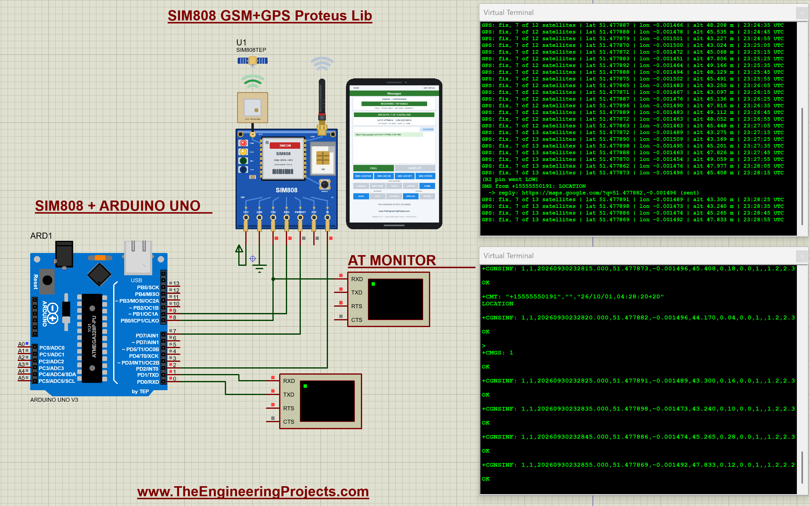
This image shows the whole setup while it runs. On the left is the Arduino UNO (ARD1, from our Arduino UNO V3 library for Proteus), at the top is the SIM808 (U1) with its phone, and below them, to the right of the Arduino, are two Virtual Terminals: the upper one, labelled AT MONITOR, sits on the SIM808's TXD line, and the lower one is the Arduino's own terminal, wired to D0 and D1. On the right, their windows are open: the Arduino's terminal at the top and the AT MONITOR at the bottom. In this run the module has a fix at HOME (7 of 13 satellites) and I have clicked SMS: LOCATION. The phone shows the LOCATION bubble and the Maps-link reply, and the Arduino's terminal tells the whole story:
GPS: fix, 7 of 13 satellites | lat 51.477873 | lon -0.001496 | alt 45.408 m | 23:28:15 UTC
(RI pin went LOW)
SMS from +15555550191: LOCATION
  -> reply: https://maps.google.com/?q=51.477882,-0.001496 (sent)
GPS: fix, 7 of 13 satellites | lat 51.477891 | lon -0.001489 | alt 43.300 m | 23:28:25 UTC
Here are the connections:
- SIM808 TXD is connected to Arduino D8 and RXD to D9.
- PWRKEY is connected to D7, so the Arduino can switch the module on.
- RI is connected to D2, the INT0 interrupt pin, so the Arduino knows immediately when an SMS or a call arrives.
- VCC goes to a +5 V power terminal and GND to ground. RST is left open (an internal pull-up, a resistor inside the module, keeps it HIGH).
- The Arduino's Virtual Terminal shows what the Arduino prints: Arduino D1 (TX) goes to the terminal's RXD. Both Virtual Terminals are set to 9600 baud (the serial speed in bits per second), the same speed as
Serial.begin(9600)andgsm.begin(9600)in the sketch. - The second Virtual Terminal, the line monitor (AT MONITOR), is connected to the SIM808's TXD line at a junction on the TXD - D8 wire. It shows everything the SIM808 sends to the Arduino, so you can see the real AT answers.
- A0: an optional LED with a 220 ohm resistor to GND for the LED ON / LED OFF messages (the demo project has none).
Why AltSoftSerial? In Proteus 8.5, the SoftwareSerial library can send data but it cannot receive anything. It needs a special kind of interrupt (the pin-change interrupt) that the Proteus ATmega328P model never runs. So the sketch uses the AltSoftSerial library (by Paul Stoffregen, MIT licence), which works in Proteus and on real boards. On the Arduino UNO its pins are fixed: RX = D8, TX = D9. Don't use D10 in your own code while it runs, because it disturbs AltSoftSerial's Timer1.
Switching the SIM808 On
The first thing you need to know is that the SIM808 starts switched OFF. Giving it power is not enough (the popular red SIM800L mini board, by contrast, starts as soon as it gets power). You have to hold its PWRKEY pin LOW for more than 1 second. About 3 seconds after PWRKEY goes LOW, the module starts answering (it stays silent until the Arduino sends "AT"). But if you press PWRKEY while the module is already on, it switches OFF! This happens, for example, when you reset the Arduino: the SIM808 is still on, and a second pulse would switch it off. So the Arduino first sends "AT", and pulses PWRKEY only if there is no answer:
// A SIM808 that is already running (after a reset of the UNO) answers the first AT. A board that
// switches it on by itself answers within about 3 s. Otherwise it is OFF: a PWRKEY pulse starts it.
// Never pulse PWRKEY while it runs - that would switch it OFF ("NORMAL POWER DOWN").
Serial.print(F("Looking for the SIM808... "));
const byte tries = findModule(8);
const bool wasOn = tries == 1;
if (wasOn) {
  Serial.println(F("already on"));
} else if (tries) {
  Serial.println(F("on (the board switched it on by itself)"));
} else {
  Serial.println(F("no answer (it starts switched OFF)"));
  Serial.println(F("Switching the SIM808 on: PWRKEY LOW for 1.2 s"));
  pinMode(PWRKEY_PIN, OUTPUT);
  digitalWrite(PWRKEY_PIN, LOW);
  delay(1200);
  pinMode(PWRKEY_PIN, INPUT);        // release
  delay(2500);                       // the serial port is ready about 3 s after PWRKEY went LOW
  if (!findModule(20)) {
    Serial.println(F("No answer from the SIM808 - check the wiring and the power supply"));
    while (true) {}
  }
}
After that, the sketch sets up the module with a few AT commands and switches the GPS on:
command("ATE0");                     // no echo
command("AT+CMEE=2");                // errors as text
command("AT+CMGF=1");                // SMS in text mode
command("AT+CNMI=2,2,0,0,0");        // print new SMS directly (+CMT:)
command("AT+CLIP=1");                // show the caller's number (+CLIP:)
Serial.print(F("GPS:      "));
Serial.println(command("AT+CGNSPWR=1") ? F("powered on (AT+CGNSPWR=1), first fix in about 30 s outdoors")
                                       : F("AT+CGNSPWR=1 failed"));
Reading the GPS Position
The GPS of the SIM808 is read with the AT+CGNSINF command. The module answers with one line of 21 comma-separated fields. Here are two answers copied from the simulation, first without and then with a fix (the second line is shortened):
+CGNSINF: 1,0,20260930215733.000,,,,0.00,0.0,0,,,,,,13,0,,,50,,
+CGNSINF: 1,1,20260930215743.000,51.477876,-0.001500,47.616,0.22,0.0,1,,0.9,1.7,1.4,...| Field | Meaning | Example |
|---|---|---|
| 1 | GPS on (1) or off (0) | 1 |
| 2 | Fix (1) or no fix (0) | 1 |
| 3 | UTC date and time (yyyyMMddhhmmss.sss) | 20260930215743.000 |
| 4, 5 | Latitude and longitude in degrees | 51.477876, -0.001500 |
| 6 | Altitude in metres | 47.616 |
| 7, 8 | Speed (km/h) and course (degrees) | 0.22, 0.0 |
| 11 - 13 | HDOP, PDOP, VDOP (lower is better) | 0.9, 1.7, 1.4 |
| 15, 16 | Satellites in view, satellites used | 13, 9 |
| 19 | Strongest satellite signal (C/N0 in dB-Hz; a bigger number is a stronger signal) | 50 |
The sketch reads this line every 10 seconds and prints the position on the Virtual Terminal:
GPS: no fix yet, 13 satellites in view
GPS: fix, 9 of 13 satellites | lat 51.477876 | lon -0.001500 | alt 47.616 m | 21:57:43 UTC
Why does my SIM808 say 1980? If you read AT+CGNSINF right after switching the GPS on, before it has found any satellites, it reports the date 1980-01-05 23:59:44, 16 seconds before the start of GPS time (6 January 1980). Once the module tracks satellites, the correct date and time appear. Our model does exactly the same.
Sending the Location by SMS
If the text that arrives with +CMT is LOCATION (or WHERE), the Arduino reads the GPS and replies with a Google Maps link:
if (!strcasecmp(text, "LOCATION") || !strcasecmp(text, "WHERE")) {
  readGps();
  if (gps.fix) snprintf_P(reply, sizeof(reply), PSTR("https://maps.google.com/?q=%s,%s"), gps.lat, gps.lon);
  else snprintf_P(reply, sizeof(reply), PSTR("No GPS fix yet (%d satellites)"), gps.inView);
} else if (!strcasecmp(text, "LED ON")) {
The other commands are LED ON, LED OFF and STATUS (it replies with the LED state, the GPS fix, the signal and the uptime). Texts the Arduino does not know get no reply, and incoming calls are shown with the caller's number and rejected. The complete, commented code is in the Arduino Code folder of the zip file.
If you want to change the code, first install the AltSoftSerial library (from the Library Manager, or copy the libraries folder from Arduino Code into your Arduino libraries folder). Then select Arduino Uno, click Sketch > Export Compiled Binary and load the new HEX file into the Arduino UNO in Proteus.
SIM808 GPS Tracker Simulation Results
Now press the Run button (the Play button at the bottom left of Proteus). The two Virtual Terminals often open on top of each other, so drag them apart. If you close a terminal by mistake, you can reopen it from the Debug menu while the simulation runs. Within about 30 seconds of simulation time (shown in the status bar at the bottom), you will see output like this on the Arduino's Virtual Terminal:
SIM808 GPS tracker - text LOCATION to get a Google Maps link
www.TheEngineeringProjects.com
Looking for the SIM808... no answer (it starts switched OFF)
Switching the SIM808 on: PWRKEY LOW for 1.2 s
SIM808 found: SIM808 R14.18
Waiting for SMS Ready... ok
GPS:      powered on (AT+CGNSPWR=1), first fix in about 30 s outdoors
Waiting for the network...... registered
Signal:   CSQ 22 (good)
Operator: TEP MOBILE
Time:     26/10/01,02:57:33+20
Ready - SMS commands: LOCATION (or WHERE), LED ON, LED OFF, STATUS
GPS: no fix yet, 13 satellites in view
GPS: fix, 9 of 13 satellites | lat 51.477876 | lon -0.001500 | alt 47.616 m | 21:57:43 UTC
Two things in this output may surprise you. The sketch's "about 30 s" is the real module's time; the simulation uses GPSTTFF (see the start-up section). And the Time line is your PC's local time (yy/MM/dd): +20 is the time zone in quarter hours (20 / 4 = UTC+5). The GPS lines use UTC (world time), so 21:57 UTC on 30 September is the same moment as 02:57 on 1 October at UTC+5.
The module has a GPS fix at the Greenwich observatory in London (the default HOME position), and the phone shows a green GPS 3D FIX line (9 OF 13 SATELLITES in this run). Your date, time, satellite counts and the last digits of the position will be different, because the clock comes from your PC and the satellites are calculated for the time of your run. Now let's move it: click LAHORE in the GPS LOCATION row. The phone's GPS strip moves to Lahore, and within 10 seconds the Arduino prints the new position. For example, in my run:
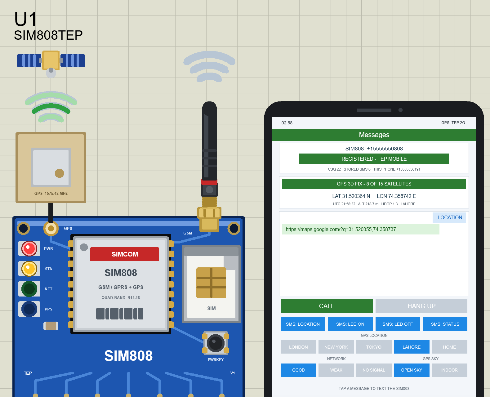
GPS: fix, 8 of 15 satellites | lat 31.520365 | lon 74.358750 | alt 215.888 m | ...Then click SMS: LOCATION. The phone texts the SIM808, the RI pin tells the Arduino (through the INT0 interrupt on D2) that a message has arrived, and a few seconds later the reply appears on the phone as a chat bubble (the first picture of this article shows this moment):
(RI pin went LOW)
SMS from +15555550191: LOCATION
  -> reply: https://maps.google.com/?q=31.520355,74.358737 (sent)
Have a look at the line monitor too (the lower window in the complete-simulation picture above). It shows the SIM808's side of the conversation (the Arduino's commands don't appear, because the monitor only listens to the SIM808's TXD line and the sketch turns the echo off with ATE0). Here is the LOCATION exchange from that picture, taken at HOME (after LAHORE your +CGNSINF line shows the Lahore position instead; the line is shortened):
+CMT: "+15555550191","","26/10/01,04:28:20+20"
LOCATION

+CGNSINF: 1,1,20260930232820.000,51.477882,-0.001496,44.170,0.04,0.0,1,,1.2,2.3,...

OK

>
+CMGS: 1

OK
The +CMT line brings the sender's number and the time stamp (the PC's local time again), and the next line is the text. The +CGNSINF answer is the Arduino reading the GPS, ">" is the prompt for the SMS text, and +CMGS: 1 means the SMS has been sent. Every answer ends with OK.
Tip: The Proteus Virtual Terminal stops scrolling after about a minute of continuous output (its screen buffer is full). Just right-click it and select Clear Screen to continue. The Proteus Simulation Log also lists what the model does: its settings at start, the AT commands with their answers, and the buttons you click (for example GPS location TOKYO). Include it when you ask for help in the comments.
Useful SIM808 AT Commands
| Command | What it does |
|---|---|
| AT | Checks the module. The SIM808 learns your baud rate (serial speed) from the first AT, so always send AT first |
| ATI | Module version, e.g. SIM808 R14.18 |
| AT+CSQ | Signal quality: 0 - 31, 99 = no signal |
| AT+CREG? | Network registration: 0,1 = registered |
| AT+COPS? | Operator name |
| AT+CCLK? | Network time |
| AT+CMGF=1 | SMS text mode |
| AT+CMGS="number" | Sends an SMS (type the text after ">" and end it with Ctrl+Z; in Arduino code: gsm.write(26)) |
| AT+CNMI=2,2,0,0,0 | Shows new SMS directly |
| ATD+number; | Makes a voice call (e.g. ATD+15555550191; calls the virtual phone - don't forget the ;) |
| ATA / ATH | Answers / hangs up a call |
| AT+CGNSPWR=1 | Switches the GPS on |
| AT+CGNSINF | Reads the GPS position (21 fields) |
| AT+CGNSTST=1 | Streams the GPS NMEA sentences on the serial port |
Things to Know Before Using a Real SIM808
The Arduino code is written for a real SIM808 too (it uses only standard SIM808 AT commands), but it has only been tested in the simulation, not on real hardware. Keep these points in mind:
- Power supply: the SIM808 needs 3.4 - 4.4 V (4.0 V typical, 4.5 V absolute maximum) from a supply that can deliver 2 A peaks while it transmits; below 3.0 V it may switch itself off. Never power it from the Arduino's 5 V or 3.3 V pin (in the simulation VCC simply goes to the +5 V terminal; don't copy that to a real board). Use your board's own supply input (a Li-ion cell, or the DC jack and regulator of the bigger development boards; check your board's rating).
- Logic level: the SIM808's serial port uses 2.8 V logic. Use your board's level shifter (set its VIO / VMCU pin or TTL jumper to the Arduino's 5 V), or a voltage divider between the Arduino's D9 and the module's RXD that brings the 5 V signal down to the module's 2.8 V level.
- PWRKEY: it is pulled up inside the module (an internal resistor keeps it HIGH), so only ever pull it LOW, and don't pulse it when the module is already on.
- Network: the SIM808 is a 2G module, so you need a SIM card and a 2G (GSM) network.
- GPS: the GPS antenna needs a clear view of the sky. The data sheet gives about 30 seconds for the first fix (cold start), and there is no fix indoors.
- GPS only: the SIM808 uses the American GPS satellites (plus SBAS correction satellites and Japan's QZSS), not the Russian GLONASS satellites.
Limitations of the Simulation
- The mobile network, the operator "TEP MOBILE" and the phone numbers are simulated. No real SIM card is used and no Google service is contacted: the Maps link is just text (you can open it in your browser).
- The satellites are a simplified set of GPS satellites. Their positions and signals behave realistically, but they are not the real satellites of that day. The module stands still: its position only wanders by a few metres, like a real receiver's.
- The virtual phone is one fixed partner (+15555550191 by default). All TEP SIM808 modules and phones in one design share the same simulated network, so they can text and call each other by number.
- Not simulated: GPRS / internet (TCP, HTTP, FTP, email), Bluetooth, PDU-mode SMS (only text mode, AT+CMGF=1, works), audio and DTMF (keypad tones), the SIM phone book, AT+CNUM, the SIM PIN, sleep modes, the DTR pin, the supply current and brown-outs (short supply dips), SBAS / DGPS corrections and assisted GPS.
So, that was all about the SIM808 Library for Proteus. I hope you will enjoy simulating your GPS tracker projects with it. If you only need GSM or only GPS, have a look at our SIM800L Library for Proteus and NEO-6M GPS Library for Proteus too. If you have any questions or suggestions, please ask in the comments and I will help you out. Till the next tutorial, take care and have fun!