


Project Files of SIM808 Library for Proteus V1.1 (GSM + GPS + Arduino)
 Libraries
 Code
 Projects
 Simulation
sim808-tep-v1-1-125d2a772d484cdbb0f769542167bf4a.zip

SIM808 GSM + GPS Library for Proteus V1.1
SIM808 GSM + GPS Library for Proteus V1.1 comes as a ZIP archive of 23 files (1.5 MB, 3.4 MB unpacked) holding Proteus library files, simulation model DLLs, a Proteus simulation, an Arduino sketch, an Arduino library, compiled HEX firmware and data files.
- LIBProteus library
- IDXProteus library index
- DLLProteus model
- DSNProteus simulation
- INOArduino sketch
- LIBArduino library
- HEXHEX firmware
- CSVData file
Description
This is the download page of SIM808 GSM + GPS Library for Proteus V1.1, the file package of the tutorial SIM808 Library for Proteus V1.1 (GSM + GPS + Arduino), published on The Engineering Projects in October 2026. Here you get the ZIP file (1.5 MB) with the Proteus library files (LIB and IDX), the simulation model (DLL), a ready Proteus simulation, an Arduino sketch, an Arduino library, the compiled HEX firmware and data files, the list of files it contains, the README when there is one, and the installation steps in order.
What this library is
SIM808-GSM-GPS-Library-for-Proteus-v1.1.zip with SIM808 Simple and Advance (TEPSIM808.LIB and TEPSIM808.DLL), the TEP Serial Monitor and Arduino UNO libraries for Proteus, the Arduino GPS tracker simulation with its HEX file, the demo sketch with the AltSoftSerial 1.4 library and a README.
This is version 1.1; older or newer releases, when they exist, are listed in the Development tab.
What is inside the ZIP file
- ArduinoV3TEP.LIB – Proteus library, 95.6 KB
- TEPSERIALMON.LIB – Proteus library, 11.1 KB
- TEPSIM808.LIB – Proteus library, 125.7 KB
- ArduinoV3TEP.IDX – Library index, 830 B
- TEPSERIALMON.DLL – Simulation model, 978 KB
- TEPSIM808.DLL – Simulation model, 542.5 KB
- and 17 more, all listed in the File Structure tab
The archive unpacks to 3.4 MB and carries its own README (README.txt), shown in the README tab above.
How to download
Use the download panel at the top of this page: after the counter (30 seconds for guests, 10 for members) the black button unlocks and the ZIP file comes straight from our content network. If the browser opens it instead of saving, use Save as; extract the whole archive before using anything inside it.
How to install
- Step 1: Extract the ZIP file with Windows (Extract All), 7-Zip or WinRAR, keeping its folders.
- Step 2: Close Proteus and copy ArduinoV3TEP.LIB, TEPSERIALMON.LIB and TEPSIM808.LIB and ArduinoV3TEP.IDX into its LIBRARY folder (Proteus 8: C:\Program Files (x86)\Labcenter Electronics\Proteus 8 Professional\LIBRARY).
- Step 3: Copy TEPSERIALMON.DLL and TEPSIM808.DLL into the MODELS folder next to it, so the part simulates.
- Step 4: Start Proteus, press P and search for "ArduinoV3TEP"; place and wire it as in the tutorial.
- Step 5: In the Arduino IDE use Sketch → Include Library → Add .ZIP Library, then restart the IDE.
- Step 6: Open SIM808_GPS_Tracker.ino, Echo.ino and ReceiveTest.ino in the Arduino IDE, pick board and port and Verify (Export Compiled Binary gives the HEX).
- Step 7: In Proteus set the controller's Program File to SIM808_GPS_Tracker.hex; on hardware, flash the same file.
- Step 8: Open SIM808-GPS-Tracker-ArduinoUnoV3.pdsprj in Proteus and press Play.
Read the detailed guide
This page is for the files. The full tutorial, SIM808 Library for Proteus V1.1 (GSM + GPS + Arduino), explains the circuit and the code step by step and shows the working results and the simulation; read it before you build. Questions about the download or the installation go in the comments below; more Proteus downloads are listed further down this page.

File Structure
 File Structure
4.6 KB9.8 KB968 B1.4 KB8.3 KB2.5 KB82 B441 B422 B1.3 KB384 B19.2 KB830 B95.6 KB11.1 KB125.7 KB978 KB542.5 KB35.5 KB37.9 KB978 KB542.5 KB37.7 KBGallery12 images from the tutorialOpen the tutorial
 Gallery12 images from the tutorial
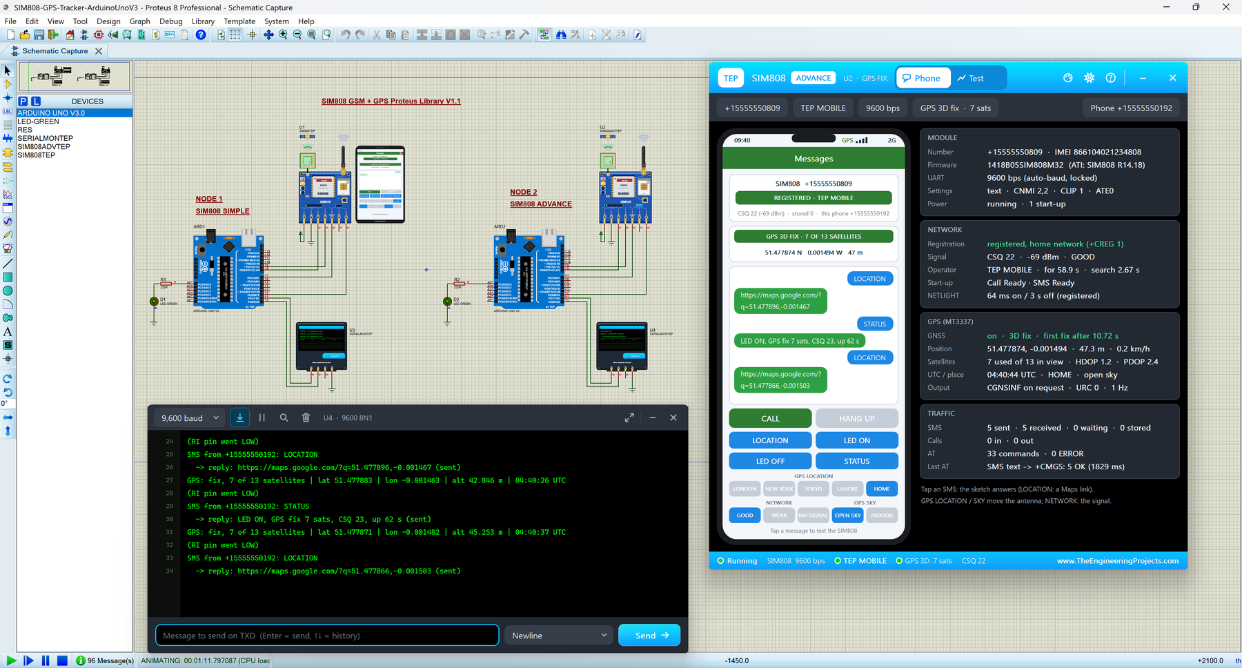
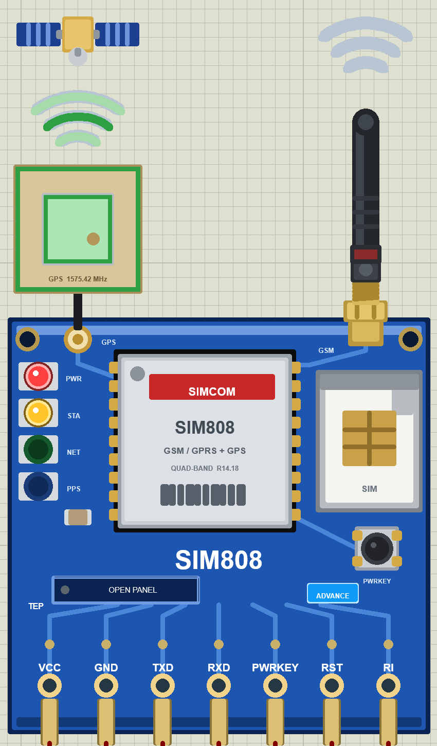
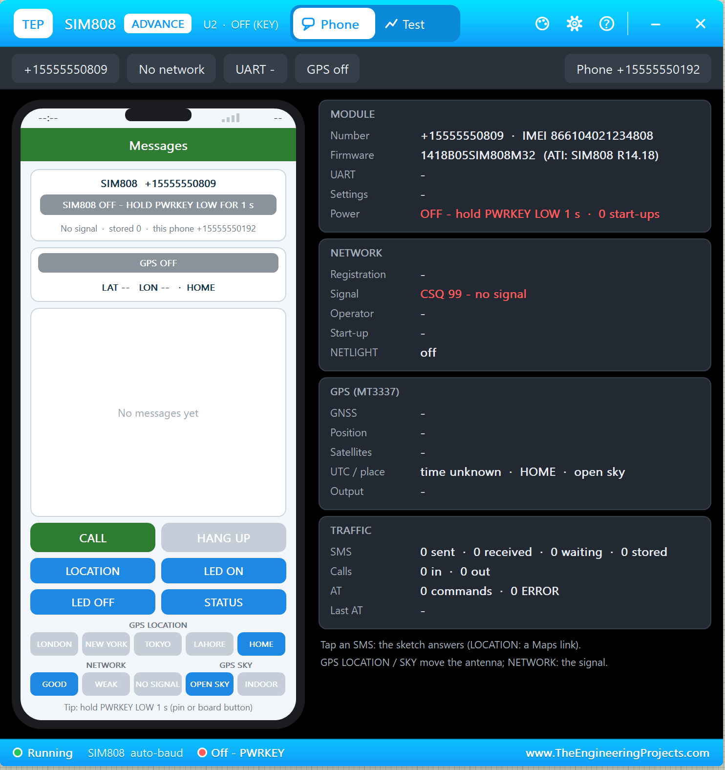
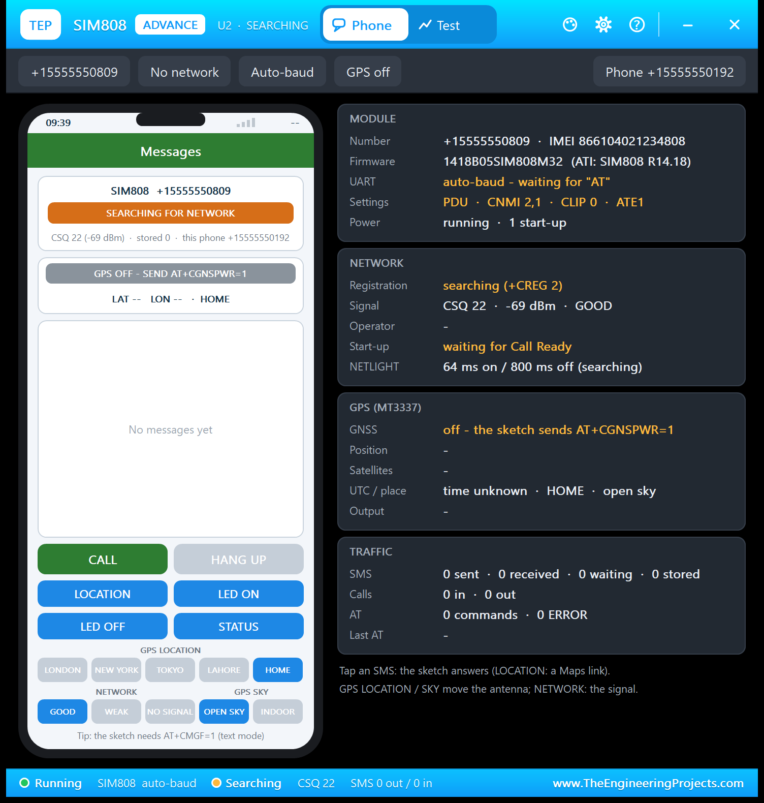
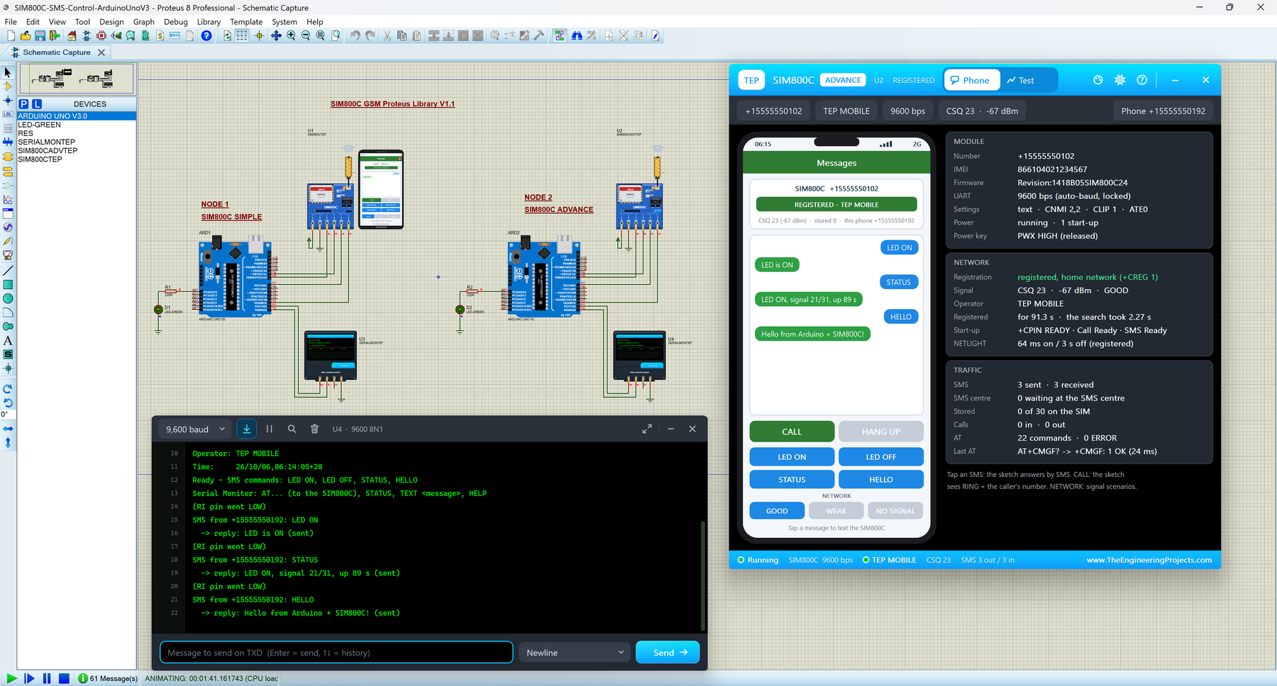
The circuit, the board and the results as they appear in SIM808 Library for Proteus V1.1 (GSM + GPS + Arduino). Open an image for its full size.
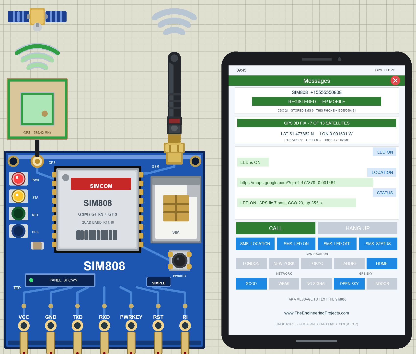
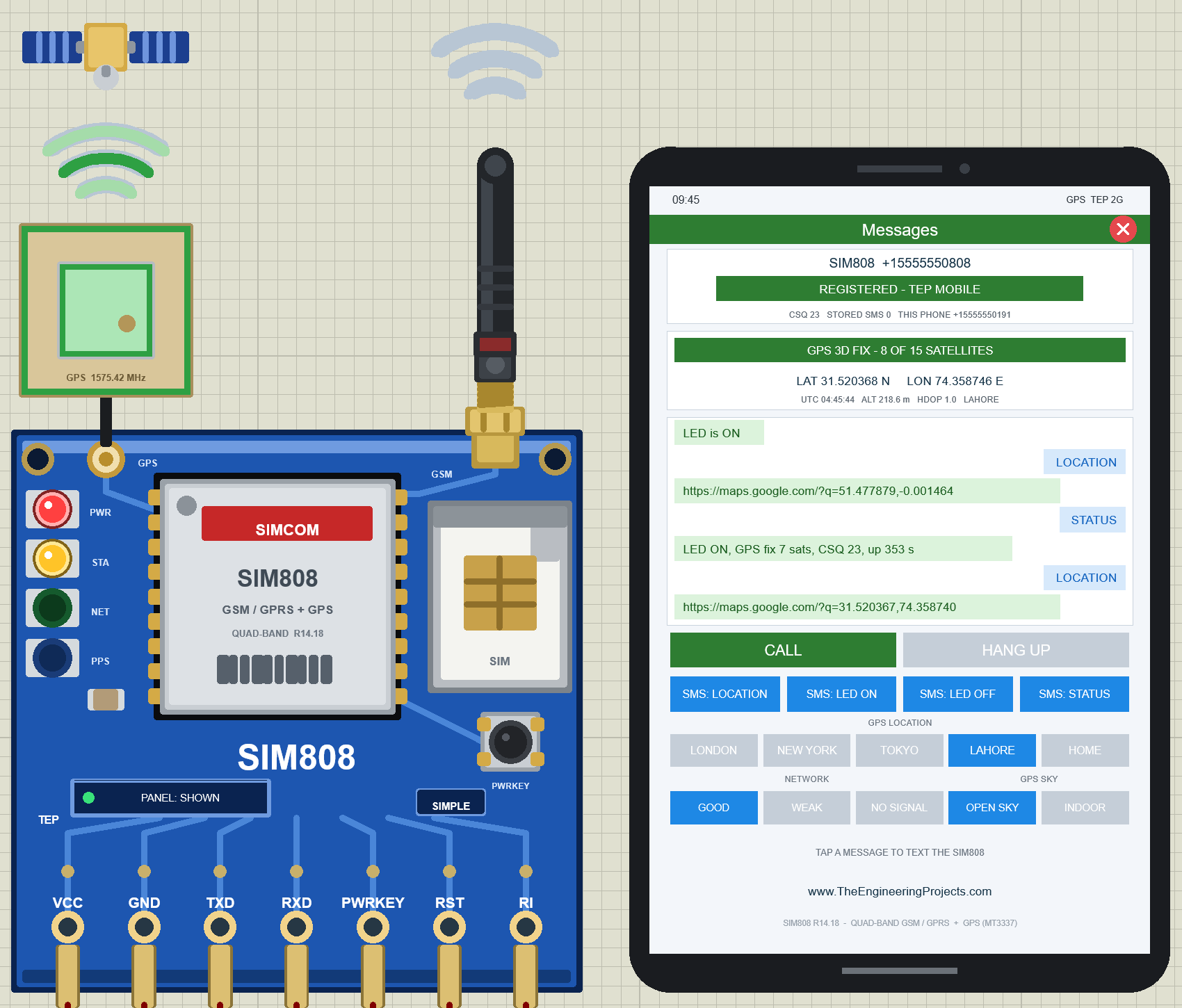
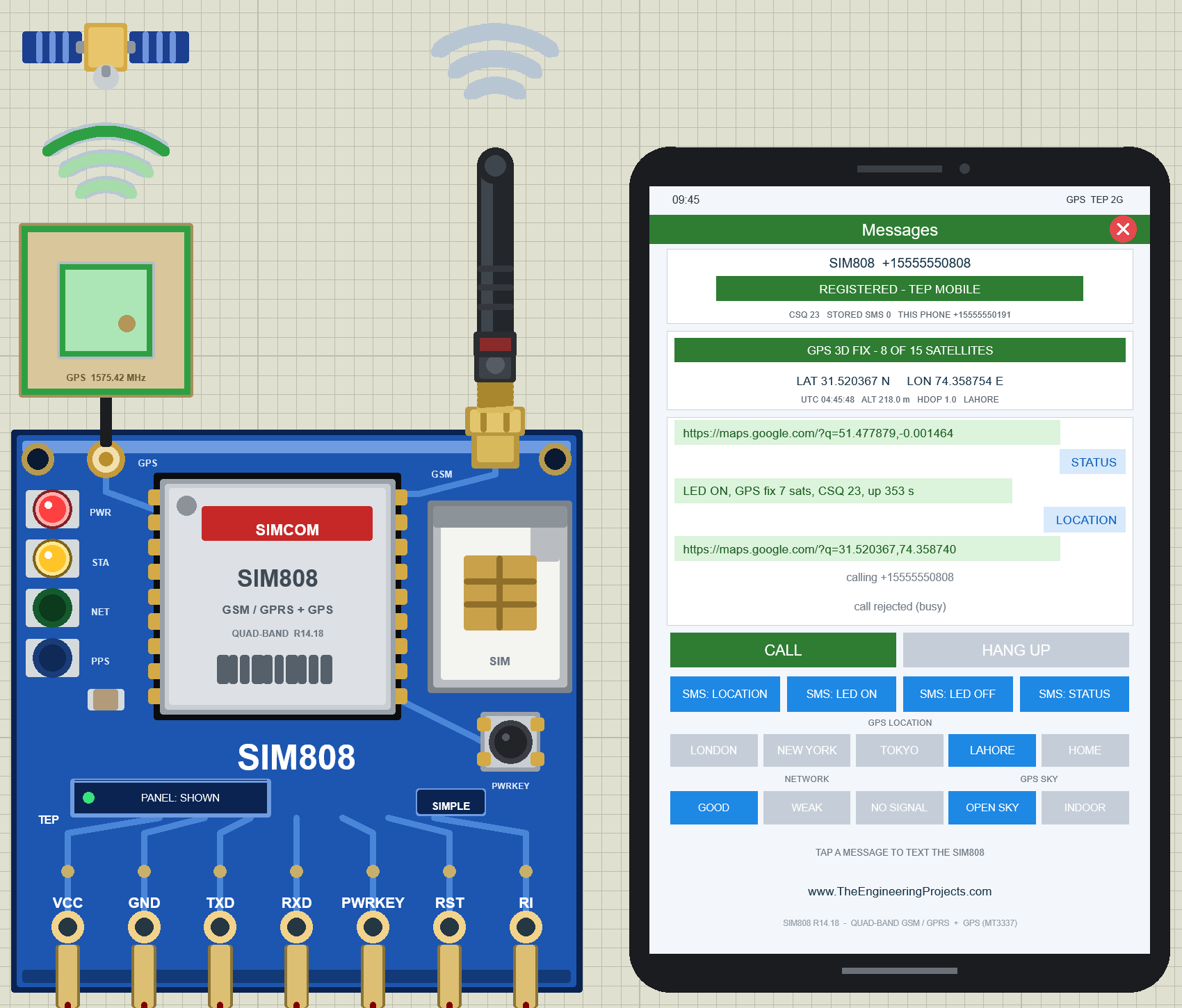
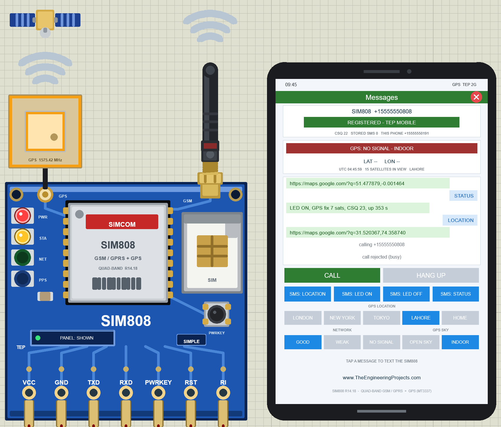
README
 README
SIM808 GSM / GPRS + GPS MODULE (SIMCom SIM808 breakout) LIBRARY FOR PROTEUS - V1.1
Designed by The Engineering Projects
www.TheEngineeringProjects.com

IMPORTANT LINKS
Article (read it first - pictures, step by step, every feature explained):
  https://www.theengineeringprojects.com/2026/10/sim808-library-for-proteus.html
Report a bug or suggest a feature (our forum):
  https://www.theengineeringprojects.com/forum/category/sim808-proteus-library
The demo uses our TEP Serial Monitor Advance (included) instead of Proteus's
Virtual Terminal - its own article:
  https://www.theengineeringprojects.com/2026/10/serial-monitor-advance-proteus-library.html
Support us (the libraries are free):
  https://www.theengineeringprojects.com/donate

FILE STRUCTURE
SIM808-TEP-v1.1/
|-- Proteus Library Files/
|   |-- ArduinoV3TEP.IDX                              0.8 KB   its index -> LIBRARY folder
|   |-- ArduinoV3TEP.LIB                             95.6 KB   TEP Arduino UNO (demo) -> LIBRARY folder
|   |-- TEPSERIALMON.LIB                             11.1 KB   TEP Serial Monitor Advance -> LIBRARY folder
|   |-- TEPSIM808.LIB                               125.7 KB   SIM808 Simple + Advance (2 devices) -> LIBRARY folder
|-- Proteus Model Files/
|   |-- TEPSERIALMON.DLL                            978.0 KB   Serial Monitor model -> MODELS folder
|   |-- TEPSIM808.DLL                               542.5 KB   SIM808 model -> MODELS folder
|-- Proteus Simulation/
|   |-- SIM808_GPS_Tracker.hex                       37.9 KB   both UNOs (GPS tracker v1.1)
|   |-- SIM808-GPS-Tracker-ArduinoUnoV3.pdsprj       35.5 KB   demo: UNO 1 + SIM808 Simple, UNO 2 + Advance
|   |-- TEPSERIALMON.DLL                            978.0 KB   copy of the monitor model
|   |-- TEPSIM808.DLL                               542.5 KB   copy of the model so the demo runs as is
|-- Arduino Code/
|   |-- SIM808_GPS_Tracker/SIM808_GPS_Tracker.ino    19.2 KB   sketch (source of the .hex)
|   |-- libraries/AltSoftSerial/                     30.1 KB   AltSoftSerial 1.4 (MIT, LICENSE.txt), 11 files
|-- README.txt                                      ~38.6 KB   this file
Total: 3.36 MB (unzipped). The C++ source code of the model is not included.

WHAT IS IT?
A simulation model of the SIMCom SIM808 GSM / GPRS + GPS module on a generic
blue breakout board for Proteus 8. It talks to your Arduino like the real one:
the module stays OFF after power-up until its PWRKEY pin is held LOW for more
than 1 s, then it learns the baud rate from the first "AT" (auto-bauding),
sends Call Ready and SMS Ready, registers to the network and answers the AT
commands for SMS (text mode), calls, the network and the GPS (AT+CGNSPWR,
AT+CGNSINF, the NMEA stream, PMTK commands). The GPS engine (the MT3337 inside
the SIM808) sees a simulated sky from the place you choose and gets its first
fix like a real receiver. Next to the module there is a virtual smartphone with
its own number and a GPS strip: it texts the module, calls it, answers its
calls and shows the SMS it receives as chat bubbles - text LOCATION and the
demo sketch answers with a Google Maps link. Every TEP SIM808 and every virtual
phone in a design share one simulated network, so modules can also text and
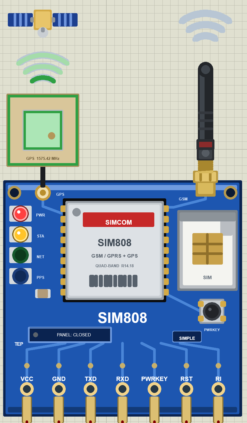
call each other. The part looks like the blue breakout with the silver SIM808,
the SIM holder, the PWRKEY button, the rubber-duck GSM antenna and the GPS
ceramic patch. While the simulation runs the PWR / STA / NET / PPS LEDs show
the supply, the module's STATUS, the NETLIGHT blink and the GPS's 1PPS pulse; a
ring LED round the GSM antenna and the lamp in its tip light orange while the
module sends and green while it receives, the waves above it ripple out
(sending) or in (receiving), and the GPS patch glows amber while the GPS
acquires and green once it has a fix.

TWO DEVICES IN ONE LIBRARY (search "SIM808", "GSM" or "GPS" in Pick Devices):
  SIM808 Simple    device SIM808TEP     "SIM808 GSM / GPRS + GPS Module (SIMCom) - Simple"
                   On-Sheet Panel: the virtual phone with its GPS strip is drawn
                   on the schematic next to the module (the v1.0 phone) - click
                   its CALL, HANG UP, SMS, GPS LOCATION, NETWORK and GPS SKY
                   buttons. The red X in the phone's app bar closes it, the
                   PANEL button on the board opens it again. Your v1.0 designs
                   keep working with this device.
  SIM808 Advance   device SIM808ADVTEP  "SIM808 GSM / GPRS + GPS Module (SIMCom) - Advance"
                   Pop-Up Panel: only the module board on the schematic; at Run
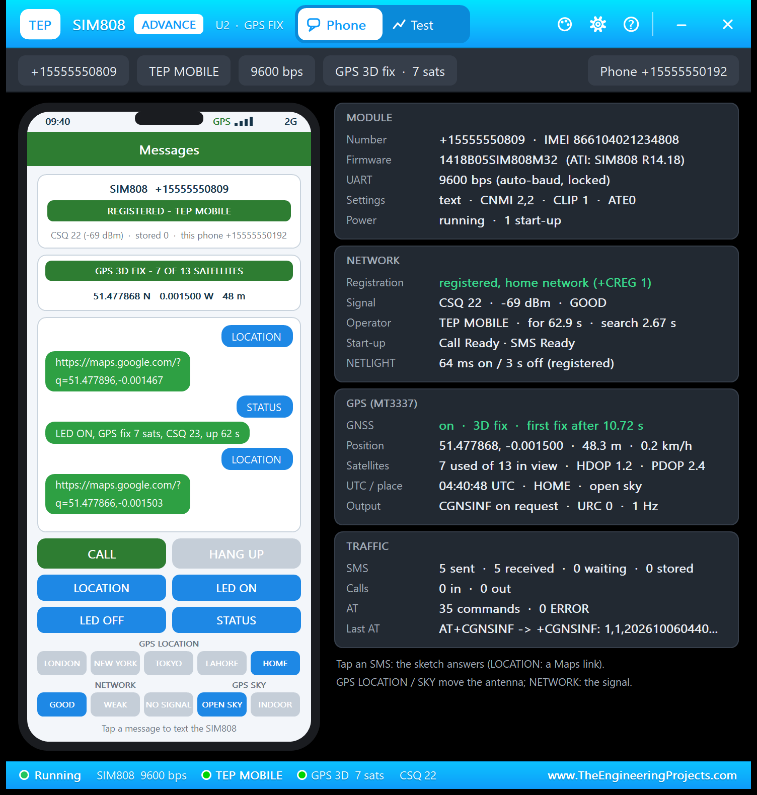
                   a TEP pop-up window opens - the same look as the TEP Serial
                   Monitor (move it by its header, resize it, minimise it). The
                   tabs Phone and Test sit in the header; the gear and ? icons
                   open Settings and Help; the palette icon switches the theme:
                     Phone     the virtual phone redrawn for the window (signal
                               bars, GPS strip, chat bubbles, call bar, CALL /
                               ANSWER, HANG UP, the four SMS, GPS LOCATION,
                               NETWORK, GPS SKY) beside four cards: MODULE
                               (number, IMEI, firmware, UART speed, the settings
                               your sketch made, power and start-ups), NETWORK
                               (registration, CSQ and dBm, operator, how long it
                               is registered and how long the search took, the
                               start-up messages, the NETLIGHT pattern), GPS
                               (power, fix and the first-fix time, position,
                               satellites used / in view, HDOP / PDOP, UTC, the
                               place and sky, the output - CGNSINF, URC, NMEA)
                               and TRAFFIC (SMS sent / received / waiting at the
                               SMS centre / stored, calls, AT commands and
                               errors, the last AT command with its reply and
                               response time)
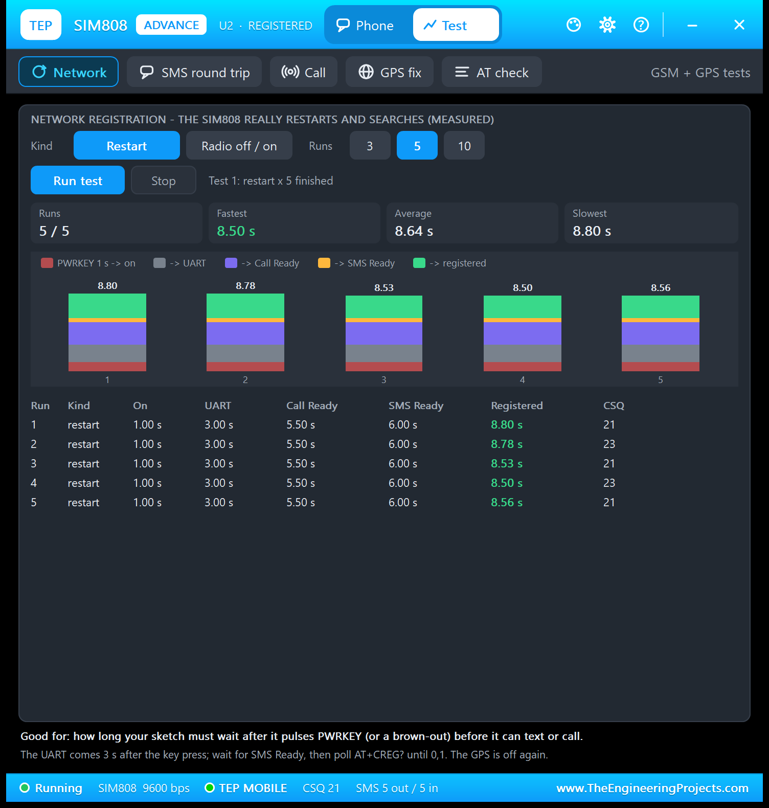
                     Test      five test tools, all measured on the model:
                               Network, SMS round trip, Call, GPS fix and AT
                               check (see THE TEST TOOLS below)
                     Settings  theme (TEP Dark / Light), text size, open at Run,
                               window size - remembered for your Windows user
                     Help      Help & Support like the TEP Serial Monitor: report
                               a bug, suggest a feature, article, user guide,
                               updates, donate, website, forum; Copy diagnostics
                               (module, network, GPS, traffic, test results) for
                               a bug report
                   The OPEN PANEL button on the board opens the window again
                   after you close it.
Both devices use the same model (TEPSIM808.DLL) and the same properties.

NEW IN V1.1
* Two devices: SIM808 Simple (phone on the sheet, close / open) and SIM808
  Advance (pop-up window with the phone, five test tools, settings and help) -
  see above. The Advance device has its own default numbers (+15555550809 /
  phone +15555550192), so a Simple and an Advance module in one design stay
  distinct.
* Board: a ring LED round the GSM antenna and a lamp in its tip (orange =
  sending, green = receiving), the GPS patch glows (amber = acquiring, green =
  fix, off while the GPS is off), a PANEL / OPEN PANEL button and a SIMPLE /
  ADVANCE badge; the title moved up so the button never covers it. The LEDs
  keep their v1.0 colours (PWR red, STA amber, NET green, PPS blue).
* Model (GSM, as in the TEP SIM800L / SIM800C v1.1): the network search now
  takes 2.2 - 3.2 s (weak signal 2.8 - 3.4 s, v1.0: always 3 s); every SMS
  takes its own time on the network, like on a real one: 1.2 - 1.9 s from the
  phone to the module and 1.7 - 2.5 s from the module to the phone (v1.0:
  always 1.5 s and 2 s; with a weak signal 2.5 x as long); AT+CFUN=1 after
  AT+CFUN=0 reports +CREG: 2 (searching); AT+CFUN=1,1 answers OK completely
  before it restarts (v1.0 restarted 50 ms later, which cut the OK at slow
  baud rates); the phone shows 60 characters per message line (v1.0: 56);
  every module event reaches the Simulation Log (v1.0 could skip one when two
  happened at once).
* Model (GPS): a warm start (AT+CGNSCMD=0,"$PMTK102*31" or AT+CGPSRST=2) keeps
  the time and needs 28 / 30 of the cold-start time, as in the SIM808 data
  sheet (cold 30 s, warm 28 s, hot 1 s); v1.0 treated a warm start as a cold
  one.
* The demo uses the TEP Serial Monitor Advance instead of Virtual Terminals -
  one monitor per Arduino (U3 = UNO 1, U4 = UNO 2) with quick buttons - and
  shows both styles: UNO 1 with SIM808 Simple, UNO 2 with SIM808 Advance, an
  LED on A0 of each UNO.
* The demo sketch (v1.1) also takes commands from the Serial Monitor (AT lines
  go to the SIM808 and its answer is printed, STATUS, LOCATION, TEXT
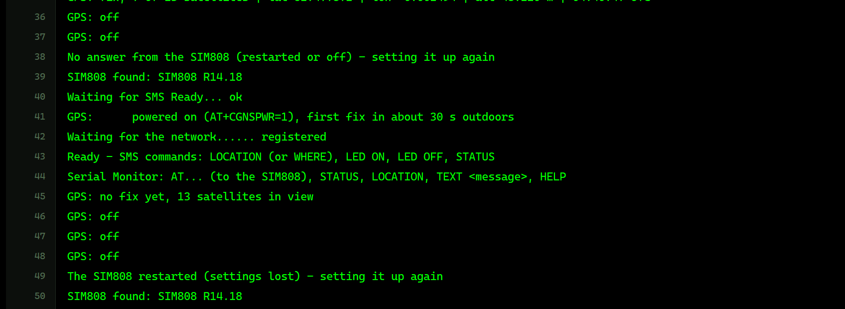
  <message>, HELP), and every 30 s it checks the module: after a restart (the
  module then forgets its settings and switches its GPS off) it sets the
  SIM808 up again, and if the module is OFF (a power-down) it switches it on
  with PWRKEY first.
* README: the 2.8 V divider is now 10 k / 12 k (about 2.7 V). The v1.0 README
  said 10 k / 20 k - that gives 3.3 V, too much for the 2.8 V serial port.
* Version 1.1 everywhere; the C++ source code is no longer included (and
  neither is TinyGPS++, which only the PC tests use).

TEST STATUS
v1.0 was tested in Proteus 8.5 SP0 (1 Oct 2026) with the v1.0 demo (one UNO):
the sketch switched the SIM808 on with PWRKEY, registered (CSQ 22, TEP MOBILE),
switched the GPS on and got a fix at HOME (9 of 13 satellites), then LAHORE +
SMS LOCATION from the phone -> the reply "https://maps.google.com/?q=31.520355,
74.358737" appeared on the phone (the RI interrupt fired).
v1.1 was tested in Proteus 8.5 SP0 (6 Oct 2026) with this package's demo: both
Serial Monitors and the Advance pop-up open at Run (no system caption row);
both sketches switch their SIM808 on with PWRKEY, register (TEP MOBILE), power
the GPS and get a fix (7 of 13 satellites at HOME). U1 (Simple): SMS LOCATION
(Google Maps link), LED ON (D1 lights), STATUS, LAHORE + LOCATION (8 of 15
satellites, 31.52 N 74.36 E), CALL (rejected with ATH), INDOOR (no fix, the
patch turns amber) and OPEN SKY, the red X and PANEL; the Serial Monitor
commands LOCATION and AT+CGNSINF. U2 (Advance): Test > Network restart x 5
(8.50 - 8.80 s; the sketch set the module and the GPS up again), SMS round trip
LOCATION x 5 (3.50 - 4.63 s, 5 / 5 Maps links, 1.2 m off on average), Call x 3
(first RING 2.00 s, rejected 0.05 s later), GPS fix cold x 5 (10.26 - 10.89 s)
and hot x 5 (1.26 - 1.89 s), AT check, Settings, Help, close and OPEN PANEL.
PC tests: 1455 automatic checks on a PC: 278 on the module model at the pin
level (the 217 of v1.0: power keys, auto-bauding, identity strings, SMS, calls,
RI, CGNSINF, the NMEA stream read by the unmodified TinyGPS++, PMTK commands,
indoor / open sky ... - one v1.0 check changed on purpose: the RI pulse of an
SMS now comes at the SMS's own network time - plus the v1.1 network spread,
SMS times, AT+CFUN, warm start, AT log and the five test tools with their
measured times); 52 with the real demo sketch running against the model (the
29 of v1.0 plus the Serial Monitor commands, the pop-up's tools with the real
sketch, setting the module up again after a restart and switching it on again
after a power-down); 210 on the complete Proteus model (the 79 of v1.0 plus
both devices, the ring LED / tip lamp / patch glow, the phone close / open, a
v1.0 design, the pop-up window, its pages and buttons, the five test tools);
915 on the rendered pop-up windows (every page fits in TEP Dark and Light, at
Large text and 150 % DPI; every tool's hint lines fit the window).

INSTALLATION (about 2 minutes)
1. Close Proteus. Extract the WHOLE ZIP to a normal folder (e.g. Desktop).
2. Copy everything in "Proteus Library Files" (TEPSIM808.LIB with both devices,
   TEPSERIALMON.LIB and the TEP Arduino UNO V3 library ArduinoV3TEP.LIB / .IDX
   used by the demo) to the LIBRARY folder of Proteus, for example:
     C:\Program Files (x86)\Labcenter Electronics\Proteus 8 Professional\LIBRARY
   (on some PCs: C:\ProgramData\Labcenter Electronics\Proteus 8 Professional\
   LIBRARY - use the folder that already holds Proteus's own .LIB files).
3. Copy TEPSIM808.DLL and TEPSERIALMON.DLL from "Proteus Model Files" to the
   MODELS folder (...\Proteus 8 Professional\MODELS).
4. Updating from v1.0: replace TEPSIM808.LIB (delete any TEPSIM808.IDX) and
   TEPSIM808.DLL. A v1.0 design keeps its v1.0 symbol: it runs with the new
   model (without the v1.1 board parts and the red X) - re-pick the part to get
   the v1.1 symbol.
5. Start Proteus. In Pick Devices (P) search "SIM808": you get the Simple and
   the Advance device (category Peripherals > Wireless).

RUN THE DEMO
"Proteus Simulation\SIM808-GPS-Tracker-ArduinoUnoV3.pdsprj" - keep the .hex file
and the two DLLs beside the project. Both UNOs run SIM808_GPS_Tracker.hex.
  UNO 1 (ARD1): SIM808 Simple (U1, number +15555550808, its phone on the sheet
  +15555550191) and Serial Monitor U3. UNO 2 (ARD2): SIM808 Advance (U2,
  +15555550809, its phone in the pop-up window +15555550192) and Serial Monitor
  U4. An LED (D1 / D2) on A0 of each UNO.
  1. Press Run. Both monitor windows open (9600 baud) and so does U2's pop-up.
     The SIM808s start OFF (the phones say SIM808 OFF - HOLD PWRKEY LOW FOR
     1 s); the monitors show "Looking for the SIM808... no answer (it starts
     switched OFF)", "Switching the SIM808 on: PWRKEY LOW for 1.2 s", "SIM808
     found: SIM808 R14.18", "Waiting for SMS Ready... ok", the GPS switched
     on, the network, the signal, the operator and the network time, then the
     command list (about 12 s of simulation time). The GPS lines follow every
     10 s; the first fix comes about 10 s after the GPS was switched on
     (GPSTTFF; a real module needs about 30 s outdoors).
  2. U1: tap "SMS: LOCATION" on the phone beside the module - U3 prints the SMS
     and the reply, and a Google Maps link appears on the phone. Try LED ON
     (LED D1 lights), STATUS, CALL (the sketch shows the caller's number and
     rejects the call), the GPS LOCATION buttons (LAHORE, TOKYO ...) and then
     LOCATION again, INDOOR (no fix), NO SIGNAL (an SMS waits at the SMS
     centre until GOOD). Close the phone with its red X and open it with PANEL
     on the board.
  3. U3 / U4 quick buttons: AT+CSQ, AT+CGNSINF (sent to the SIM808, its answer
     is printed), STATUS, LOCATION (the Maps link on the monitor). Type your
     own AT commands too, or TEXT <message> (an SMS to the last number that
     texted the module - text it first).
  4. U2 (Advance): the same phone is on its Phone page, with the MODULE /
     NETWORK / GPS / TRAFFIC cards. Open the Test tab:
       Network: Restart, 5 runs, Run test - the module is switched off and on
         with its power key five times (watch U4: within 30 s the sketch
         notices and sets it up again, the GPS too); then Radio off / on.
       SMS round trip: LOCATION, 5 runs - about 4 - 5 s per answer, each a
         Google Maps link a few metres from the true position.
       Call: 3 calls - the sketch rejects each a fraction of a second after the
         first RING (its RI interrupt prints "(RI pin went LOW)" on U4).
       GPS fix: Cold, 5 runs - about 10 - 11 s each (GPSTTFF 10); Hot - about
         1 - 2 s.
       AT check: the module's settings and the sketch's last AT commands.
  5. Close U2's window and open it again with OPEN PANEL on the board.
Closed a monitor window? Click OPEN MONITOR on the monitor part.

WIRING (AltSoftSerial, the same on both UNOs)
  SIM808 VCC -> supply, GND -> GND, TXD -> D8, RXD <- D9 (AltSoftSerial's fixed
  UNO pins), PWRKEY <- D7, RI -> D2 (INT0), RST left open (internal pull-up).
  LED + 220 ohm from A0 to GND.
  The sketch pulls PWRKEY LOW for 1.2 s (D7 as an OUTPUT LOW), then releases it
  as an INPUT (the module pulls PWRKEY up) - never drive PWRKEY HIGH from a 5 V
  pin.
  Serial Monitor RXD <- Arduino D1 (TX), Serial Monitor TXD -> Arduino D0 (RX),
  Serial Monitor GND -> ground. RXD2 is not used in this demo: the TXD -> D8
  line lies between the D9 -> RXD and D7 -> PWRKEY wires, so a wire to it would
  cross one of them (or loop round the whole UNO) - the sketch prints the
  module's answers itself ("  < ..."). Wire RXD2 to the module's TXD in your
  own design to watch the raw AT traffic and NMEA.
  Serial.begin(9600) in the sketch.
In the sketch: AltSoftSerial gsm;   gsm.begin(9600);
Pin order in Proteus: VCC GND TXD RXD PWRKEY RST RI - the signals a SIM808
breakout gives you; the header order on real boards differs from board to
board.
REAL HARDWARE:
 * The SIM808 itself needs 3.4 - 4.4 V (4.0 V typical, 4.5 V absolute
   maximum) and draws up to 2 A peaks in its transmit bursts; it may switch
   off below 3.0 V. Never feed it from the Arduino's 5 V or 3.3 V pin - use
   your board's own supply input (a Li-ion cell, or the DC jack and regulator
   of the larger boards; check your board's rating) with a common GND.
 * The module's serial port is 2.8 V logic: use the board's level shifter (its
   VIO / VMCU pin or TTL jumper set to the Arduino's 5 V) or put a divider
   between the Arduino's D9 and RXD - 10 k from D9 to RXD and 12 k from RXD to
   GND gives about 2.7 V. (The v1.0 README said 10 k / 20 k: that gives about
   3.3 V - too high for the 2.8 V port.)
 * PWRKEY is pulled up inside the module: only ever pull it LOW.
 * 2G only: the SIM808 is a quad-band GSM / GPRS module (850 / 900 / 1800 /
   1900 MHz) and needs a SIM card; it does not work where the 2G network has
   been switched off.
 * The GPS needs its antenna with a view of the sky: the data sheet gives a
   first fix in 30 s (cold start), and there is none indoors.

WHY AltSoftSerial AND NOT SoftwareSerial
SoftwareSerial can send but cannot RECEIVE in Proteus 8.5: it needs pin-change
interrupts, which the Proteus 8.5 ATmega328P model never runs. AltSoftSerial
(Paul Stoffregen, MIT licence) uses Timer1 and works in Proteus and on real
boards. Don't use D10 while it runs (digitalRead / digitalWrite on D10 disturbs
its Timer1 output). The external interrupts INT0 / INT1 (D2 / D3) do work, so
the RI pin goes to D2. Your own SoftwareSerial sketches will show the module
working on its phone but the Arduino receiving nothing - use AltSoftSerial,
the hardware Serial port or an Arduino Mega (Serial1-3).

WHAT THE MODULE DOES
Power: with POWERON = KEY (default) the module is OFF when VCC comes up, like a
  bare SIM808. PWRKEY LOW for more than 1 s switches it on; the serial port and
  STATUS come up 3 s after PWRKEY went low. PWRKEY LOW for 1 s while it runs:
  "NORMAL POWER DOWN", STATUS low 2 s after PWRKEY went low. AT+CPOWD=1 does the
  same, AT+CFUN=1,1 answers OK and restarts. RST LOW for at least 105 ms resets
  the module (STATUS back 2.7 s after RST is released). POWERON = AUTO is for
  boards that switch the module on by themselves. The board's PWRKEY button
  can be clicked: it holds PWRKEY low for 1.5 s.
Auto-bauding: the module is silent until it receives "AT" (any speed from 1200
  to 115200 bps), then answers at that speed. "Call Ready" and "SMS Ready"
  follow 2.5 s and 3 s after the serial port is ready; with a fixed speed
  (AT+IPR=9600) RDY, +CFUN: 1 and +CPIN: READY are sent first. Every new
  simulation run starts from the factory settings.
Network: "searching" (+CREG: 0,2) until registered (+CREG: 0,1) to OPERATOR,
  2.2 - 3.2 s after SMS Ready (a repeatable spread per SIM number). Signal:
  GOOD = CSQ 21-23, WEAK = CSQ 7-9 (SMS take 2.5 x as long), NO SIGNAL = +CSQ:
  99,99, not registered, calls drop. AT+CFUN=0 switches the radio off, AT+CFUN=1
  searches again (+CREG: 2).
SMS: text mode, the "> " prompt, Ctrl-Z sends, ESC cancels; +CMGS: n comes
  after delivery (1.7 - 2.5 s after Ctrl-Z). An SMS from the phone reaches the
  module after 1.2 - 1.9 s. Every SMS gets its own time, like on a real
  network. SMS sent to a module that is off or not registered wait at the "SMS
  centre" and are delivered when it registers.
Calls: RING every 3 s, each followed by +CLIP: "+number",145,"",0,"",0 after
  AT+CLIP=1. ATA answers, ATH rejects (the caller sees BUSY); an unanswered
  call ends after 30 s.
GPS (the MT3337 GPS engine inside the SIM808: GPS + QZSS + SBAS, no GLONASS):
  off at power-up. AT+CGNSPWR=1 starts it; the first fix follows after GPSTTFF
  (10 s by default to keep demos short; the data sheet gives 30 s cold, 28 s
  warm and 1 s hot start). Switching the GPS off and on again keeps the time and
  the satellites (hot start); a power-down or a reset makes the next start a
  cold start (no backup battery). AT+CGNSINF answers the 21-field position
  line; AT+CGNSTST=1 streams GGA GLL GSA GSV RMC VTG once a second on the same
  TXD pin, at the AT port's speed. A simplified constellation (30 GPS
  satellites, QZSS 193 and seven SBAS satellites) seen from the chosen place at
  the simulated UTC time: realistic in kind, not the real satellites of that
  day. The position wanders by a few metres like a real receiver's; INDOOR
  makes every signal 40 dB weaker: no fix.
LEDs: PWR (red) = supply, STA (amber) = STATUS (module on), NET (green) =
  NETLIGHT (64 ms on / 800 ms off while searching, 64 ms / 3 s registered),
  PPS (blue) = the 1PPS output, a 100 ms flash each second with a fix.
RI pin: HIGH normally, LOW while an incoming call rings, a 120 ms LOW pulse for
  each new SMS; floating while the module is off.
The network is shared: every TEP SIM808 and every virtual phone in the design
can text and call the others by number (SIMNUM / PHONENUM).

THE PHONE (both devices)
Status bar with the network time ("GPS" while the GPS is on) and "TEP 2G"; a
card with the module's number and state (NO POWER - CHECK VCC / GND, IN RESET
(RST PIN LOW), SIM808 OFF - HOLD PWRKEY LOW FOR 1 s, STARTING..., NORMAL POWER
DOWN, SEARCHING FOR NETWORK, NO SIGNAL, RADIO OFF (AT+CFUN=0), REGISTERED -
operator), CSQ, stored SMS and the phone's own number; a GPS strip (GPS OFF -
SEND AT+CGNSPWR=1, GPS: SEARCHING FOR SATELLITES, GPS ACQUIRING - FIX IN ABOUT
n s, GPS: NO SIGNAL - INDOOR, GPS: NO FIX - n SATELLITES TRACKED, GPS 3D FIX -
n OF m SATELLITES, with latitude, longitude, UTC, altitude, HDOP and the
place); the conversation as chat bubbles (blue = sent by
the phone, green = received from the module) with call events; during a call
a bar shows INCOMING CALL / CALLING / IN CALL mm:ss. A tip line helps (PWRKEY,
AT+CMGF=1, AT+CGNSPWR=1).
Buttons:
  CALL / ANSWER   calls the SIM808 (the module shows RING + +CLIP), or answers
                  a call from the module (ATD<phone number>;)
  HANG UP         ends / rejects the call (the module gets NO CARRIER)
  SMS: LOCATION, SMS: LED ON, SMS: LED OFF, SMS: STATUS
                  text the SIM808 (delivered after 1.2 - 1.9 s)
  GPS LOCATION    LONDON, NEW YORK, TOKYO, LAHORE, HOME (GPSLAT / GPSLON /
                  GPSALT; default the Greenwich observatory)
  NETWORK         GOOD / WEAK / NO SIGNAL
  GPS SKY         OPEN SKY / INDOOR
Board: the LEDs as above; the GSM antenna's ring LED and tip lamp orange while
the module sends (SMS, call set-up), green while it receives, both in turn
during a call, the waves follow them; the GPS patch amber while acquiring,
green with a fix, off while the GPS is off.

THE TEST TOOLS (SIM808 Advance, Test tab) - what they really do
Every tool runs on the live model with your sketch and shows one "Good for:"
line plus one line on how it measures.
  Network   Restart: the tool switches the module off at once (like
            AT+CPOWD=0) and on again with its power key (PWRKEY LOW for 1 s,
            nothing is sent on TXD for it); each step is timed from the key
            press: on 1.0 s, UART 3.0 s, Call Ready 5.5 s, SMS Ready 6.0 s,
…Development1 release
 Development1 release
-
V1.1SIM808 GSM + GPS Library for Proteus V1.1this page
V1.1 is the only release in the Download Center so far. When a newer version is published, it appears above with its own download page.
Installation10 steps
 Installation10 steps
From the download to a working project, in order. The steps follow what the package contains.
You will need
- Proteus Design SuiteProteus 8 or newer (Labcenter), on Windows
- Arduino IDE1.8 or 2.x, with the board of the tutorial chosen under Tools → Board
- Any archive toolWindows, macOS and Linux extract ZIP files on their own
Steps
- 1
Extract the archive
Right-click sim808-tep-v1-1-125d2a772d484cdbb0f769542167bf4a.zip and choose Extract All (or open it with 7-Zip or WinRAR) into a folder you can find again. Keep its folder structure (SIM808-TEP-v1.1) as it is.
- 2
Copy the library files into Proteus
Move ArduinoV3TEP.LIB, TEPSERIALMON.LIB and TEPSIM808.LIB and ArduinoV3TEP.IDX into the LIBRARY folder of your Proteus installation: C:\Program Files (x86)\Labcenter Electronics\Proteus 8 Professional\LIBRARY for Proteus 8, or the matching Proteus 7 folder. Older versions keep it under ProgramData\Labcenter Electronics. If Proteus is open, close it first.
- 3
Add the simulation model
Copy TEPSERIALMON.DLL and TEPSIM808.DLL into the MODELS folder next to LIBRARY, so the component can run, not only be drawn.
- 4
Restart Proteus and place the component
Start Proteus, open a schematic, press P (Pick Devices) and search for the component by the name used in the tutorial. It appears with its pins ready to wire.
- 5
Install the Arduino library
In the Arduino IDE choose Sketch → Include Library → Add .ZIP Library and pick the library, or copy its folder into Documents\Arduino\libraries. Restart the IDE to see its examples.
- 6
Open the sketch in the Arduino IDE
Open SIM808_GPS_Tracker.ino, Echo.ino and ReceiveTest.ino, select your board and port under Tools, then Verify. Sketch → Export Compiled Binary writes the HEX file a simulation needs.
- 7
Load the HEX file
In Proteus double-click the microcontroller, set Program File to SIM808_GPS_Tracker.hex and run the simulation. For real hardware, flash the same file with your programmer.
- 8
Open the example simulation
Open SIM808-GPS-Tracker-ArduinoUnoV3.pdsprj in Proteus to see the wiring exactly as in the tutorial. Check the controller's Program File path, then press Play.
- 9
Use the data files
library.json hold the readings or settings the project uses; open them with Excel, a text editor or the script of the tutorial.
- 10
Follow the tutorial
SIM808 Library for Proteus V1.1 (GSM + GPS + Arduino) explains every connection and setting in order; keep it open beside the files while you build.
FAQs9 questionsContact TEP
 FAQs9 questions
How do I download SIM808 GSM + GPS Library for Proteus V1.1?
Wait for the 30-second guest countdown on this page, then press the download button; the file comes straight from our storage. Members who are logged in skip the wait. If the browser opens the file instead of saving it, use its Save as option. The download link is made for you when the countdown ends and works for 15 minutes; a saved or shared link stops working, so share this page instead.
What is inside the archive?
SIM808 GSM + GPS Library for Proteus V1.1 comes as a ZIP archive of 23 files (1.5 MB, 3.4 MB unpacked) holding Proteus library files, simulation model DLLs, a Proteus simulation, an Arduino sketch, an Arduino library, compiled HEX firmware and data files. Open the File Structure tab for the full list of 23 files.
What should I do if the download does not start?
Check the browser's download list first; an ad blocker or a company firewall can also hold it back, so try another browser or network. If the file arrives incomplete, download it again. For an installation problem, read the Install tab or tell us in the comments with your software version and the exact error message.
Is this file free?
Yes. Every file in the TEP Download Center is free for learning, personal and student projects. If you share it, link back to this page or the tutorial so others find the latest version.
How do I check that the file arrived complete?
Compare its SHA-256 with the one on this page, 4ba4bbcabbd5b8239865a7e5a6536f592f244613d2e3ca8bd0cd37eac9764ca0. In PowerShell run Get-FileHash "sim808-tep-v1-1-125d2a772d484cdbb0f769542167bf4a.zip"; on macOS or Linux run shasum -a 256 "sim808-tep-v1-1-125d2a772d484cdbb0f769542167bf4a.zip". The same value means the file is exactly the one in our storage; a different one means the download broke off, so download it again.
Do I need WinRAR to open the ZIP file?
No. Windows, macOS and Linux open ZIP archives on their own (Extract All, or double-click). WinRAR and 7-Zip work too. Extract the whole archive before using the files.
Where do I put the LIB and IDX files?
Both files go into the LIBRARY folder of your Proteus installation (Proteus 8: C:\Program Files (x86)\Labcenter Electronics\Proteus 8 Professional\LIBRARY; Proteus 7 has the same folder under its own name). Restart Proteus afterwards and search for the component with P.
Which Proteus version does the library need?
The tutorial names the Proteus version the library was made and tested with. Most TEP libraries work in Proteus 7 and Proteus 8; if the component does not appear after a restart, check that both the LIB and the IDX file were copied and that Proteus was fully closed while copying.
How do I get the HEX file into the simulation?
Compile the sketch in the Arduino IDE (Sketch → Export Compiled Binary gives you the HEX next to the sketch), then in Proteus double-click the board, set Program File to that HEX and run.
Members skip the wait. Log in or join TEP.

- 2Total downloads
- 4%Popularity
- ProteusCategory
- 0Comments
- ssyedzainnasirUploaded by
- 1 Oct 2026Uploaded at


 SHA-256
4ba4bbcabbd5b8239865a7e5a6536f592f244613d2e3ca8bd0cd37eac9764ca0


 Need help with this file?
 Tags
Related Proteus
All Proteus tutorials


More GSM project files
All GSM tutorials



Comments
0