Hello friends, I hope you all are doing great. Today, I am going to share the new Zener Diode Library for Proteus. Every diode has a limit: push enough voltage across it backwards and it breaks down. In most diodes that is the end of the story. A Zener diode is built to do this on purpose, at a precise voltage, and to survive it all day long. That makes it the simplest voltage regulator in electronics.
Zener Diode Library for Proteus
Latest version: V1.0 (November 2026, this tutorial)
Other component libraries: C945 Transistor · PC817 Optocoupler · Relay Module · Resistor · 5 mm LED · Designer Colour LED · Push Button · Active Buzzer · Electrolytic Capacitor · Ceramic Capacitor · Tantalum Capacitor · Film Capacitor · 1N4007 Diode · Schottky Diode · Supercapacitor · Photodiode · RGB LED · Bridge Rectifier · Flashing LED · Bi-Colour LED · SMD LED · Slide Switch · Toggle Switch · Rocker Switch · Micro Limit Switch · Emergency Stop Switch · SMD Resistor · Power Resistor · Resistor Network · Potentiometer · Trimmer Potentiometer · Slide Potentiometer · NTC Thermistor · DIP Switch · Fuse · Passive Buzzer · Mini Speaker · 7-Segment Display · LED Bar Graph · IR / UV LED · Small Transistors · TIP122 Darlington · N-MOSFET · P-MOSFET · PC817 Optocoupler · Filament Bulb · Power LED · Voltage Regulator · SCR and TRIAC · Inductor · Toroid Inductor · Crystal
Helping Tools
- Serial Monitor Advance: a serial terminal window for the UART of your board
- Serial Monitor Expert: the serial monitor with extra debugging tools
- LCD Library for Proteus V3.0: 16x2, 20x4 and I2C LCDs to show your readings
Our part is the small glass Zener, at true scale, and it prints its own voltage on the glass, from 2.7 V to 15 V. The pop-up draws its curve, with the live working point sitting on that sharp knee in reverse. For the demo, we build two 3.3 V rails from 5 V, one with a Zener and one with a plain resistor divider. They look the same until you put a load on them. Then the difference is obvious.
NOTICE: Our team has put a lot of effort into these small parts: the bodies, the animation and the pop-ups are all our own design, and you get them free. Your feedback is the fuel that keeps us going, so please tell us what you think in the comments below or in the Zener Diode board of our forum. And if our free libraries help you, you can buy us a coffee. So, let's get started with the Zener Diode Library for Proteus:
What is a Zener Diode?
A Zener diode behaves like any other silicon diode in the forward direction, such as the one in our 1N4007 Diode Library for Proteus, with its drop of about 0.7 V. The difference is in reverse. An ordinary diode blocks reverse voltage until it reaches a high limit, and then it is destroyed. A Zener is doped much more heavily, so its reverse breakdown comes at a low, accurately chosen voltage, and it is designed to work there safely. Above that voltage, a large change in current makes only a tiny change in voltage across it. That steep edge is what makes it useful.
It is named after Clarence Zener, the physicist who described the effect. Strictly speaking, only the low-voltage parts work by the Zener effect, and the higher ones use a process called avalanche breakdown. They all behave in the same way, so the name stuck for every one of them.
| Feature | The real part | In the library |
|---|---|---|
| Body | DO-35 glass, 3.5 x 1.7 mm | 147 x 71 thou, true scale |
| Zener voltage | 2.4 V to 75 V | 3.3 V by default, a property |
| Power | 0.5 W is common | 0.5 W |
| Cathode | the black band | the same |
It is Used Backwards
This trips up nearly every beginner. In a regulator, the Zener goes in the wrong way round, with its cathode, the band, on the positive side. And it must always have a series resistor. The resistor drops whatever voltage is left over from the supply, and the current through it is shared between the Zener and the load. Connect a Zener directly across a supply and nothing limits the current, so it burns out.
How the Regulator Works
Think of the resistor and the Zener as a team. The supply pushes a current through the resistor. The Zener takes whatever part of that current it needs to keep its own voltage constant, and the load gets the rest. When the load takes more, the Zener takes less, and the voltage hardly moves. It only fails when the load wants more than the resistor can supply, because then there is nothing left for the Zener.
Choosing the Resistor
Two simple sums give you the resistor. Pick the total current: the most the load will ever take, plus a few milliamps to keep the Zener alive. Then R = (supply - Vz) / current. In our demo, the supply is 5 V and the Zener is 3.3 V, so 470 ohm passes (5 - 3.3) / 470, or 3.6 mA.
| Supply | Zener | Load | Keep-alive | Resistor |
|---|---|---|---|---|
| 5 V | 3.3 V | 3 mA | 0.6 mA | 470 ohm |
| 9 V | 5.1 V | 10 mA | 5 mA | 270 ohm |
| 12 V | 5.1 V | 20 mA | 5 mA | 270 ohm |
Then check the power. The Zener has to survive when the load is switched off, and all the current goes through it. Multiply that current by Vz, and make sure the answer is well under 0.5 W.
Other Jobs for a Zener
A Zener is not only for regulators. It can clamp a signal, so that a sensor line cannot go over the limit of an Arduino pin. It can protect a circuit against spikes. Two in series, back to back, can clip a signal both ways. And a Zener with a transistor makes a simple regulator that can carry far more current than the Zener could manage alone.
Reading the Datasheet
A Zener's voltage is always given at a stated test current, called Izt, often 5 mA for a small part. Away from that current the voltage shifts a little, and the datasheet gives a figure for this, the dynamic resistance. It tells you how many ohms the Zener looks like when the current changes. Our 3.3 V part has about 15 ohm, so a 3 mA change moves the voltage by about 45 mV. You can see exactly that effect in our demo. Low-voltage Zeners have a soft knee and a much higher dynamic resistance than parts around 6 V, which are usually the sharpest of all.
Clamping an Analog Pin
Here is a job you are likely to need soon. A sensor line may reach 12 V, but an Arduino pin must stay under 5 V. Put a 4.7 V Zener from the pin to GND, and a 10k resistor between the sensor and the pin. Below 4.7 V, the Zener does nothing and the pin reads normally. Above that, the Zener conducts and the resistor drops the rest, so the pin stays safe. With 12 V, only about 0.7 mA flows, which any small Zener can take easily.
Zener or Regulator Chip?
A Zener is cheap and tiny, and it is perfect for a reference or a very small load. But it is wasteful, because the series resistor and the Zener burn up the full current all the time, even with no load. A regulator chip such as a 7805 or an LM1117 is far stiffer, and it only draws what the load needs, plus a few milliamps. So inside a regulator you will still find a reference, doing the same job as a Zener, with an amplifier and a large transistor doing the hard work.
Why 5.6 V Is Special
The two ways a Zener can break down drift in opposite directions as they warm up. Below about 5 V, the voltage falls with temperature. Above about 6 V, it rises. So a part of about 5.6 V has the two effects cancel out, and it barely moves at all. That is why careful designers often choose a 5.6 V part for a reference, even if a different voltage might look more convenient. It is a fine example of nature giving something away for free, if you know where to look.
Features of the Zener Diode Library for Proteus
- The real look, at true scale: the amber glass and its black band, printed with the voltage, with our small TEP signature.
- 17 voltages: from 2.7 V to 15 V, and the glass shows the value.
- Beads of current: small beads run along the legs, and the band lights green while it regulates.
- A true Zener: a normal diode forward, and a sharp breakdown with a small slope in reverse.
- A live curve: the pop-up draws the curve, with a dot on the working point.
- It fails like the real thing: too much power cooks it, and it fails short.
- A complete package: about 1.7 MB with the library, our Arduino UNO V4.0, the demo's resistors and LED and the demo, without the source code of the models.
The Zener Diode in Proteus
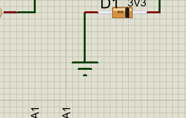
The device is DIODEZENERTEP in TEPZENER.LIB, under Diodes, Zener, with the prefix D and the model TEPZENER.DLL. Search DIODEZENER in Pick Devices. The pins are A on the left and K on the right, on the band side.
The Properties
| Property | What it does |
|---|---|
| Zener voltage, V | the voltage, 3.3 by default |
| Printed voltage while stopped | the value shown on the stopped sheet |
At Run, the model reads the voltage box and sets the print on the glass to the nearest value.
Download Zener Diode Library for Proteus
Click the button below to download Zener-Diode-Library-for-Proteus-v1.0.zip (about 1.7 MB, without the source code of the models):
Zener Diode Library for Proteus V1.0- README.txt: installation, the demo, the properties, troubleshooting and the limits.
- Proteus Library Files:
TEPZENER.LIB,TEPRESISTOR.LIB,TEPLED5MM.LIBand ourArduinoV4TEP.LIB. - Proteus Model Files:
TEPZENER.DLL,TEPRESISTOR.DLL,TEPLED5MM.DLLandTEPARDUINO.DLL. - Arduino Code: the demo sketch.
- Proteus Simulation: the demo project, its HEX file and copies of the DLLs.
No Proteus yet? Read How to Download and Install Proteus 7 and 8. New to libraries? Follow How to Install a New Library in Proteus.
How to Install Zener Diode Library for Proteus
- Close Proteus and extract the whole zip file, for example to your Desktop.
- Copy the files from Proteus Library Files into the LIBRARY folder of Proteus.
- Copy the files from Proteus Model Files into the MODELS folder.
- Delete
TEPZENER.IDXfrom the LIBRARY folder if it is there. - Start Proteus, press P and search for DIODEZENER.
Demo: A Zener Rail Against a Divider
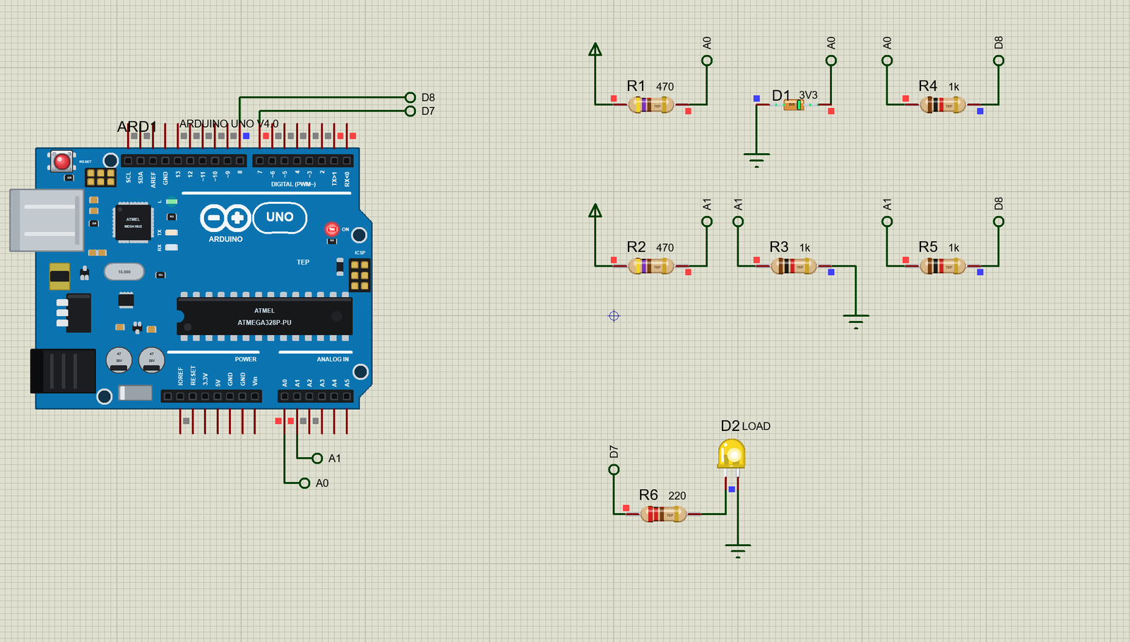
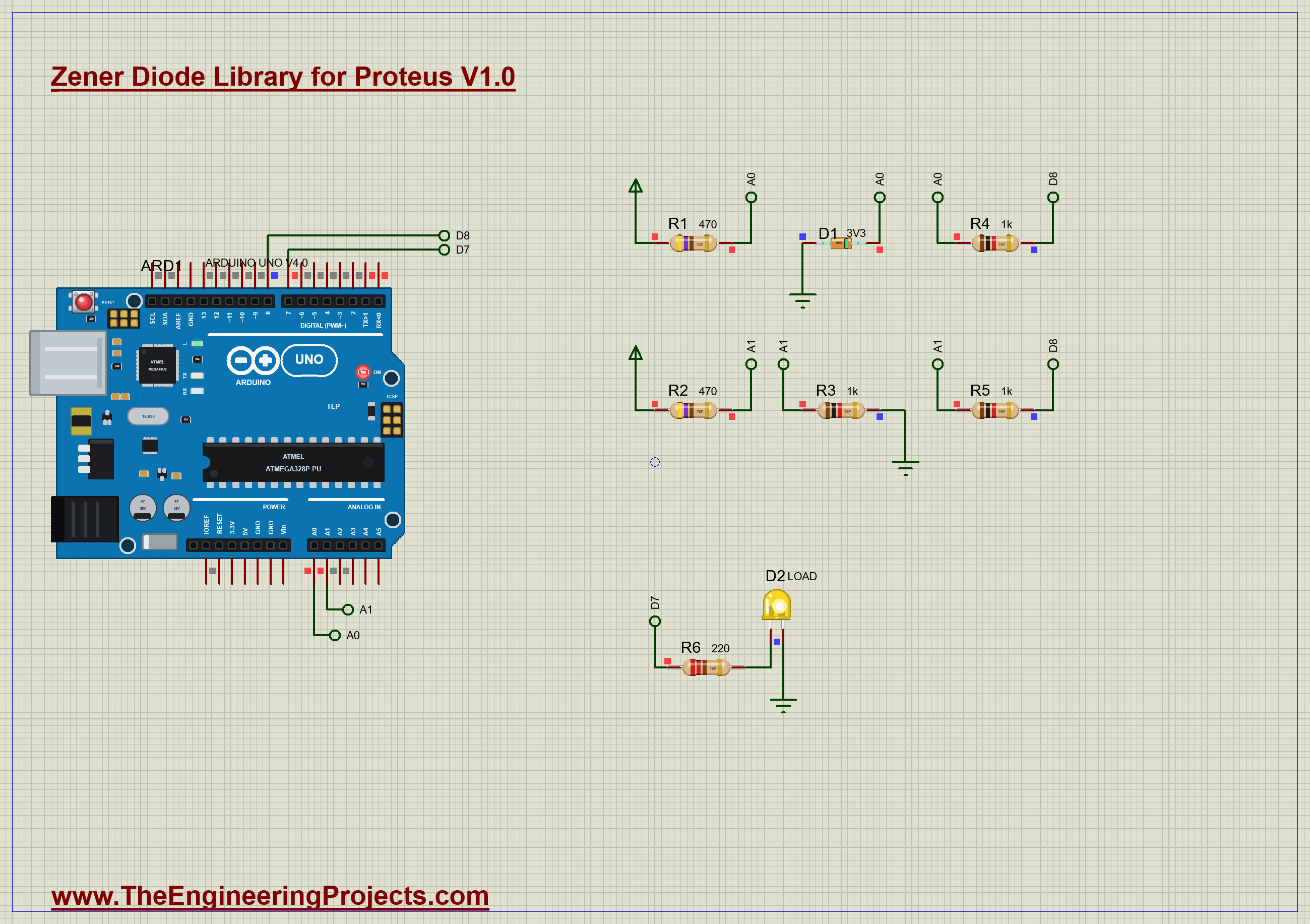
Two resistors in a divider can also give you about 3.3 V from 5 V, and with no special part at all. So why use a Zener? The demo answers that. The top rail on the sheet uses D1, a 3.3 V Zener. The rail below it uses a plain divider. Each has its own 1k load, which the Arduino can switch on through D8, and it reads both rails on A0 and A1. Open Zener-vs-Divider-ArduinoUnoV4.pdsprj. It runs on our Arduino UNO Library for Proteus V4.0, with its built-in monitor, the same window as our TEP Serial Monitor Advance for Proteus. The resistors are from our Resistor Library for Proteus and the LED from our 5 mm LED Library for Proteus.
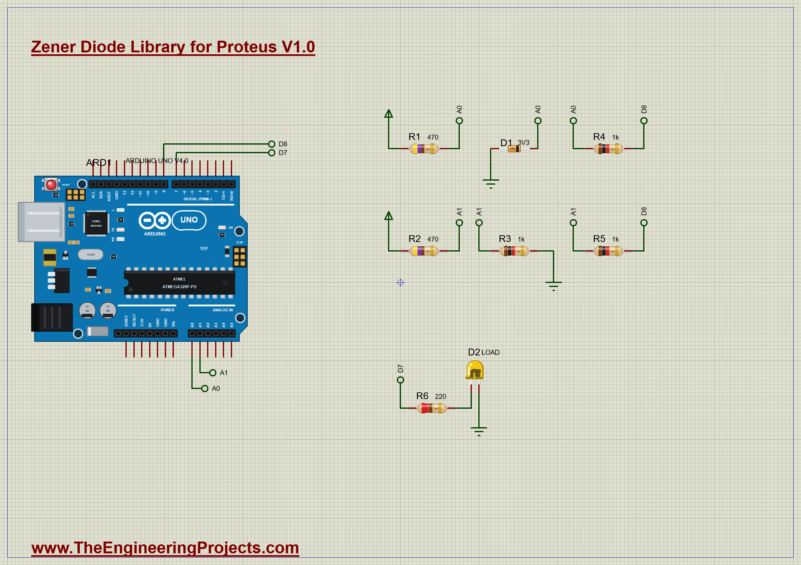
| Part | Connection | Job |
|---|---|---|
| R1, 470 ohm | +5V to A0 | feeds the Zener rail |
| D1, 3.3 V | A0 to GND, band on A0 | holds the rail |
| R2, 470 ohm | +5V to A1 | the top of the divider |
| R3, 1k | A1 to GND | the bottom of the divider |
| R4, R5, 1k | A0 and A1 to D8 | the loads |
| D2 and R6 | D7 to GND | lights while the load is on |
Switching a Load With a Pin
Here is a neat trick. A pin set as an input connects to almost nothing, so the load resistors simply float. Set the same pin as an output and hold it LOW, and it pulls the far end of the resistors to GND. The load is on. So one pin can switch both loads without any transistor:
  if (on) {
    pinMode(LOAD_PIN, OUTPUT);
    digitalWrite(LOAD_PIN, LOW);
  } else {
    pinMode(LOAD_PIN, INPUT);
  }
The Commands
| Type this | What happens |
|---|---|
| load | both 1k loads are switched on |
| free | both loads are taken off |
Run the Demo
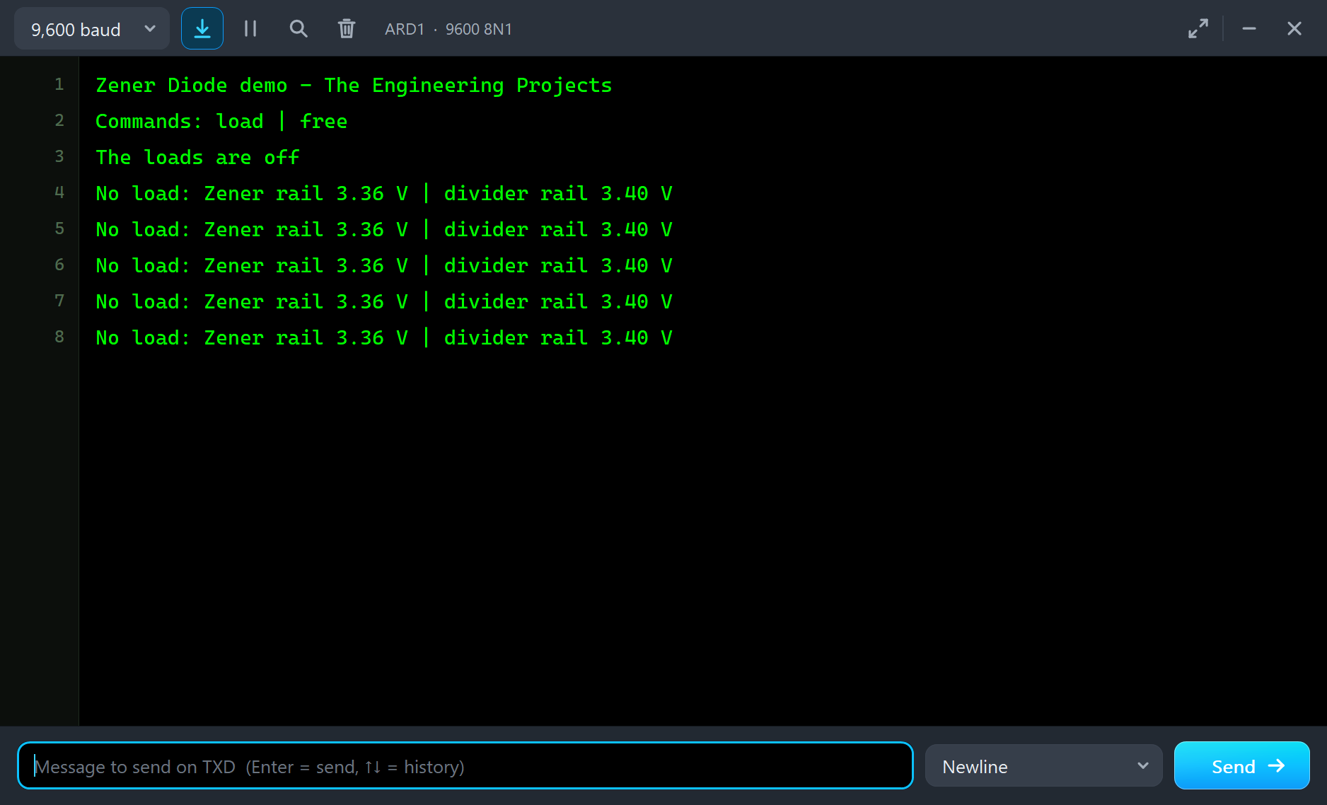
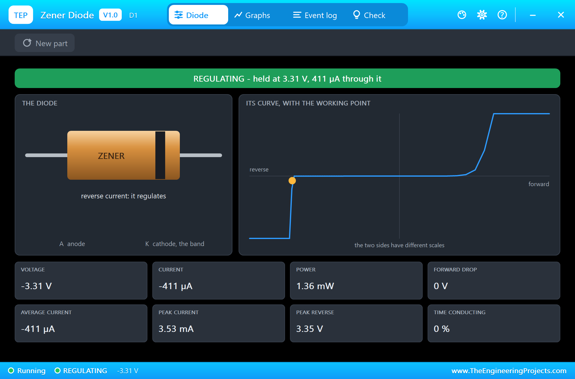
Press Run and the monitor opens. Click the Zener to open its pop-up. The banner says REGULATING, and the amber dot sits on the steep reverse line of the curve:
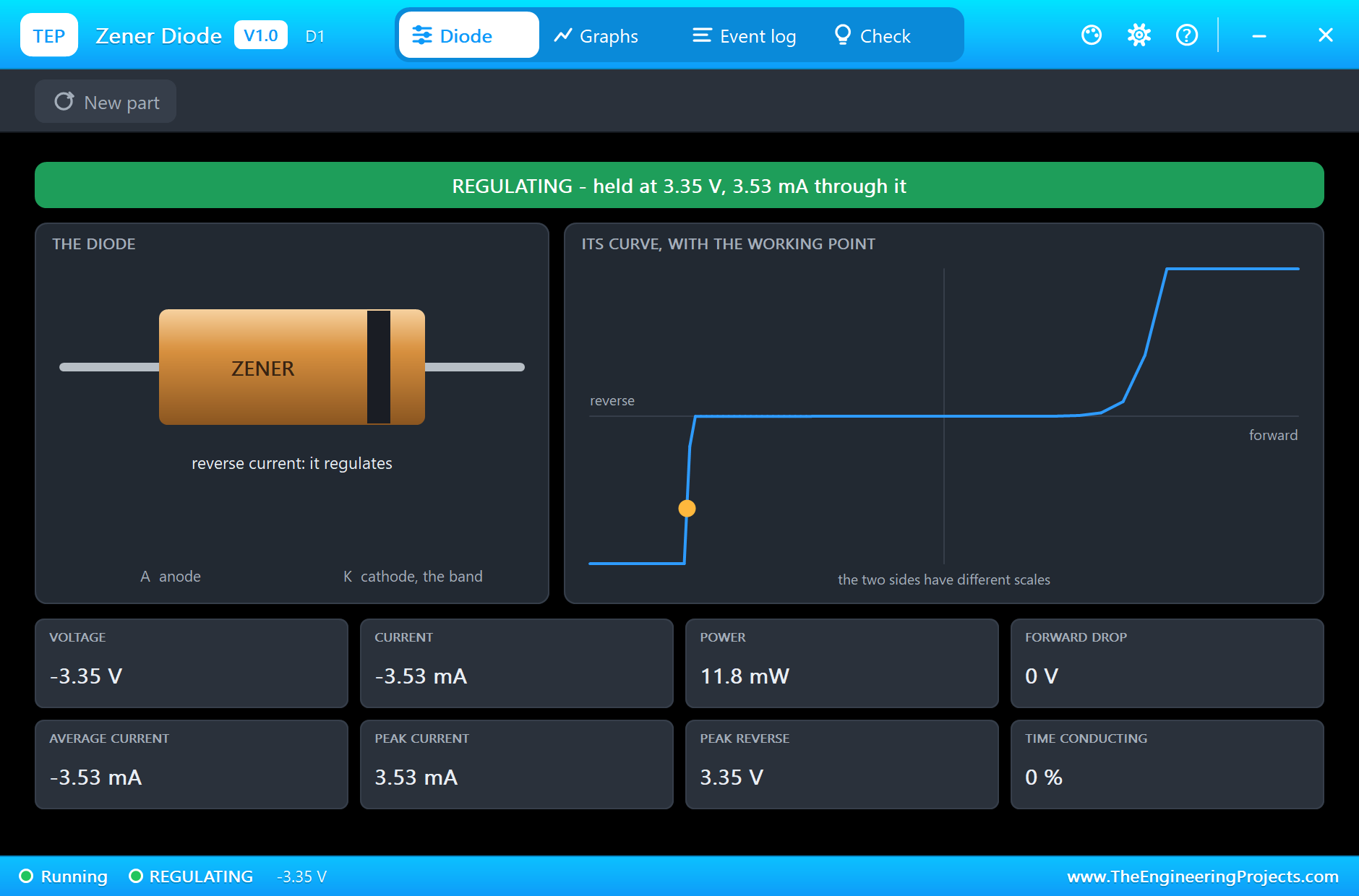
With no load, both rails read very nearly the same. If this were all you tested, you might think that the divider was just as good:
Now Turn the Load On
Type load in the monitor and press Send. D2 lights, and each rail now has 1k on it. Look at the Zener's pop-up: its current has fallen, because the load has taken most of what R1 supplies, but its voltage has hardly moved:
Here is the complete circuit, truly running with the load on:
And here is the verdict in the monitor. The Zener rail stands firm, while the divider falls well away:
| The rail | No load | 1k load | It lost |
|---|---|---|---|
| Zener | 3.36 V | 3.31 V | 0.05 V |
| Divider | 3.40 V | 2.61 V | 0.79 V |
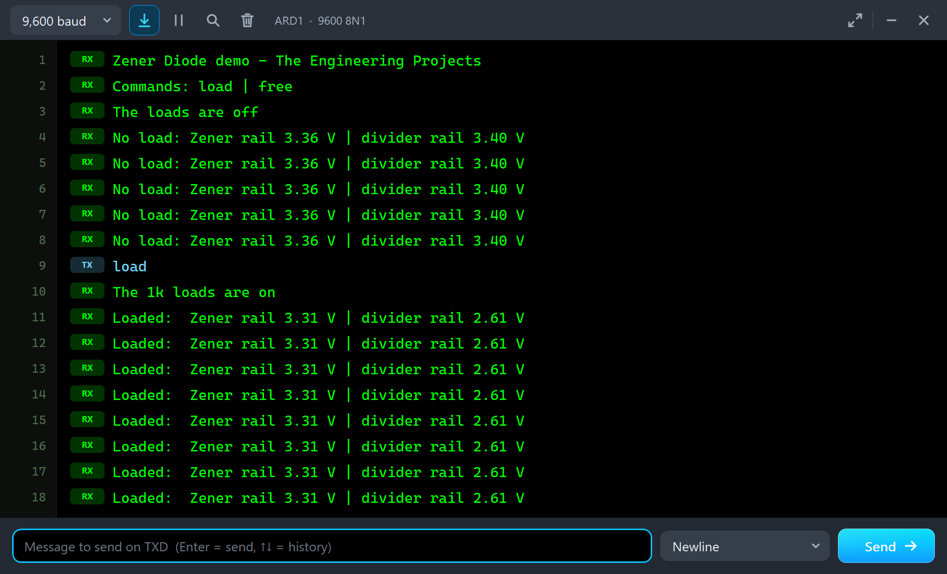
It is easy to see why. The divider's lower resistor now has a 1k in parallel with it, so its bottom half has become 500 ohm. A divider is only as good as the load allows. The Zener does not care about ratios: it simply takes less current, and leaves its voltage where it was.
The Graphs
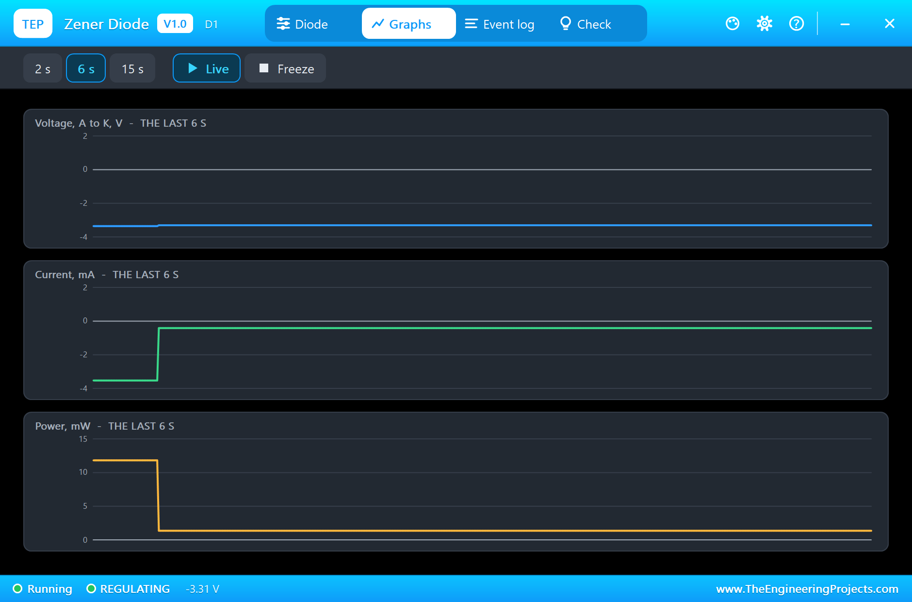
The Graphs tab shows it well. The current through the Zener steps down when the load comes on, but the voltage line stays almost flat:
The Log and the Check Page
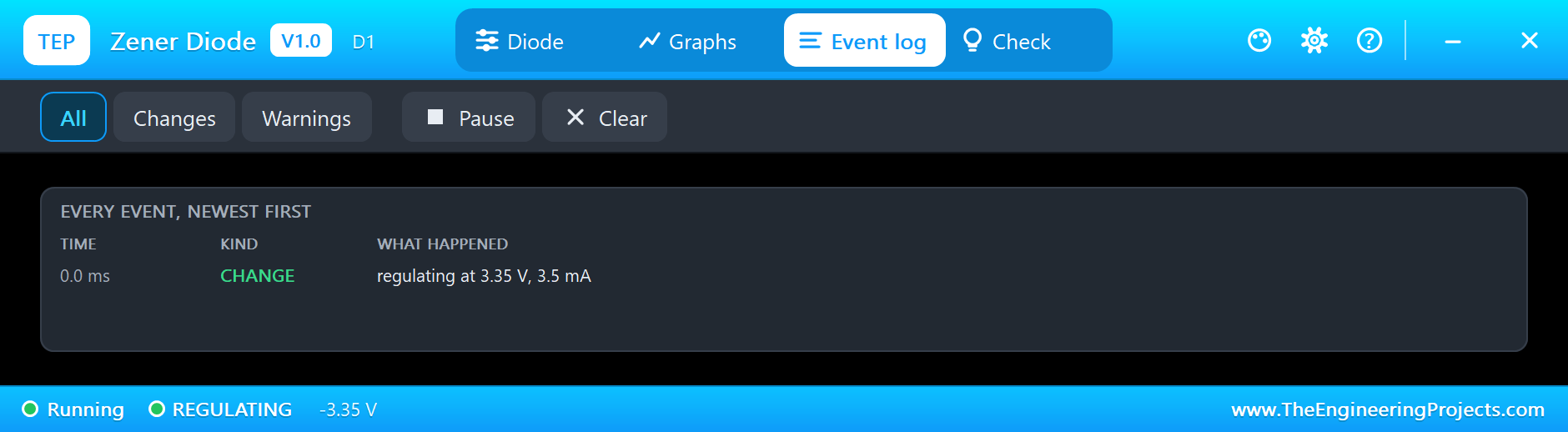
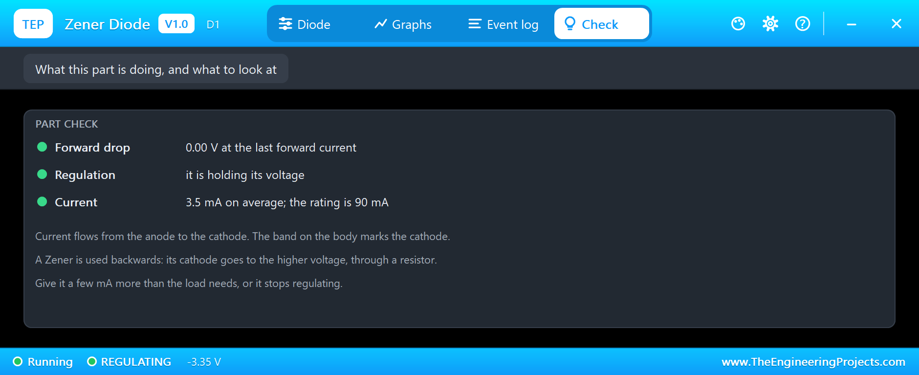
Type free to take the load off. The Event log keeps the record, and the Check page tells you whether the part is regulating:
Try It Yourself
- Change R4 to 470 ohm, and see the Zener run out of current and stop regulating.
- Change R1 to 220 ohm, and see it hold up under the same heavy load.
- Set the voltage box to 4.7, and see the print on the glass change at Run.
- Turn the Zener round, and see it behave like a normal diode at 0.7 V.
- Work out the power in the Zener with no load, and compare it with the pop-up.
Ideas to Extend the Demo
- Protect an analog pin from a sensor that can go over 5 V.
- Add a transistor to make a stronger regulator.
- Use two Zeners back to back to clip a signal both ways.
- Build a simple battery monitor with a Zener as a reference.
Your Own Sketches
The demo sketch is in the zip file, and you can change it in the Arduino IDE. New to Arduino? Start with our Arduino Tutorial for Beginners. Export the compiled binary, and set the UNO's PROGRAM property to the new file. Our guide on How to get the HEX file from Arduino shows you where the file ends up.
Things to Know Before Using a Real Zener
- Always use a series resistor: with no resistor, a Zener across a supply burns out at once.
- Keep some current flowing: a few mA is needed to reach the sharp part of the knee.
- Check the power: the worst case is usually no load at all.
- Expect a tolerance: 5 % is normal, so a 3.3 V part may be 3.1 V to 3.5 V.
- A Zener wastes current: it draws from the supply all the time. For anything serious, a regulator chip is far better.
Troubleshooting
- It does not regulate: the load takes all the current. Use a smaller series resistor.
- It reads 0.7 V: it is the wrong way round. The band goes to the positive side.
- SHORTED: it was overcooked. Fix the circuit first, then press New part.
- The pop-up does not open: click the Zener while the simulation runs.
- The part is not simulated:
TEPZENER.DLLis missing from MODELS and from the project folder.
Limitations of the Simulation
- The soft knee of a real Zener at very low current is simplified to a sharp corner.
- The voltage does not change with temperature, and the noise of a real Zener is left out.
- The tolerance is not modelled: the part is exactly its voltage.
- Arduino is a name of Arduino; this library is not made or endorsed by Arduino or Labcenter.
- Tested in Proteus 8.5 in October 2026 (the demo as shipped). Proteus 7 is not supported.
So, that was all about the Zener Diode Library for Proteus. I hope the two rails show you why a divider is not a regulator, and why this tiny glass bead has lasted so long. If you have any questions, ask in the comments and I will help you out. Till the next tutorial, take care and have fun!